Omron PROFINET: CJ1W-PNT21 and NX-PNC202 Guide
Choose the correct Omron PROFINET role, configure CJ1W-PNT21 controllers or NX-PNC202 remote I/O, map cyclic data and diagnose name, GSDML and module faults.
Review status: Editorially reviewed against current Omron CJ1W-PNT21 and NX-PNC202 product documentation, Omron operation manuals, current Sysmac Studio support information, PI guidance and NIST OT security guidance; exact CPU, unit, firmware, GSDML, tool version, device, topology, electrical design and safety behavior remain project-specific
Direct answer
Omron PROFINET support is role- and hardware-specific. Use the CJ1W-PNT21 when a supported Omron CJ- or documented NJ-series configuration must act as a PROFINET IO Controller. Use the NX-PNC202 when NX-series I/O must form a PROFINET IO Device terminal under a third-party controller such as a supported Siemens controller. These units are not interchangeable, and the Ethernet ports built into an Omron CPU do not become PROFINET merely because they use RJ45 connectors.
For a CJ1W-PNT21 controller project, confirm the exact CPU/rack compatibility, create the PLC I/O table, configure the PROFINET network with the supported Omron tooling, import the current device descriptions for every IO Device, assign unique PROFINET device names, map cyclic input/output data and test each device-loss response. For an NX-PNC202 device project, configure the physical NX terminal and its NX Units in a compatible Sysmac Studio version, export or record the resulting I/O layout, import Omron's controlled GSDML into the third-party IO Controller tool, reproduce the module order, assign the NX-PNC202 a unique device name, then verify configured-versus-actual modules and cyclic data before enabling outputs.
Do not begin with a ping test. A link LED or IP response proves only part of the path. PROFINET cyclic exchange also depends on the controller/device role, exact product identity, device name, GSDML, module/slot layout, input/output lengths, update and watchdog settings, controller configuration, field power and application permissions. Diagnose those layers separately.
This page owns the Omron-specific PROFINET selection, configuration and troubleshooting task. Use the PROFINET PLC guide for vendor-neutral frames, RT/IRT, conformance classes, DCP, slots/subslots, GSDML and MRP. Use the Omron PLC programming tutorial for controller families, CX-Programmer, Sysmac Studio and application logic. Use the exact current Omron manuals for the installed articles as the final authority.
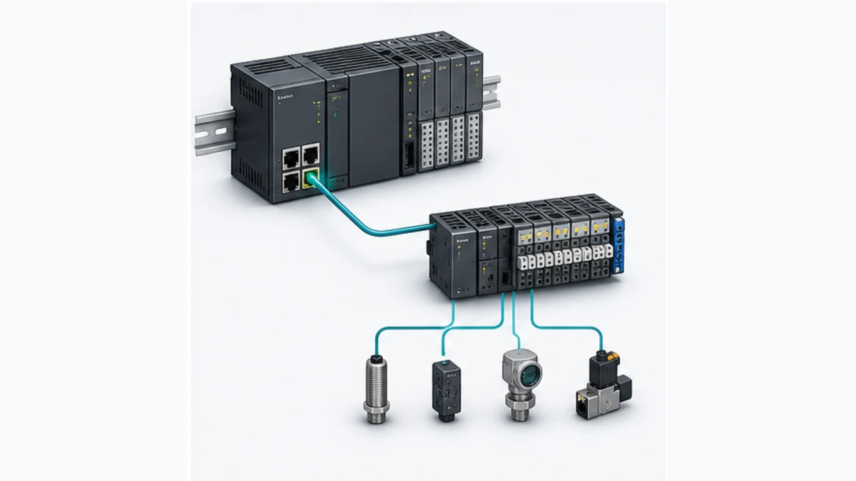
Choose the correct Omron PROFINET owner
| Search or engineering task | Correct owner | Why it stays distinct |
|---|---|---|
| Configure Omron hardware on PROFINET | this guide plus exact Omron manuals | product roles, Omron tools, NX terminal composition and diagnostics |
| Learn generic PROFINET behavior | PROFINET PLC guide | vendor-neutral identity, data model, timing, topology and recovery |
| Program NJ/NX or CJ application logic | Omron PLC tutorial | tasks, variables, ladder/ST, motion and controller-family selection |
| Configure Siemens S7-1200 as controller | S7-1200 PROFINET guide | Siemens controller project, interface and TIA Portal workflow |
| Compare EtherNet/IP and PROFINET | EtherNet/IP vs PROFINET | protocol and ecosystem choice rather than one Omron implementation |
| Design generic remote I/O | PLC remote I/O guide | field power, channel architecture, availability and vendor selection |
The exact keyword has a narrower task than the broad Omron tutorial. A searcher normally has one of two incompatible problems: making an Omron rack control PROFINET IO Devices, or exposing Omron NX I/O as a PROFINET IO Device to another controller. Keeping those roles together on one specialist page prevents a dangerous error—copying controller instructions into a device-terminal project—without duplicating the generic PROFINET reference.
Omron PROFINET hardware roles
CJ1W-PNT21 is an IO Controller unit
Omron describes the CJ1W-PNT21 as a PROFINET IO Controller, commonly called a master in older product descriptions. It is a CJ-series CPU Bus Unit with one PROFINET port. Omron publishes separate operation manuals for CJ-series CPUs and documented NJ-series CPU configurations, so “CJ1W” in the part number does not by itself settle CPU compatibility. Verify the exact CPU, rack, unit version, unit number, support software and manual before ordering or restoring a project.
The controller unit stores and executes the PROFINET network configuration, establishes application relationships with IO Devices and exchanges cyclic data independently of ordinary PLC ladder instructions. The PLC program consumes the mapped words/bits and diagnostic status. A working CPU program cannot compensate for a missing device name, wrong GSDML, mismatched slot layout or controller-unit fault.
NX-PNC202 is an IO Device coupler
Omron's NX-PNC202 forms a PROFINET IO Device terminal consisting of the coupler, selected NX Units and an End Cover. A third-party PROFINET IO Controller configures and exchanges data with that terminal. Sysmac Studio is used to configure and monitor the NX terminal through the supported local connection; the controller vendor's engineering software imports the NX-PNC202 GSDML and owns the PROFINET controller-side project.
This split explains a common misunderstanding. Adding an NX-PNC202 does not add a PROFINET controller port to an NX102, NX1P2 or NJ CPU. It creates a separate remote I/O station that presents its NX Units to an external PROFINET IO Controller. Likewise, an NX-PNC202 GSDML belongs in the controller's catalog; it is not firmware and it does not program an Omron CPU.
Older GRT1-PNT and current alternatives need separate evidence
Omron's current knowledge-base quick start also names the GRT1-PNT as a SmartSlice PROFINET IO Device. Installed-base systems may therefore contain CJ1W-PNT21/CS1W-PNT21 controllers and GRT1-PNT devices even when a new design would use different hardware. Treat lifecycle, availability, software support and replacement as explicit project decisions.
| Product or path | PROFINET role | Engineering owner | Primary boundary |
|---|---|---|---|
| CJ1W-PNT21 on a supported CJ CPU | IO Controller | CX-Programmer I/O table plus supported CX-One/CX-ConfiguratorFDT path | exact CPU, rack, unit and tool versions |
| CJ1W-PNT21 with a documented NJ CPU | IO Controller | Sysmac/CJ unit workflow defined by Omron's NJ-series manual | do not assume every NJ/NX CPU or rack arrangement |
| NX-PNC202 with NX Units | IO Device terminal | Sysmac Studio for NX terminal; third-party controller tool for PROFINET | device role, GSDML and exact NX module support |
| GRT1-PNT SmartSlice terminal | IO Device | supported Omron/third-party tools for that installed family | legacy family and lifecycle-specific evidence |
| Built-in EtherNet/IP port on NJ/NX | EtherNet/IP scanner/adapter capabilities as documented | Sysmac Studio | not PROFINET because the connector is Ethernet |
| Built-in EtherCAT port on NJ/NX | EtherCAT master capabilities as documented | Sysmac Studio | not a PROFINET controller or device |
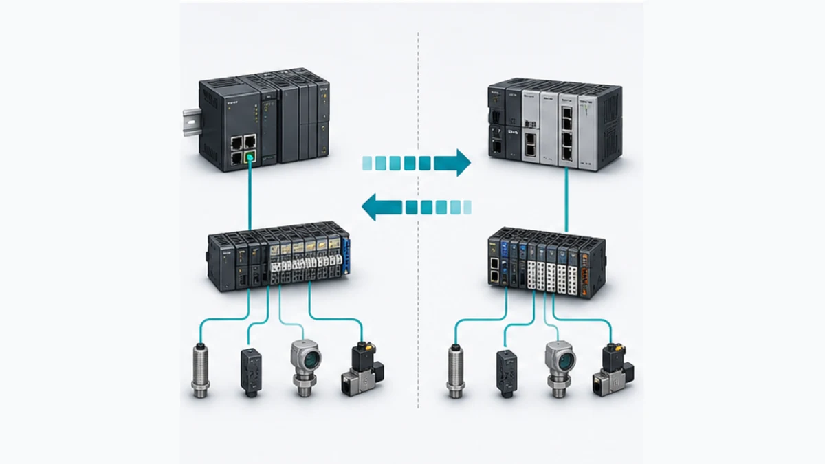
Build a compatibility baseline before configuration
Record exact identity instead of a family nickname
Capture the complete CPU, PROFINET unit/coupler and every remote module order number. Add hardware revision, unit version or firmware, controller project version, support-tool version, GSDML/DTM version, unit number, MAC address, planned device name, IP/subnet, switch port and physical rack position. Photograph labels before wiring ducts or adjacent modules hide them.
For an NX-PNC202 terminal, record every NX Unit in physical order and its terminal-block/power arrangement. For a CJ1W-PNT21 project, record every configured IO Device and the device-description file used to build it. Preserve installer/source checksums where your change-control process allows. A backup without its required DTM/GSDML packages may not be reproducible on the next engineering laptop.
| Evidence | CJ1W-PNT21 controller project | NX-PNC202 device project | Fault prevented |
|---|---|---|---|
| exact article and role | controller unit and supported CPU/rack | device coupler and supported NX Units | controller/device role reversal |
| engineering software | approved CX-One/CX-ConfiguratorFDT or documented NJ path | compatible Sysmac Studio plus controller-vendor tool | unsupported catalog or online functions |
| device description | DTM/GSDML for each connected IO Device | Omron GSDML imported into IO Controller tool | wrong module catalog and data lengths |
| physical order | controller rack/unit number and remote device modules | NX Units left-to-right after coupler | configured/actual slot mismatch |
| identity | controller and each device name/MAC/IP | NX-PNC202 name/MAC/IP | duplicate or blank device name |
| process data | mapped CIO/words/tags and diagnostics | slot/subslot bytes mapped by controller | shifted input/output interpretation |
| lifecycle | product status, spares and restoration media | coupler/NX Unit versions and current manual | replacement that cannot be restored |
Treat current support information as a moving boundary
Omron's Sysmac Studio update information records when support for units such as NX-PNC202 was added and which tool versions support current models. That history matters when opening an old project or commissioning replacement hardware. The newest Sysmac Studio release is not automatically approved for a validated machine, and the oldest project laptop is not automatically capable of the installed unit.
Create a compatibility decision that states the approved software version, why it supports the hardware, which updates are required, how the original project is preserved and which regression tests gate the change. For legacy CJ equipment, also verify operating-system, CX-One update and DTM support before a planned outage.
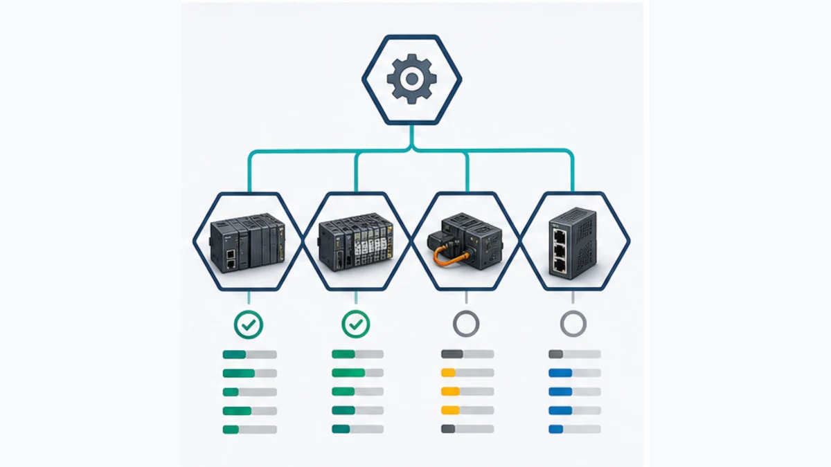
Select CJ1W-PNT21, NX-PNC202 or another network
| Requirement | Prefer | Reason | Hold point |
|---|---|---|---|
| Omron CJ PLC must control third-party PROFINET devices | CJ1W-PNT21 if exact system remains supported | explicit IO Controller role | confirm CPU, rack, device count/data limits and lifecycle |
| Supported NJ configuration needs a PROFINET IO Controller | documented CJ1W-PNT21/NJ architecture | Omron publishes a dedicated NJ-series operation manual | do not extrapolate to an arbitrary NX/NJ controller |
| Siemens or other controller must access Omron NX I/O | NX-PNC202 | explicit PROFINET IO Device coupler | confirm controller compatibility, GSDML and supported NX Units |
| Omron NJ/NX machine needs fast native motion and I/O | EtherCAT path is often the designed fit | integrated deterministic machine-control ecosystem | compare exact timing, redundancy and device requirements |
| Omron controller exchanges standard cyclic data in a CIP ecosystem | supported EtherNet/IP path | common built-in/extension options in Omron portfolio | confirm scanner/adapter roles and connection limits |
| Existing SmartSlice station must remain on PROFINET | GRT1-PNT installed-base path | documented device role | verify lifecycle, spares and migration plan |
| Safety data is required | certified supported safety architecture | ordinary PROFINET does not create a safety function | validate PROFIsafe/CIP Safety/FSoE products and lifecycle separately |
Do not select a gateway merely because it has both protocol names on its datasheet. A gateway creates two independently configured data contracts and new fault states: stale data, quality loss, byte/word order errors, scaled-value mismatch, reconnect timing, write ownership and diagnostic translation. Define those behaviors before purchase and test them under failure, restart and controller-change scenarios.
Live mini-lab
Try it: press START, then STOP
A stop-dominant seal-in rung: START latches the motor output through its own contact, and STOP breaks the circuit.
Watch the output lamp: it stays on after START until you press STOP.
Free to start · runs in your browserOpens plcsimulationsoftware.com — same team
Configure a CJ1W-PNT21 IO Controller
Use a controlled controller workflow
Omron's current quick-start guidance places CX-Programmer and CX-ConfiguratorFDT in the workflow for CJ/CS controllers. The dedicated operation manual is authoritative for unit switches, PLC memory areas, status words, configuration download, device handling and diagnostics. The following sequence is deliberately product-bounded rather than a substitute for that manual.
- Verify the supported CPU, rack, power budget, CJ1W-PNT21 unit version, unit number and engineering versions.
- Back up the PLC and controller-unit configuration, then create or verify the CPU I/O table in the approved PLC tool.
- Build the PROFINET controller network in the supported configurator and import controlled GSDML/DTM packages for the exact IO Devices.
- Add each IO Device with its exact identity, module order, input/output sizes, update/watchdog settings and unique device name.
- Allocate process data and diagnostic/status areas without overlapping PLC memory or silently shifting an existing application map.
- Compile/validate the configuration, download in an approved state and verify controller-unit status before enabling the application.
- Assign names to the intended physical devices using MAC/physical correlation, then prove each configured device enters data exchange.
- Test mapped I/O, device/module diagnostics, controller stop, device loss, link recovery and power-cycle behavior.
The controller network configuration and PLC program are separate but coupled assets. Changing device module order or data length can change what the PLC words mean even when the ladder program compiles. Record the map at the signal level and require a functional checkout after any catalog, DTM, device or network change.
Use the correct manual for NJ-series configurations
Omron publishes a CJ-series PROFINET IO Controller Unit operation manual specifically for NJ-series CPU use. Follow its supported system configuration and Sysmac Studio workflow when that architecture is installed. Do not apply a CX-Programmer screenshot from a CJ2 project to an NJ project, and do not assume the CJ1W-PNT21 can be attached to any NX/NJ product because one NJ family is documented.
Configure an NX-PNC202 IO Device terminal
Build the physical NX terminal first
The terminal consists of the NX-PNC202, supported NX Units and an End Cover. Engineer unit power, I/O power, terminal blocks, field commons, protection, grounding/bonding, conductor identification and environmental limits from the exact manuals. The process-data map cannot correct a missing field supply or an unsuitable terminal block.
Configure the NX Units in a compatible Sysmac Studio version through the supported coupler connection. Make the digital configuration match physical left-to-right order. Set unit parameters, input filtering, analog ranges, channel diagnostics and other supported functions before exporting or recording the terminal structure for the controller project.
Import the GSDML into the third-party controller tool
Omron's NX-PNC202 manual directs the engineer to import the coupler's GSDML into the PROFINET IO Controller configuration software. Obtain it from an official Omron source, preserve its version and checksum, and confirm it contains the exact coupler/unit representations required by the project. Add the NX-PNC202 to the controller network and reproduce the terminal's module/submodule order and process-data lengths.
Give every IO Device a unique PROFINET name. The IO Controller uses the configured name to identify the device and apply the configured IP parameters. Duplicate names, a blank replacement name, a mismatch between project and hardware or selection of the wrong discovered MAC can prevent exchange even when the IP subnet appears correct.
| NX-PNC202 stage | Configuration owner | Acceptance evidence | Common mistake |
|---|---|---|---|
| physical terminal | electrical/NX design | exact coupler, NX Units, terminals and supplies | treating module color as part identity |
| NX Unit parameters | compatible Sysmac Studio | actual-versus-configured unit order and parameters | changing controller catalog only |
| device description | official Omron GSDML | controlled version imported successfully | using a file from an unknown archive |
| controller project | third-party IO Controller tool | matching slots/subslots and byte lengths | reversing input/output from controller viewpoint |
| device identity | controller engineering tool/DCP | unique name assigned to verified MAC | relying on IP or ping alone |
| cyclic exchange | controller plus coupler diagnostics | valid data and quality/status under load | enabling outputs after a green link LED |
| application | PLC tags, interlocks and alarms | each signal and failure state tested | assuming a byte map proves field behavior |
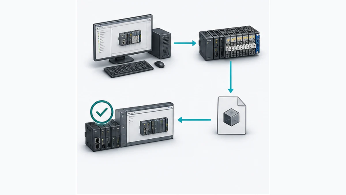
Map cyclic I/O without creating silent offsets
Define the map from the controller viewpoint
In PROFINET, “input” means data produced by the IO Device and consumed by the IO Controller; “output” means data produced by the controller and consumed by the device. Some tools display directions from their local product viewpoint, so record the producer, consumer, byte offset, data type and permitted writer rather than trusting the word input by itself.
The following map is an illustrative review aid, not an NX-PNC202 default. Actual offsets and status bytes come from the configured GSDML modules and controller project.
| Controller byte range | Illustrative content | Producer → consumer | Verification |
|---|---|---|---|
| input 0..1 | 16 digital input bits | NX terminal → controller | actuate one isolated test input at a time |
| input 2..3 | analog input raw word | NX terminal → controller | apply calibrated low/mid/high stimulus and confirm byte order |
| input 4 | device/application status | NX terminal → controller | create the documented negative condition and observe quality |
| output 0..1 | 16 digital output commands | controller → NX terminal | permission/interlock plus terminal measurement |
| output 2..3 | analog output raw word | controller → NX terminal | command bounded points and measure the loop |
| output 4 | command heartbeat or enable | controller → application contract | stop update and prove stale-state behavior |
Do not add a synthetic heartbeat unless the application and device map explicitly support it. Do not overlay status on a process byte for convenience. Use explicit types, documented endianness, bounded scaling and quality handling. For writes, define ownership so an HMI, sequence, maintenance function and network peer cannot fight over the same command.
Connect every byte to a field terminal and behavior
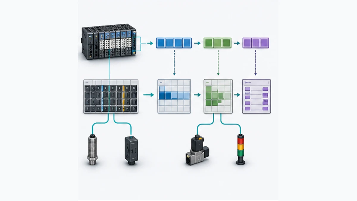
Maintain a cross-reference from PROFINET device/slot/subslot and byte/bit to controller tag, Omron NX Unit/channel or third-party device point, terminal, wire number, instrument, engineering range, normal state, fault state and interlock. This is the map that makes a troubleshooting guide useful at 02:00; a screenshot of the network tree is not enough.
Commission and validate safely
Gate outputs behind electrical and application checks
Follow the site's lockout/tagout, electrical safety, machine-safety, process-isolation and change-control procedures. Before power or download, inspect articles, unit numbers, terminal blocks, power groups, fusing, grounding, network connections and field wiring. Confirm that an output command cannot cause unplanned movement, pressure, heat, chemical release or other hazardous energy.
Never treat a force, disabled task or network disconnect as an isolation method. For safety functions, use the certified product manuals and validation lifecycle. Ordinary PROFINET communication, a standard NX-PNC202 terminal or a browser simulator cannot certify a safety function.
| Acceptance test | Positive evidence | Negative/recovery evidence |
|---|---|---|
| role and identity | correct controller sees intended IO Device at verified MAC/name | adjacent device remains untouched; duplicate/blank name is diagnosed |
| module match | every configured module/submodule matches physical order | wrong or removed test module produces a precise diagnostic |
| digital input | exact field stimulus changes exact tag and sequence state | open circuit/field-power loss follows designed behavior |
| analog input | calibrated points produce correct raw, scaled and quality values | underrange/overrange/wire break follows exact module capability |
| digital output | permitted command drives exact terminal/load | stop, interlock, device loss and power cycle reach designed safe state |
| analog output | bounded commands match measured loop output | communication loss reaches configured substitute behavior |
| controller/device diagnostics | event appears in correct unit and controller records | stale value is not presented as healthy process data |
| recovery | approved link/power interruption recovers within requirement | unexpected auto-restart is prevented where required |
| replacement | approved spare can be named/configured/restored | wrong article, version or GSDML creates a hold point |
Troubleshoot Omron PROFINET by evidence layer
Follow the first-failed-layer rule
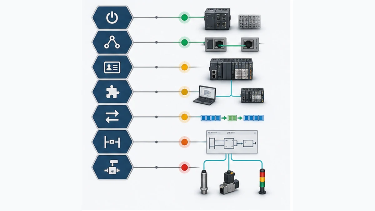
Check power and physical link before identity; identity before controller configuration; configuration before cyclic data; cyclic data before PLC logic; logic before field behavior. Save timestamped evidence at each layer. Random downloads and factory resets destroy the state that would explain the fault.
| Symptom | First evidence | Likely boundary | Avoid first |
|---|---|---|---|
| unit absent and no link | unit/field supply, exact LED pattern, cable and switch port | power, media or wrong port | editing the I/O map |
| device discovered but controller will not connect | project name versus actual name/MAC, GSDML identity | DCP identity or catalog mismatch | guessing a new IP |
| ping succeeds but no cyclic data | controller/device diagnostics and application relationship | name, role, slots, watchdog or data lengths | declaring the network healthy |
| controller reports module difference | configured versus actual order/article | wrong GSDML module or physical NX Unit | shifting PLC offsets manually |
| some channels dead | field supply, terminal measurement and channel diagnosis | wiring, power group or unit parameter | replacing the PROFINET coupler |
| values are shifted or implausible | input/output lengths, offsets, types and byte order | map contract | applying scaling until the value looks right |
| intermittent device loss | timestamps, switch counters, connector/power trace and load | media, EMC, supply, topology or timing | relying on average ping latency |
| replacement stays offline | article/version, factory state, device name and configuration | identity/restoration workflow | renaming multiple devices at once |
| output holds after loss | substitute behavior, stale-state handling and application ownership | risk/control design | treating reconnection as the safety fix |
Read LEDs only with the exact unit manual. Record LED name, color, steady/flashing state, display code and timestamp. Pair that evidence with controller diagnostics, CJ1W-PNT21 status/error areas or NX-PNC202/Sysmac diagnostics, switch counters, a known topology and electrical measurements.
Separate identity, IP and topology
A device name is not an IP address. PROFINET DCP naming/discovery normally operates on the local Layer-2 domain, while ordinary IP tools follow routed rules. A laptop can ping the right IP but assign a name to the wrong MAC; a controller can reject a correctly powered device with the wrong name; duplicate IP or duplicate names can produce different symptoms.
For remote support, do not flatten VLANs or bypass plant security simply to make discovery work. Use the site's approved secure access path, an on-site authorized technician for physical correlation and a rollback plan. NIST's OT guidance emphasizes segmentation, least functionality, controlled remote access, backups and recovery testing because availability and physical consequences differ from ordinary office IT.
Secure, back up and hand over the network
Keep the PLC project, PROFINET controller configuration, Sysmac Studio NX-terminal configuration, GSDML/DTM installers, checksums, software versions, unit/firmware inventory, device-name/IP plan, topology, switch configuration, I/O map, electrical drawings, test results and spare-restoration procedure in the controlled backup. Verify that a clean approved workstation can restore the assets before an outage makes that urgent.
Use unique engineering accounts where supported, restrict tool and controller access, segment the cell according to the risk assessment, disable unused services/ports where documented, control removable media, monitor changes and time-sync diagnostic sources. Do not expose controller, coupler or engineering ports directly to the public internet. Security changes must be tested against cyclic communication, discovery/name assignment, diagnostics and recovery requirements.
Completion means the exact configuration is reproducible, every critical point is mapped and tested, faults are observable, loss/recovery behavior meets the specification and maintainers can restore an approved spare. A green network icon or successful download is only one piece of that evidence.
Use the industrial communication practice lab to rehearse controller/device roles, cyclic maps, stale values and first-failed-layer diagnosis before working on production equipment. The lab is vendor-neutral: it does not emulate CJ1W-PNT21 or NX-PNC202 firmware, Omron engineering tools, GSDML conformance, electrical I/O, network timing, cybersecurity controls or functional safety. Verify those with current Omron documentation and representative hardware.
Frequently asked questions
Does Omron support PROFINET?
Yes, through specific documented products and roles. CJ1W-PNT21 is a PROFINET IO Controller unit for supported CJ and documented NJ configurations. NX-PNC202 is a PROFINET IO Device coupler for an NX remote-I/O terminal. Confirm the exact CPU, unit, firmware and tool combination rather than assuming every Omron Ethernet port supports PROFINET.
Is NX-PNC202 a PROFINET controller or device?
NX-PNC202 is a PROFINET IO Device coupler. It exposes supported NX Units to a third-party PROFINET IO Controller. It does not turn an Omron NX/NJ CPU into a PROFINET IO Controller.
Is CJ1W-PNT21 a PROFINET master?
Yes. Omron describes it as a PROFINET IO Controller, and some product material uses the older master term. Use the dedicated operation manual for the installed CPU family and confirm current lifecycle/support information.
Can I configure NX-PNC202 entirely in Sysmac Studio?
No. Sysmac Studio configures the NX terminal and supported NX Units, while the third-party PROFINET IO Controller engineering tool imports Omron's GSDML and owns the controller-side network, device name and cyclic mapping.
Where do I get the NX-PNC202 GSDML file?
Use Omron's official product/download source referenced by the current NX-PNC202 manual. Preserve the filename, version and checksum. Do not use an anonymous forum attachment for a production project.
Why can I ping the Omron device but PROFINET is offline?
Ping proves IP reachability, not a valid PROFINET application relationship. Check the controller/device roles, configured and actual device name, MAC identity, GSDML, module order, data lengths, update/watchdog settings and controller diagnostics.
Can an NX102 or NX1P2 built-in Ethernet port run PROFINET?
Do not infer that from the connector. Omron documents built-in protocols and roles for each CPU. Use a documented PROFINET product/architecture such as NX-PNC202 for an IO Device terminal or a supported controller solution when a PROFINET role is required.
What is the difference between NX-PNC202 and NX-EIC202?
NX-PNC202 is a PROFINET coupler; NX-EIC202 is an EtherNet/IP coupler. They create remote NX terminals for different industrial Ethernet protocols and use different controller-side descriptions and configuration contracts.
How should I troubleshoot an Omron PROFINET module mismatch?
Compare the exact configured GSDML module/submodule order and data lengths with the physical coupler and every I/O unit. Check unit versions and tool support. Do not hide the mismatch by manually shifting PLC addresses.
Can a browser simulator validate an Omron PROFINET installation?
No. It can teach roles, mappings, stale-state handling and diagnostic reasoning. Only approved engineering software, current Omron documentation, representative hardware, electrical tests and the site's safety/cybersecurity procedures can validate an installation.
Official sources and review boundary
- Omron Europe: CJ1W-PNT21 product page and current downloads
- Omron: CJ1W-PNT21 PROFINET IO Controller Unit Operation Manual
- Omron: CJ-series PROFINET IO Controller Unit manual for NJ-series CPUs
- Omron: NX-series NX-PNC202 PROFINET Coupler Unit User's Manual
- Omron: current Sysmac Studio specifications and supported models
- Omron: Sysmac Studio update information
- Omron Knowledge Base: PROFINET quick start guide
- Omron: CX-One specifications and CX-ConfiguratorFDT
- PI: PROFINET technology overview
- PI: PROFINET device description and GSD fundamentals
- PI: PROFINET cabling and physical-layer guidance
- PI: PROFINET conformance classes
- NIST SP 800-82 Rev. 3: Guide to Operational Technology Security
- CISA: Industrial Control Systems recommended practices
Product pages, manuals, firmware, GSDML, software support and lifecycle status change. Review the current sources for the exact product and market before design or maintenance. This guide does not replace Omron manuals, PI specifications, an electrical design, a machine risk assessment, a cybersecurity assessment or a validated commissioning procedure.
Related reading
Now run it · free to start
Follow plant data from sensor to SCADA
Fieldbus versus Ethernet, Modbus, EtherNet/IP, PROFINET, OPC UA and MQTT, then SCADA layers and alarms, taught on simulated equipment. Free to start.
Ownership disclosure: PLC Programming IO and PLC Simulation Software are operated by the same publisher.
PLC Programming IO Editorial Team
Industrial automation education, references, and software testing
The PLC Programming IO Editorial Team publishes sourced industrial-automation education and documents how material is reviewed, tested, and corrected. A team byline means the publisher is responsible for the page; it does not represent a fictional person or imply an engineering licence.
Coverage:
- • PLC programming concepts and examples
- • Vendor software tutorials and comparisons
- • SCADA, HMI, protocols, and instrumentation
- • Training, careers, and reference material
Review standard:
- • Prefer primary and official sources
- • Record software versions when material
- • Separate tested facts from estimates
- • Publish material corrections
Important scope note
This site provides education, not project-specific engineering approval. Safety, code, and compliance decisions require a qualified person with access to the actual machine and jurisdiction.