PLC Remote I/O Modules: Design and Commissioning
Design and commission distributed PLC I/O with correct adapter ownership, module compatibility, power groups, cyclic timing, fallback states, diagnostics and replacement evidence.
Review status: Editorially reviewed against cited Siemens, Rockwell Automation, Schneider Electric, Beckhoff, ODVA, PI, NIST and OSHA material; exact compatibility, topology, power, timing, fail-state, hot-swap and safety behavior requires installed-product verification
Direct answer
PLC remote I/O is a distributed station that places input and output modules near field devices while exchanging cyclic process data with an owner controller over an industrial network. A typical station consists of a network adapter or bus coupler, a local backplane/expansion bus, compatible I/O modules and terminal/base units, electronics power, one or more field-power or potential groups, and the sensors and actuators. The PLC reads remote inputs and writes remote outputs as part of its process image, but network, adapter and module conversion times sit between the physical signal and the control task.
Design remote I/O by fixing the exact controller, protocol, adapter, firmware, engineering-tool/device-description version, module identities/order, backplane and station limits, power groups, channel electrical types, update rates, connection ownership, network topology, diagnostics, fieldbus-loss output behavior, safety architecture and replacement policy. “24 V remote I/O” is not a compatibility specification: two modules can share voltage and physical appearance while differing in base unit, current, commons, signal logic, isolation, process-data layout or controller support.
Commission in evidence layers. Verify the de-energized as-built station and power segmentation; identify the adapter online; compare expected and detected modules; prove electronics and field power independently; establish controller ownership and cyclic data; actuate one channel at a time from terminal to raw module value to PLC tag; test scaling and diagnostics; interrupt network and power deliberately; verify output fallback and reconnection; then retain a configuration/export, module order, firmware, address, drawings and baseline diagnostic counters. A green network LED does not prove that field power, module configuration, channel wiring or process data is healthy.
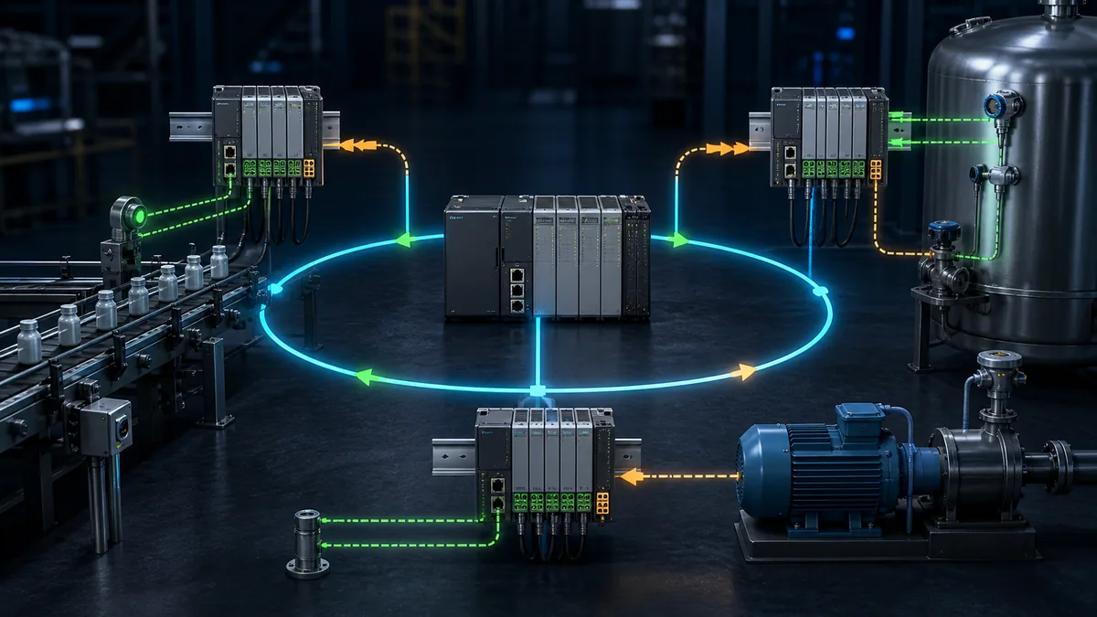
Understand the remote I/O signal path
A local PLC module sits in or directly beside the controller rack. A remote station places the modules behind an adapter on PROFINET, EtherNet/IP, EtherCAT, Modbus TCP, CANopen or another supported network. The application may present both as named tags, yet their timing, ownership, diagnostic and loss behavior can differ.
Identify every layer
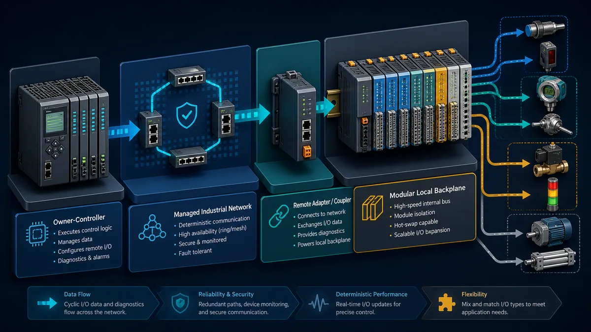
| Layer | Responsibility | Typical evidence | Misleading shortcut |
|---|---|---|---|
| field device/circuit | convert process condition to electrical signal or drive load | terminal measurement, device status and loop documentation | “PLC tag is wrong, so the sensor is bad” |
| terminal/base unit | land conductors, distribute commons/potentials and mechanically key modules | exact base/terminal catalogue number and wiring diagram | assuming every slot base is electrically identical |
| I/O channel/module | condition, convert, diagnose and exchange channel data | raw channel value, module state and channel diagnostics | relying only on front LED |
| local backplane/expansion bus | power module electronics and carry configuration/process data | station/module order and bus diagnostic | treating fieldbus link as proof the local bus is healthy |
| adapter/coupler | terminate fieldbus, own local bus and translate cyclic/acyclic data | identity, state, connection, configuration and bus diagnostics | ping equals configured I/O |
| industrial network | transport cyclic I/O and diagnostics with protocol timing/topology | controller connection, port/counter and protocol state | office-Ethernet assumptions for real-time I/O |
| owner controller | configure/own connections, map process data and execute control | module tree, ownership, task and fault status | tag presence equals current valid data |
| application/HMI | qualify signals, execute logic, alarm and command recovery | quality/freshness logic and diagnostic model | stale last-good value shown as live |
The term adapter is common in EtherNet/IP, device/interface module in PROFINET and coupler in many modular I/O systems. Protocol roles and product names vary, but the architecture remains: the controller-side originator owns or exchanges data with a remote network interface, which manages a local module bus.
Know when remote I/O is a good fit
| Condition | Remote I/O benefit | Design cost introduced |
|---|---|---|
| field devices are far from main panel | shorter multi-core field runs and modular installation | distributed enclosures, power supplies and network infrastructure |
| machine is modular | station can align with machine section and reusable software | identity, module order and reconnect/startup management |
| many analog/specialty channels | local conditioning and channel diagnostics | firmware/configuration and environmental suitability |
| shutdown boundary is localized | potential groups can isolate field loads while diagnostics remain alive | segmentation must be designed and documented correctly |
| expansion is expected | spare station/module capacity and network path | current/backplane/node/connection and address budget |
| high availability is required | supported media/adapter/I/O/controller redundancy can help | validated switchover, topology and replacement complexity |
| deterministic fast control | protocol and module options may meet update needs | full latency/jitter budget; remote is not automatically as fast as local |
Do not distribute I/O merely to save copper when the field enclosure cannot meet temperature, vibration, ingress, hazardous-area, service-access or cybersecurity requirements. A reliable remote station needs suitable environmental protection, power quality, bonding and maintainability.
Select a compatible adapter and module family
Compatibility is a chain: engineering software and controller firmware must support the adapter/device description; the adapter must support the selected local modules and firmware; bases/terminal units must match modules; and the network topology/connection features must match the application.
Build an exact station bill of materials
| Station field | Record | Acceptance question |
|---|---|---|
| adapter identity | full catalogue, series, hardware/firmware and protocol | is it supported by this controller/tool and required network features? |
| device description | GSD/GSDML/GSDX, EDS/AOP/profile, ESI or vendor package version/source | does the project use the controlled manufacturer file for this revision? |
| slot/module order | catalogue, series/revision, channel type and configured slot | does detected order/identity exactly match the approved project? |
| base/terminal unit | electrical/physical variant under each module | does it start/pass power group and provide required terminals/keys? |
| station limits | maximum modules, bytes/connections, bus current and physical length | is planned expansion included in every limit? |
| module load | backplane/electronics current plus field load per group | are adapter and supplies within worst-case derated capacity? |
| environment | enclosure, temperature/altitude/vibration, coating and approvals | does every component meet the installed environment? |
| protocol features | update mode, synchronization, redundancy, fast startup and diagnostics | are controller, adapter, switch and module combinations supported? |
| replacement/keying | compatible/replacement policy and firmware procedure | will a wrong or partially compatible module be rejected visibly? |
| lifecycle/spares | support status, approved spare, configuration and test interval | can the station be recovered without improvisation? |
Rockwell FLEX 5000 documentation describes an owner-controller that checks the configured slot and module; incompatible configuration can be rejected, including through electronic keying. Keying reduces substitution mistakes, but selecting a permissive compatibility mode without understanding what changes can allow a module revision with different behavior. Record the keying policy and test the approved spare.
Siemens distributes controlled device-description files for ET 200SP when configuring outside or across engineering environments, with tool-version compatibility notes. Use the manufacturer's download and change history. Do not install a similarly named GSD or EDS from an uncontrolled archive.
Choose channel type from the field circuit
| Module/channel decision | Questions to answer | Evidence at commissioning |
|---|---|---|
| digital input | DC/AC, sink/source logic, input current/type, threshold, filter, channel/common grouping | raw bit transitions at correct field voltage and intended fault state |
| digital output | transistor/relay/triac, source/sink, load current/inrush, leakage, protection and diagnostics | protected load test plus short/open diagnostic where supported |
| analog input | voltage/current/RTD/thermocouple, isolation, ranges, resolution, conversion/filter and burnout | traceable low/mid/high and fault-condition points |
| analog output | voltage/current, load compliance, isolation and safe/fallback value | measured output at commanded points and on loss/startup |
| temperature | sensor type, wiring (2/3/4-wire), cold-junction/lead compensation and channel isolation | reference simulator points and sensor-break behavior |
| counter/encoder | voltage/driver, frequency, direction, gate/latch and timestamp capability | known pulse rate/direction and rollover/reset test |
| safety I/O | approved safety controller/protocol/module combination and safety parameters | formal safety validation, not ordinary channel checkout |
| IO-Link/specialty | port class, power, device description, cyclic/acyclic data and replacement | device identity, process data and diagnostic event mapping |
Design electronics power and field potential groups
Remote stations commonly separate the supply for adapter/module electronics from the field/load supply passed through terminal/base-unit power contacts. This separation lets network and diagnostics remain active while a field group is off, but only when the selected product and wiring implement it.
Map every power domain
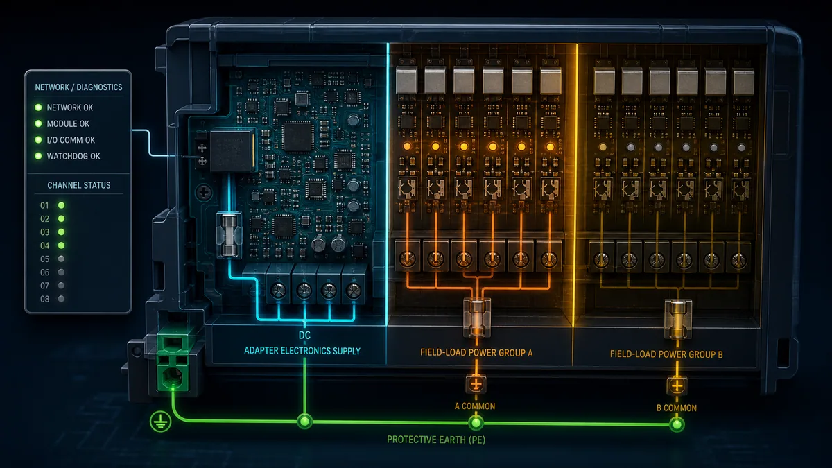
| Power domain | Feeds | Loss behavior to predict | Diagnostic to expose |
|---|---|---|---|
| adapter/interface supply | network interface and often local bus controller | adapter offline or local bus unavailable | adapter power/state and connection loss |
| backplane/electronics bus | module electronics and internal communication | one or more modules unavailable despite field voltage | module/bus state and calculated load |
| input sensor supply | proxes, transmitters or contacts in group | inputs OFF, underrange/bad or last value depending module/application | group supply monitor and channel quality |
| output load supply | solenoids, relays, lamps or actuator electronics | output command may remain TRUE internally while load is de-energized | field-power status plus commanded/feedback state |
| analog/isolated supply | loop/interface circuits | values underrange, open circuit or bad quality | loop/channel diagnostics and supply status |
| safety field power | safety sensors/actuators according to validated design | safety function transitions to designed state | safety-controller/module diagnostics |
| protective bonding/shield | fault-current and EMC paths | unsafe touch potential, noise or communication faults | installation inspection/test under approved method |
Siemens ET 200SP uses specific base-unit types to start a new potential group or continue the group to the right; its system manual states that different potentials on power/AUX busbars require separation with the appropriate base unit. Beckhoff documentation similarly distinguishes coupler/electronics supply from peripheral power contacts. These product examples show why module order and base-unit identity are electrical design data, not only mechanical arrangement.
Calculate group current and protection
For each potential group, sum worst-case sensor and output loads, simultaneous duty, inrush, leakage and module/power-contact limits; apply ambient and conductor derating; select branch/channel protection and commons under local code and product documentation; and include expansion capacity. A 16-channel output module rated at a stated current per channel may still have a lower total per module/common/group.
Do not connect commons from intentionally isolated groups merely to clear an input problem. Determine whether the channel is sourcing/sinking, isolated or common-referenced, and trace the designed return path. For safety or intrinsically safe/hazardous-area circuits, use the applicable certified system and segregation rules.
Live mini-lab
Try it: press START, then STOP
A stop-dominant seal-in rung: START latches the motor output through its own contact, and STOP breaks the circuit.
Watch the output lamp: it stays on after START until you press STOP.
Free to start · runs in your browserOpens plcsimulationsoftware.com — same team
Configure ownership, addressing and process data
The remote adapter must be discovered/named/addressed by the protocol, configured with the expected modules and connected to the correct controller. The software may create tags automatically, map bytes/words into addresses, or expose structured channel objects. Regardless of representation, retain a mapping document from field terminal to application tag.
Create an I/O ownership and mapping register
| Field | Example form | Purpose |
|---|---|---|
| station ID/location | RIO-03 / conveyor discharge |
joins network device, drawing and physical label |
| adapter identity/address | product/revision, device name/IP/node | prevents commissioning the wrong physical station |
| owner/controller | controller and connection/task | resolves which system writes outputs/configuration |
| slot/channel | module 4, channel 2 | exact local-bus location |
| field terminal/wire | base terminal and cable/core | traceable physical path |
| raw data item | generated tag or byte/bit offset | protocol/process-image representation |
| application tag | CV03_PE_EXIT |
stable semantic owner in PLC code |
| data/quality | value, status bits, timestamp/sequence if available | avoid treating bad/stale data as current |
| update class | RPI/cycle/module filter/task relation | documented timing expectation |
| output fail/start state | off, hold, defined value or product-supported option | predictable loss/startup behavior |
| diagnostic/alarm | module/channel/power/connection conditions | maintenance can localize the fault boundary |
| test case | loop-check and failure-injection IDs | ties mapping to acceptance evidence |
On adapter-based EtherNet/IP I/O, an originator/owner establishes cyclic I/O connections and sends configuration as supported. On PROFINET, controller and device exchange cyclic process data under configured device name/topology and modules/submodules. On EtherCAT, the MainDevice configures the SubDevice chain and PDO mapping. On Modbus-based couplers, a client polls/register-maps the station and may need explicit configuration/ownership state. Do not assume changing protocol changes the field circuit; it changes ownership, data representation, timing and diagnostics.
Prevent two writers from owning one output
Some systems support listen-only or shared-input connections, but outputs generally require one unambiguous owner. Engineering tools, web servers or diagnostic clients may offer force/control functions. Schneider documents bus-coupler operating/ownership states and web access that can monitor or control I/O under supported conditions. Control these maintenance paths with access restrictions, mode indication, audit/change procedure and a rule preventing silent conflict with the PLC.
An HMI should not write a remote output directly because it knows a register. Operator requests belong in PLC application logic, where mode, permissives, interlocks, command acknowledgement and safety are enforced.
Engineer timing and determinism
End-to-end input response is not just the PLC scan. It can include sensor response and input filter, module conversion/update, local-bus scan, network production/transfer, controller I/O update, task scheduling and application execution. Output response adds outbound scheduling, module update and actuator response.
Build a latency budget
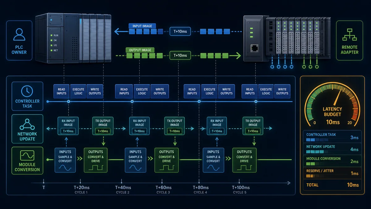
| Timing component | Record | Test method |
|---|---|---|
| field device response | sensor/actuator specification and configured response | controlled physical or signal-simulator transition |
| input filter/debounce | per-channel/module setting | pulse-width sweep and timestamp/trace |
| conversion time | analog/temperature/specialty module mode and channel count | vendor calculation plus measured step response |
| local bus cycle | adapter/module configuration | adapter diagnostic or vendor timing model |
| network update | RPI/update time/cycle, connection and synchronization mode | controller/network diagnostics and packet/time trace |
| controller I/O servicing | producer/consumer update behavior | tag timestamps/sequence and controller documentation |
| application task | period, priority, phase and overrun | controller task monitor and event trace |
| output module update | scheduled/immediate mode and output delay | electrical output measurement under safe test |
| margin/jitter | worst-case network/task/load variation | sustained worst planned traffic and controller load |
Rockwell FLEX 5000 defines a configurable Requested Packet Interval for controller/module exchange and gives a broad product-specific valid range. That range is not a recommendation to set every module to its minimum. Faster RPIs consume controller and network resources; slower RPIs increase age and loss detection. Choose from the process requirement, module conversion, task rate and capacity calculation, then measure.
Do not place a 20 ms analog filter behind a 1 ms packet setting and claim 1 ms process response. Conversely, a fast timestamped input can capture an event more precisely than the controller task that later processes it if the product supports that feature. Document the actual mode.
Define network-loss, power-loss and startup behavior
The most consequential remote-I/O design question is what outputs do when the controller connection, adapter power, field power, local bus or module fails. “Outputs go off” is not universally true and not universally safe. Some loads need de-energization; others need controlled hold, mechanical action or a safety system.
Make fallback explicit per output class
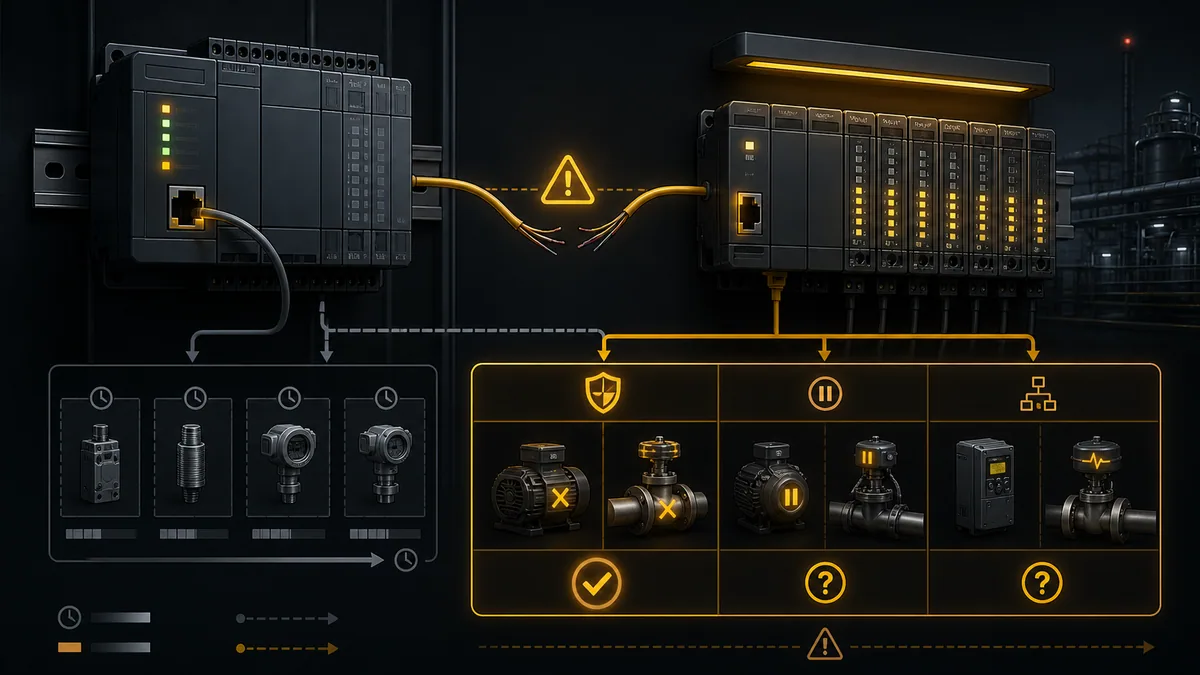
| Event | Inputs/application quality | Output questions | Recovery question |
|---|---|---|---|
| fieldbus connection timeout | last image may remain in memory unless quality logic invalidates it | adapter/module applies off, hold or configured fallback after what timeout? | are commands rewritten before outputs leave fallback? |
| adapter electronics power loss | station unavailable; controller connection faults | outputs lose electronics drive, but relay/mechanical/field circuit behavior varies | does adapter restore and accept owner config automatically? |
| output field-power loss | commanded bit can stay true while load is off | is loss monitored, and can stored/mechanical energy move? | does field power restoration energize an already-true command? |
| input field-power loss | bits may go false or analog bad/underrange | can false be a plausible process state? | require quality/heartbeat before automatic sequence resumes? |
| local expansion-bus fault | station may mark several modules bad or force images/outputs | scope can include downstream/all modules depending system | reset, power cycle or reconfiguration required? |
| module removal/replacement | slot bad/absent; process data invalid | remaining modules and potential contacts may be affected | is hot swap supported and what validation occurs? |
| controller STOP/restart | connection may persist or reconfigure depending platform | program/adapter startup values and outputs before first scan | are permissives and state reconciled before commands? |
| network reconvergence | data path pauses or changes | connection timeout relative to ring recovery | could a brief loss trigger fallback/restart sequence? |
Schneider TM3 documentation states that configured fallback values can be applied on fieldbus timeout, otherwise outputs may be set to zero; it also documents exceptions such as invalid zero ranges/holding last value and describes local expansion-bus error behavior. This is precisely why the tested result must be recorded for the exact firmware, module and channel.
Standard remote I/O is not a substitute for safety I/O. Safety outputs, test pulses, discrepancy timing, PROFIsafe/CIP Safety/FSoE parameters and fault reactions belong to a validated functional-safety lifecycle and exact approved product combination.
Prevent stale input decisions
At the PLC boundary, maintain station/module/channel quality and data age alongside values. If the platform does not provide a timestamp for every item, use connection/module status and an application heartbeat/sequence from the station or device where supported. On loss, block or transition control logic according to the process design rather than allowing the last input image to masquerade as current.
Build a useful diagnostic model
Remote I/O provides richer evidence than “rack fault.” Expose network, adapter, local bus, module, channel, field-power and application states separately. Preserve first fault and timestamps because a single upstream loss can generate many downstream alarms.
Diagnostic hierarchy
| Level | Evidence | Example operator/maintenance message |
|---|---|---|
| controller connection | owned/configured/timeout/inhibited and last change | RIO-03 controller connection lost |
| network path | link/port, topology neighbor, errors/discards and ring state | RIO-03 port 2 link lost; ring recovered |
| adapter identity/state | actual product/revision, address/name, configuration/ownership and local bus | RIO-03 module configuration mismatch |
| station power | adapter, backplane and each monitored potential/field group | RIO-03 field supply group B absent |
| module | slot expected/actual, state, internal/bus fault and keying | RIO-03 slot 5 analog input unavailable |
| channel | wire break, short, over/underrange, diagnostic and raw value | RIO-03 slot 5 channel 2 wire break |
| application consequence | affected process tag/equipment and control response | Tank level unavailable; fill sequence inhibited |
Schneider bus-coupler web diagnostics expose identity, operating/configuration state, Ethernet statistics, I/O protocol messaging and module status on supported products. Siemens and Rockwell engineering diagnostics likewise distinguish device, module and channel conditions. Web interfaces and service ports are also cybersecurity surfaces: restrict access, use supported secure protocols, change defaults, segment networks and monitor changes under the OT security program.
Use a first-out strategy. If adapter electronics power fails, suppress or correlate the expected flood of slot/channel alarms while retaining drill-down. Do not hide a channel wire break behind a generic “remote I/O fault” when the hardware provides the specific evidence.
Commission the station end to end
Commission the station before live process sequences depend on it. Use approved test devices and simulated loads where practical; protect outputs from field faults; and control hazardous energy under site procedure.
Station acceptance matrix
| Gate | Test | Pass evidence |
|---|---|---|
| documentation/identity | compare adapter, modules, bases, firmware, drawings and configuration | exact BOM/order and controlled files match |
| de-energized station | terminal torque/retention per product, conductors, shield/bond, keys and environmental installation | signed visual/electrical inspection under approved methods |
| electronics power | energize adapter/backplane with field groups controlled as designed | expected adapter/local-bus diagnostics and current/load within design |
| field power groups | energize each group independently | correct group boundary; monitored supply and no unintended backfeed |
| network identity | discover/name/address exact adapter and verify physical port/topology | controller reaches intended device with correct identity |
| module configuration | compare expected versus detected slot/module/base and parameters | no keying/config mismatch; diagnostics clear |
| ownership/cyclic data | establish owner connection at planned update | stable input/output sequence and status under controller/task load |
| digital inputs | actuate one field point at a time | terminal, LED/raw channel, generated tag and application tag agree |
| digital outputs | use protected simulated/approved loads before process | command, raw output, terminal/load and feedback agree |
| analog/specialty | apply traceable points/events across range | raw, engineering, quality and conversion time meet specification |
| fault/fallback | interrupt network, power group, module/local bus through approved cases | predicted quality, output state, alarm and recovery each occur |
| performance/security | worst planned traffic/task plus access/configuration checks | latency/jitter/counters and authorized access within acceptance limits |
Use the PLC wiring simulator to rehearse signal paths, commons, input/output states and fault reasoning before connecting field circuits. Use the industrial communication training path for network-layer ownership and cyclic-data diagnosis. Simulation cannot validate the installed station's electrical ratings, network determinism, field power, safety or environmental installation.
Replace or expand remote I/O without creating a second fault
Replacement is a configuration-controlled change, not “same width, same color.” Verify product/series/revision, base/terminal compatibility, firmware, electronic keying, safety signature where applicable, channel type, process-data layout and hot-swap authorization.
Controlled replacement workflow

| Step | Required control | Evidence |
|---|---|---|
| preserve as-found | first fault, LEDs/state, diagnostics, project/config and wiring photographs | failure is not erased before diagnosis |
| establish work state | site hazardous-energy/electrical/process procedure | correct sources and field loads controlled |
| verify spare | exact approved compatibility, firmware and physical/electrical base | part/revision/keying decision recorded |
| protect station | follow supported removal/hot-swap method; prevent power-contact/backplane damage | no assumption that modular means hot-swappable |
| install/reconfigure | correct slot/orientation, module parameters and controlled firmware | expected identity/configuration accepted |
| channel test | repeat affected digital/analog/specialty and diagnostic cases | raw and application behavior matches original design |
| failure test | network/power/fallback and safety validation as change requires | no new restart/fail-state behavior |
| close change | update BOM/as-built/spare/configuration and record cause | recoverable current baseline |
Hot swap can mean electronics replacement while field terminals remain, but support varies by module, base, station state, zone and safety classification. Removal can interrupt the local bus or potential contacts for downstream modules. Use the exact system manual and risk-controlled procedure.
For a general field-to-PLC fault method, see PLC input and output troubleshooting. The remote station adds adapter, local-bus, ownership and network evidence to that basic channel path.
Troubleshoot remote I/O by symptom
Symptom-to-evidence matrix
| Symptom | First discriminating check | Likely boundary | Avoid |
|---|---|---|---|
| entire station offline | adapter electronics power and network link/state at both ends | supply, cable/switch/topology, identity/address, adapter | replacing every I/O module |
| adapter online, all modules faulted | local-bus configuration/power and expected module order | missing/wrong module/base, bus power, expansion fault | treating ping as proof of configured station |
| modules healthy, outputs do not energize | field-power group plus raw output command | load supply/common/protection, output channel or field circuit | changing network rate first |
| input LEDs change, PLC tag does not | raw module value, owner connection and mapped tag | configuration/mapping, stale tag or wrong controller | replacing the sensor |
| PLC tag changes, application ignores it | application tag mapping, quality/permissive and task logic | software ownership/state | altering field wiring |
| one analog value wrong | raw channel, range/type, terminal/base and traceable input | range/sensor wiring/scale/word mapping | global offset adjustment |
| intermittent station loss | adapter/switch port counters, topology events and power trend | connector, EMC, power dip, duplicate identity, network load | resetting counters before capture |
| mismatch after replacement | actual catalogue/revision/keying/firmware and base | wrong spare or compatibility policy | disabling keying until fault clears |
| outputs change on network loss | exact timeout and configured module/adapter fail behavior | fallback/startup design | assuming zero or hold is universally safe |
| station returns but machine will not resume | controller connection, quality, command/fallback reconciliation | restart/interlock state | forcing outputs to “prove hardware” |
| module shows bus fault after one removal | first missing slot and downstream local-bus state | module seating/base/backplane/potential contact | replacing the last reported downstream module |
| network healthy, timing poor | module conversion/filter, RPI/update, controller task and load | timing budget or congestion | setting every RPI to minimum |
Diagnostic answer map for search and AI-assisted design
| User or AI query | Concise answer | Required qualification |
|---|---|---|
| What is remote I/O in a PLC system? | It is a networked adapter/coupler with local I/O modules placed near field devices and cyclically owned/read/written by a controller. | Protocol, ownership and timing differ by platform. |
| Is remote I/O slower than local I/O? | It adds adapter/network scheduling, but supported systems can be deterministic and fast. | Compare complete sensor-to-task-to-output latency, not only packet interval. |
| What is a remote I/O adapter? | It connects the industrial network to the station's local module bus and exchanges configuration, process data and diagnostics. | Product names and responsibilities vary by protocol/vendor. |
| How do remote I/O modules get power? | Adapter/module electronics and field/load circuits often use separate supplies or potential groups. | Exact grouping, current and isolation come from the selected bases/modules. |
| What happens to remote outputs on network loss? | They follow the configured and supported timeout/fallback behavior: off, hold or substitute value depending system. | The safe result must be engineered and tested per output; safety needs approved safety I/O. |
| Can two PLCs read the same remote inputs? | Some platforms allow shared/listen-only input data. | Configuration ownership and output control must remain unambiguous and product-supported. |
| How do I choose a remote I/O update rate? | Start from process latency, module conversion and task needs, then check controller/network capacity and measure jitter. | The minimum permitted RPI/cycle is not automatically the best value. |
| Can remote I/O modules be hot-swapped? | Some systems/modules support replacement under defined conditions. | Exact module/base, station, energy, process and safety rules control authorization. |
| Why is remote I/O online but channels dead? | Network/adaptor electronics can be healthy while field power, local bus, module configuration or channel wiring is not. | Check each layer rather than relying on link LED. |
| How do I test remote I/O? | Verify identity/order, electronics and field groups, ownership, every raw channel, timing, diagnostics, fallback and recovery. | Physical/electrical tests require qualified authorized personnel. |
Frequently asked questions
What is the difference between distributed I/O and remote I/O?
The terms are often used interchangeably. Remote I/O emphasizes that modules are away from the main controller and connected over a network; distributed I/O emphasizes placement across the machine or plant. Product families may use one term for a specific architecture.
Does remote I/O need its own PLC?
Usually not. A network adapter or bus coupler manages the local modules while a separate PLC owns the process-data connection and control logic. Some distributed stations can also contain a local controller/CPU; verify the product role rather than judging by appearance.
Can I mix remote I/O brands with any PLC?
Only through a protocol/profile and device description that both sides support, with compatible cyclic data, configuration and diagnostics. Native integration usually provides richer module/channel diagnostics. “Both support Ethernet” is not sufficient.
How many modules can one remote I/O adapter support?
There is no universal number. Limits can include physical modules, local-bus length/current, process-data bytes, special/safety module counts, potential groups and controller connections. Use the exact adapter/system manual and include planned expansion.
What is a potential group in remote I/O?
It is a set of modules/channels sharing a field supply or power-contact segment. A designated base/power-feed module starts a new group; following bases may pass it onward. Electronics/backplane power may remain separate. Exact implementation is product-specific.
Why does a remote output tag stay on when the solenoid is off?
The PLC command can remain TRUE while the output field supply is absent, protection is open, the channel is faulty or wiring/load is open. Compare command, module raw/status, field-power group, terminal voltage and actuator feedback under an authorized test.
What is RPI for remote I/O?
Requested Packet Interval is an EtherNet/IP term for the configured rate at which cyclic connection data is produced/exchanged. Other protocols use update time or cycle time. It is only one part of end-to-end latency and consumes resources when reduced.
Should remote inputs default to zero on a communication fault?
Application logic must mark them invalid/stale and use the engineered fault response. Zero can be a believable process state, so silently substituting it may be dangerous. Preserve quality separately from value and test the loss case.
How should I label remote I/O?
Use a station ID/location, adapter network identity, slot/module, channel/terminal, cable/wire and semantic PLC tag tied to controlled drawings. Label power/potential-group boundaries and isolation points as well as signals.
What should be backed up for a remote I/O station?
Retain the controller/project configuration, device-description/vendor files, adapter/module identities and firmware, network names/addresses, module order and bases, channel parameters, drawings, safety signature/validation where applicable, test evidence, diagnostic baseline and approved spare/replacement instructions.
Sources, review scope, and limitations
This guide was reviewed on August 28, 2026 against current public system and protocol documentation. Limits and behavior vary by controller, adapter, module, base unit, firmware, device-description file, network and engineering software. Verify the exact installed combination and retain the tested documentation revision.
- ET 200SP Distributed I/O System Manual — Siemens
- ET 200SP HA Distributed I/O System Manual — Siemens
- FLEX 5000 Standard and Safety I/O Modules User Manual — Rockwell Automation
- TM3 I/O configuration, fallback and expansion-bus error handling — Schneider Electric
- TM3 Ethernet bus-coupler web and diagnostics — Schneider Electric
- TM3 Modbus serial bus-coupler register and diagnostics mapping — Schneider Electric
- Bus-coupler electronics and peripheral power supply — Beckhoff
- EtherCAT Hot Connect principle — Beckhoff
- EtherNet/IP technology and resources — ODVA
- PROFINET technology and system description — PROFIBUS & PROFINET International
- NIST SP 800-82 Rev. 3, Guide to Operational Technology Security
- 29 CFR 1910.147, control of hazardous energy — OSHA
The images are conceptual and do not define terminal assignments, compatible modules, power segregation, conductor protection, network topology, timing, output fail states or safety functions. This page does not authorize energized measurement, forcing outputs, hot swap, safety-module changes or live process tests. Only qualified, authorized personnel following the site risk assessment, electrical and hazardous-energy procedures, engineered drawings, manufacturer manuals, cybersecurity controls, management of change and functional-safety lifecycle should install, configure, test or replace remote I/O.
Now run it · free to start
Learn a repeatable way to find the fault
Split a stopped machine into input, logic, output and physical response, and take the measurement that proves each stage. Practised on simulated machines. Free to start.
Ownership disclosure: PLC Programming IO and PLC Simulation Software are operated by the same publisher.
PLC Programming IO Editorial Team
Industrial automation education, references, and software testing
The PLC Programming IO Editorial Team publishes sourced industrial-automation education and documents how material is reviewed, tested, and corrected. A team byline means the publisher is responsible for the page; it does not represent a fictional person or imply an engineering licence.
Coverage:
- • PLC programming concepts and examples
- • Vendor software tutorials and comparisons
- • SCADA, HMI, protocols, and instrumentation
- • Training, careers, and reference material
Review standard:
- • Prefer primary and official sources
- • Record software versions when material
- • Separate tested facts from estimates
- • Publish material corrections
Important scope note
This site provides education, not project-specific engineering approval. Safety, code, and compliance decisions require a qualified person with access to the actual machine and jurisdiction.