PROFINET for PLC Systems: Configuration and Troubleshooting
Configure a PROFINET PLC network from GSDML and device names through slots, cyclic I/O, update timing, topology, MRP, diagnostics, replacement and acceptance testing.
Review status: Editorially reviewed against cited PI, Siemens, CODESYS, Beckhoff and NIST documentation; exact features, timing, topology, diagnostics, security and fail behavior require product-, firmware- and project-specific verification
Direct answer
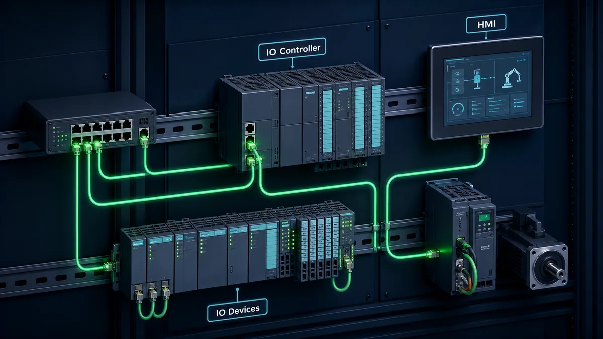
PROFINET connects a PLC acting as an IO Controller to distributed IO Devices such as remote I/O, drives, valve islands and instruments over industrial Ethernet. An engineering station or HMI can act as an IO Supervisor for commissioning and diagnosis. The controller and each device exchange cyclic process data through a configured Application Relation; parameters, identification records and diagnostics also use acyclic services. A working Ethernet link or successful ping does not prove that the PROFINET relationship, expected module structure or process data is valid.
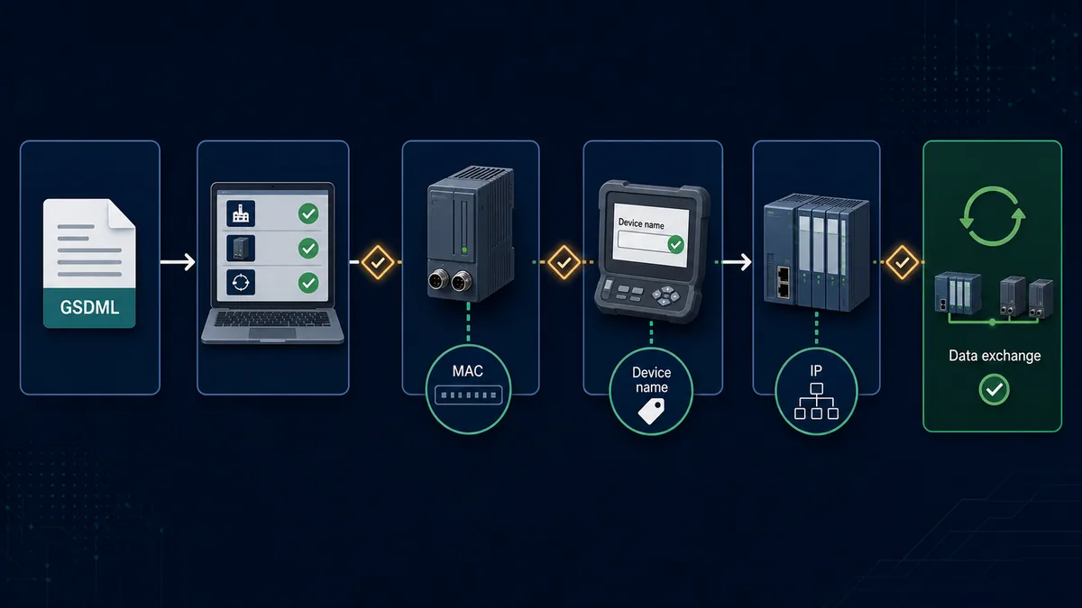
Commission in this order: select the exact device and revision from its vendor GSDML, configure modules and submodules, assign a unique PROFINET station name to the physical device, verify the planned IP and topology, establish cyclic data exchange, map input/output bytes with quality, align update and PLC task timing, then test alarms, link loss, device loss, MRP recovery if used, replacement and restart behavior. Preserve the expected-versus-actual evidence at every gate.
PROFINET device identity is name-centered during onboarding. The engineering tool can discover an unnamed device by MAC address on the local network and assign its configured station name using Discovery and Configuration Protocol services. The controller then checks or supplies the planned IP parameters during startup. An IP address alone is not a substitute for the correct station name, device identity and module/submodule configuration.
Understand PROFINET roles and communication
PI's system model defines three useful roles. The role describes what a node does in the PROFINET system; it is not inferred safely from its shape, IP address or marketing name.
Separate controller, device and supervisor responsibilities
| Role | Typical product | Primary responsibility | Commissioning evidence |
|---|---|---|---|
| IO Controller | PLC, controller CPU or controller runtime | configures devices; consumes input data; provides output data; receives alarms | controller interface healthy, AR established, expected devices and data valid |
| IO Device | remote I/O, drive, coupler, instrument, robot interface | provides inputs; consumes outputs; exposes slots/subslots, records and diagnostics | correct station name, identity, module structure, parameters and cyclic state |
| IO Supervisor | engineering workstation, diagnostic PC or HMI | discovery, naming, configuration, record access and diagnosis as supported | authorized access, correct network interface and controlled project/tool version |
A single physical product can expose more than one communication role, but only if its documentation and configuration support that mode. Do not use the older “master/slave” label as the configuration decision: verify whether the software object and interface are an IO Controller or IO Device.
Distinguish cyclic data from acyclic records and alarms
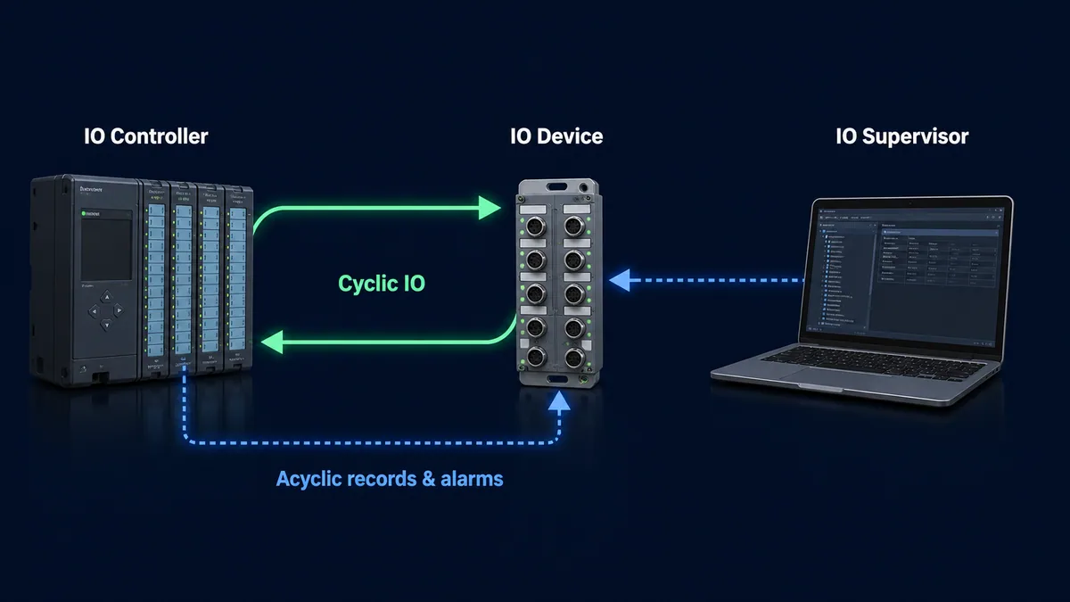
PROFINET cyclic I/O follows a provider-consumer model: controller and device send their configured data independently at the negotiated schedule, with provider and consumer status indicating validity. Acyclic services carry configuration, parameter records, identification/maintenance information and diagnostic data. Devices also issue alarms for changes such as module or channel diagnosis.
| Communication surface | Typical contents | Timing expectation | Failure question |
|---|---|---|---|
| cyclic input data | sensor states, feedback, measured values | configured real-time update | is the value current and provider status GOOD? |
| cyclic output data | commands, setpoints, control words | configured real-time update | which controller owns it and what happens on loss? |
| cyclic status | provider/consumer validity per relationship/submodule | travels with process exchange | did the PLC separate bad quality from a plausible value? |
| acyclic parameter record | mode, range, calibration or device parameter | on startup or controlled request | is record index/subslot/revision correct? |
| identification record | vendor, order/product, serial, version and maintenance fields | commissioning/asset workflow | does actual identity match the approved project? |
| diagnostic alarm/record | device, module, submodule or channel condition | event plus controller retrieval/presentation | what was the first fault and exact source? |
An Application Relation (AR) is established between a controller and device for configuration, process exchange and diagnosis. When the AR is missing, diagnose naming, reachability, identity and configuration. When the AR exists but data is bad, move to submodule status, mapping, ownership, timing and device-specific diagnostics.
Choose the required real-time capability
PROFINET is a family of capabilities rather than one universal cycle specification. PI documentation describes Conformance Classes and application classes; device certification and engineering-tool compatibility determine what a particular product combination can use.
Use RT, IRT and newer capabilities only when the application requires them
| Capability | Practical use | Engineering requirement | Common mistake |
|---|---|---|---|
| PROFINET RT | general factory I/O, drives and controller-device cyclic exchange | supported controller/device/switching, capacity and update-time design | assuming “real time” guarantees a chosen end-to-end response |
| topology/diagnostic functions associated with richer conformance | neighbor discovery and network diagnostics | supported ports/devices, LLDP active and correct topology configuration | drawing topology but never comparing expected and actual neighbors |
| IRT | synchronized/high-performance motion and isochronous applications | compatible certified components, clock/topology planning and vendor engineering | selecting IRT because it sounds faster without a motion requirement |
| TSN-related/newer PROFINET functions | converged deterministic networking in supported ecosystems | exact current controller, device, switch, profile and tool support | assuming ordinary TSN-capable Ethernet makes every device interoperable |
| PROFINET security profiles / newer conformance | authenticated provisioning and protected communication where implemented | products certified for the applicable specification/profile and lifecycle | claiming security from protocol name while using legacy/open services |
As of this guide's review, PI lists PROFINET specification version 2.5 with structural security changes and a security profile, and describes a new CC-E alongside existing classes. That does not mean an installed controller or device supports version 2.5, CC-E or secure provisioning. Check the PI certification record, vendor release documentation, GSDML compatibility and firmware for every node. Do not silently enable a new protocol/security mode on a running plant network.
Convert a process requirement into a network requirement
Start with the physical event and acceptable worst-case reaction. Include sensor/filter time, module conversion, network update, controller I/O servicing, logic task, output update and actuator response. Define tolerated jitter, data age, loss detection and failure action. Only then choose update class and hardware.
| Requirement question | Example decision artifact | Why it matters |
|---|---|---|
| how fast can the process change? | minimum meaningful event/pulse and acceptable reaction | prevents using average scan time as a specification |
| must nodes be synchronized? | motion/measurement phase error and clock requirement | distinguishes ordinary RT from isochronous need |
| how much loss is tolerable? | watchdog threshold and engineered substitute state | links communication timeout to process behavior |
| can one packet/reconvergence be missed? | sequence behavior and controller recovery test | avoids calling a redundant network “zero loss” |
| what diagnostics are required? | device/module/channel and topology acceptance | influences product/conformance/tool selection |
| what security lifecycle is supported? | certified mode, identity, key/certificate and recovery process | prevents security feature from becoming an availability hazard |
Import and control the GSDML device description
GSDML is the machine-readable device description used by an engineering system to present a PROFINET device's identity, Device Access Points, modules, submodules, process-data sizes, parameters, diagnostics and communication capabilities. It is not firmware and does not prove the physical device matches the project.
Match vendor, device, DAP, revision and engineering tool
Obtain the GSDML from the device manufacturer or controlled engineering repository. Preserve its filename/version and the product firmware/revision with the project. Some tools install multiple device descriptions and automatically choose or offer a Device Access Point. Compare the identity fields and supported hardware revision rather than choosing the newest-looking catalog item.
| GSDML gate | Expected evidence | Failure if wrong |
|---|---|---|
| source and integrity | vendor-controlled download/repository, retained original and change record | altered, unofficial or untraceable device definition |
| GSDML schema/tool support | file imports without ignored/unsupported feature warnings | catalog missing or definition partially interpreted |
| vendor/device identity | Vendor ID, Device ID/product family and order code align | controller rejects actual device or shows identity mismatch |
| Device Access Point | DAP represents exact interface/product mode | wrong module tree, limits or process layout |
| hardware/software revision | declared supported ranges cover installed product/firmware | startup or parameterization failure after replacement/update |
| module/submodule list | physical/order configuration is permitted | expected versus actual module difference |
| process data/parameters | byte lengths, directions and records match controlled interface | shifted tags, rejected configuration or unsafe assumptions |
Beckhoff's official troubleshooting guidance specifically calls out correct GSDML, DAP, version and controller/device adapter selection. Treat a GSDML refresh as a controlled change: it may add catalog choices without rewriting existing modules, or it may expose compatibility differences that need review and regression testing.
Keep the project reproducible
Archive the controller project, exact GSDML, vendor manual, firmware package/reference, topology export, name/IP list, module order, parameter report, process-data mapping and acceptance evidence. A backup that opens but cannot recreate the device catalog or firmware baseline is incomplete.
Assign the PROFINET device name and IP correctly
The configured station name links the project device to the physical IO Device. During initial commissioning, a tool discovers nodes—often by MAC address while no name/IP is present—then writes the planned name. The controller uses the name to identify and configure the device, including IP settings as supported by the stack.
Follow the identity workflow in order
| Step | Action | Required proof |
|---|---|---|
| 1 | configure exact device/DAP and modules from controlled GSDML | project identity and process-data footprint approved |
| 2 | connect the engineering station to the intended local PROFINET network | correct physical adapter/VLAN; authorized maintenance window |
| 3 | scan live devices and select the physical node by MAC/product/LED signal feature | label, location and observed product agree—not merely nearest IP |
| 4 | check for duplicate/wrong names before writing | name register has one planned owner and no collision |
| 5 | assign the configured PROFINET station name using supported engineering/DCP workflow | device reads back exact name after power cycle as expected |
| 6 | let controller/tool apply or verify planned IP/subnet parameters | actual IP and controller project agree; no duplicate IP |
| 7 | establish AR and compare expected versus actual identity/modules | cyclic state reached with data status valid |
PI's commissioning guideline notes that name assignment from an engineering tool is performed on the same subnet using the device's MAC address. Network infrastructure can also define DCP boundaries that stop Identify/Hello traffic. If a scan cannot see a device, confirm the selected PC interface, local Layer-2 path, switch/VLAN/boundary configuration and device link before guessing an IP address.
Diagnose name and IP symptoms without factory-reset roulette
| Symptom | First discriminating evidence | Likely cause |
|---|---|---|
| device appears in scan but controller cannot connect | actual station name versus configured name | blank, spelling/case/format mismatch, duplicate or name on wrong unit |
| ping succeeds but device not in data exchange | AR/identity/module diagnostic | IP reachability exists; PROFINET configuration does not match |
| controller repeatedly changes IP | project name/IP ownership and actual station name | controller is applying its configured parameters at startup |
| replacement stays unnamed | supported name-transfer/topology method and factory state | memory card/name transfer absent or topology replacement preconditions unmet |
| two physical units seem to alternate/fault | duplicate station name/IP and MAC list | duplicate identity or unintended network bridge |
| scan sees nothing beyond one switch | DCP boundary/VLAN/selected adapter | discovery traffic is not forwarded over that boundary |
Do not reset a device until its as-found name, MAC, IP, identity, LEDs and controller diagnostics are preserved. A reset can remove the evidence that distinguishes duplicate naming from a failed device.
Live mini-lab
Try it: press START, then STOP
A stop-dominant seal-in rung: START latches the motor output through its own contact, and STOP breaks the circuit.
Watch the output lamp: it stays on after START until you press STOP.
Free to start · runs in your browserOpens plcsimulationsoftware.com — same team
Configure slots, subslots and process data
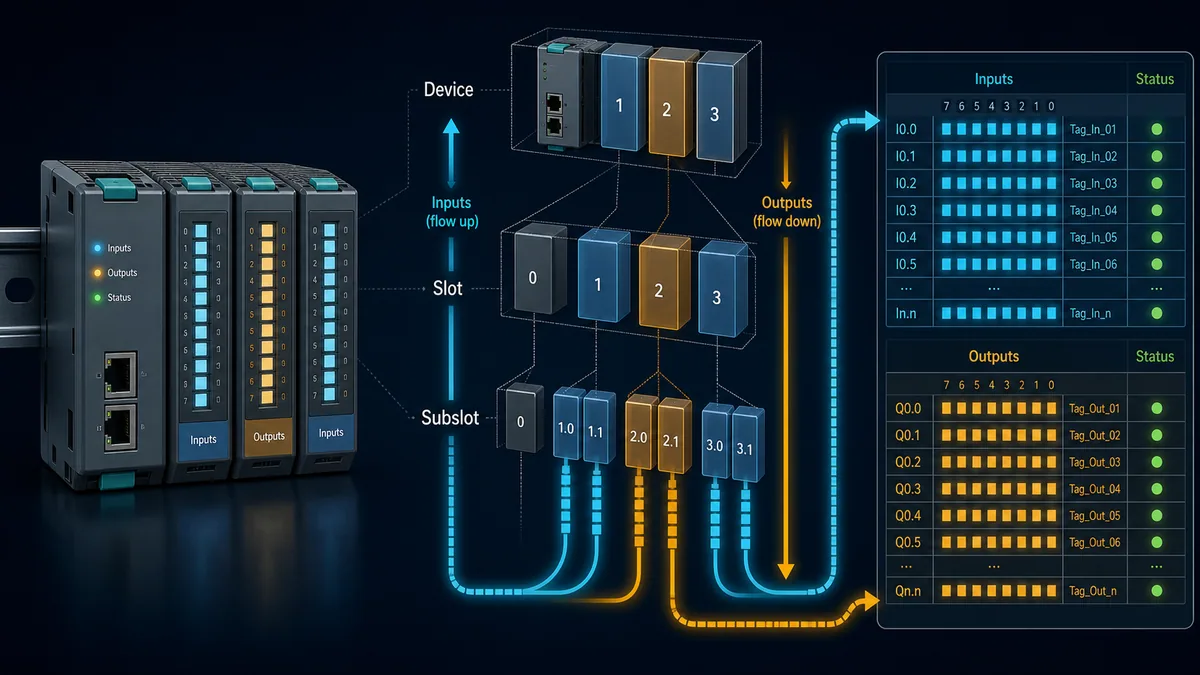
A PROFINET IO Device is modeled as modules in slots and submodules in subslots. Actual process data and many parameters/diagnostics attach to submodules. The interface and physical ports are also represented through defined submodules, which is why topology and port diagnosis can be available through the device model.
Map expected hardware to the PLC image
| Mapping field | Record in the interface contract | Verification |
|---|---|---|
| device/station | stable equipment ID plus PROFINET station name | physical label, live MAC/name and project agree |
| API/slot/subslot | exact protocol location | online expected/actual tree and device documentation |
| module/submodule identity | configured and actual order/revision | no module difference or substitute mismatch |
| direction and byte length | input, output or bidirectional; exact bytes/bits | controller address footprint and GSDML agree |
| raw representation | bit, signed/unsigned integer, float, byte array/control word | distinctive controlled values and vendor interface definition |
| engineering meaning | semantic tag, units, scale/range and state enumeration | compare device display/vendor tool and PLC raw/engineering value |
| status/quality | provider/consumer data validity and device-specific status | force approved communication/module fault and observe invalid handling |
| ownership | controller/task/application responsible for output | no second writer or diagnostic tool control conflict |
| parameter record | index, subslot, value, startup/download policy | upload/readback where supported and controlled restart test |
| lifecycle | GSDML, firmware, project and interface versions | reproducible backup and change review |
Do not map only the numerical value. CODESYS exposes device states including running, communication error, diagnosis, module difference and aggregate data validity. Other platforms expose similar evidence with different names. Application logic should carry quality/data age separately enough that a last good value cannot silently masquerade as current data.
Separate commands from status
For drives and intelligent devices, distinguish PLC-to-device control words/setpoints from device-to-PLC status words/actual values. Implement the vendor profile or documented telegram exactly. A bit numbered 0 in a status word is not automatically the same meaning as bit 0 in a control word. Preserve handshakes, sequence numbers or acknowledgements defined by the profile.
Ordinary PROFINET output ownership belongs to one controller relationship. An HMI request should enter PLC application logic, where modes, permissions, interlocks and acknowledgements are enforced, rather than writing field outputs through an unrelated maintenance interface.
Engineer update time, watchdog and PLC task timing
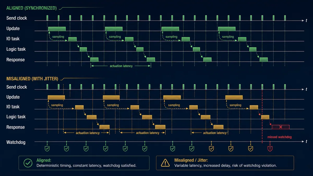
The configured send clock and reduction ratio determine a cyclic send interval in stacks that expose those parameters. For example, official CODESYS documentation defines send cycle as send clock multiplied by reduction ratio and defines monitoring time as a multiple of that cycle. Valid choices remain product- and configuration-specific.
Build an end-to-end timing budget
| Timing layer | Configure or record | Acceptance method |
|---|---|---|
| sensor/device processing | filter, conversion, internal device task | controlled step/pulse and vendor timing data |
| PROFINET send clock/update | RT class, send clock, reduction ratio/phase or tool's update setting | controller configuration plus online connection evidence |
| network path | topology, switch capacity/QoS as applicable, competing traffic | port counters, sustained planned traffic and time trace |
| controller PROFINET I/O task | period, priority and stack requirement | task monitor with worst planned controller load |
| application logic task | period, priority and I/O refresh phase | trace input event to decision/output request |
| output/device response | output update, drive/actuator processing | safe measured signal-to-response test |
| watchdog/response monitoring | supported threshold relative to update and tolerated loss | approved interruption/injected delay and substitute-state evidence |
| margin | worst-case jitter, startup and reconvergence | repeat tests across operating modes, not one idle capture |
CODESYS advises that its PROFINET I/O task process pending real-time data each cycle and should match the smallest selected sender interval; it also warns against blocking operations such as visualization or file access in that task. This is platform-specific but illustrates the general rule: a 1 ms network setting cannot deliver 1 ms application response if the I/O task is late, the PLC logic runs every 10 ms or the field module converts every 20 ms.
Choose monitoring from failure needs, not nuisance suppression
A watchdog that is too short can drop relationships under legitimate worst-case scheduling or reconvergence. A watchdog that is too long allows stale outputs/data to persist beyond the process requirement. Define the output substitute/failure behavior with the device and controller documentation, then test it. CODESYS documents that devices can switch to defined substitute values when the connection is interrupted or provider state becomes BAD; exact values are field-device-specific.
Do not increase a monitoring time until intermittent faults disappear without first preserving task overruns, port errors, topology events and CPU/network load. That turns a diagnostic symptom into a slower fault response.
Design topology, switches and MRP deliberately
PROFINET can use star, tree, line and ring arrangements with supported infrastructure and integrated device switches. The logical project should match the installed neighbor relationships and port-to-port cabling. Line topologies are physically convenient but one intermediate device or link can isolate every downstream node unless redundancy/design addresses that risk.
Use LLDP and port evidence to locate the fault
LLDP supports neighbor/topology discovery when active and supported. Record expected neighbor and port for each device, then compare the live topology. If the project expects RIO-02 port 2 → DRIVE-01 port 1 but live data reports a different neighbor, correct the cable or controlled topology rather than editing the drawing to hide the discrepancy.
| Topology evidence | Healthy baseline | Fault interpretation |
|---|---|---|
| expected versus actual neighbor | exact named peer on planned local port | swapped cable, wrong device, undocumented switch or topology change |
| link state/speed/duplex | supported negotiated/fixed state consistently | physical media, port configuration or device-interface issue |
| receive/transmit errors/discards | stable near-zero/error-free baseline appropriate to product | cable/connector/EMC/port load or hardware issue; use both ends |
| link up/down event count | no unexplained changes | intermittent connector, power, switch/device restart or topology event |
| device/module/channel alarm | no active unacknowledged diagnosis | localize below network before replacing infrastructure |
| AR/data status | established and GOOD for required submodules | distinguish reachable Ethernet from valid control data |
Switch choice must follow the needed PROFINET capability, environmental rating, port count, topology, diagnostics, redundancy and cybersecurity—not merely gigabit speed or “industrial” packaging. Verify that any VLAN, multicast, discovery boundary, QoS, redundancy or security setting is supported by the controller/device design.
Treat MRP as availability, not zero loss
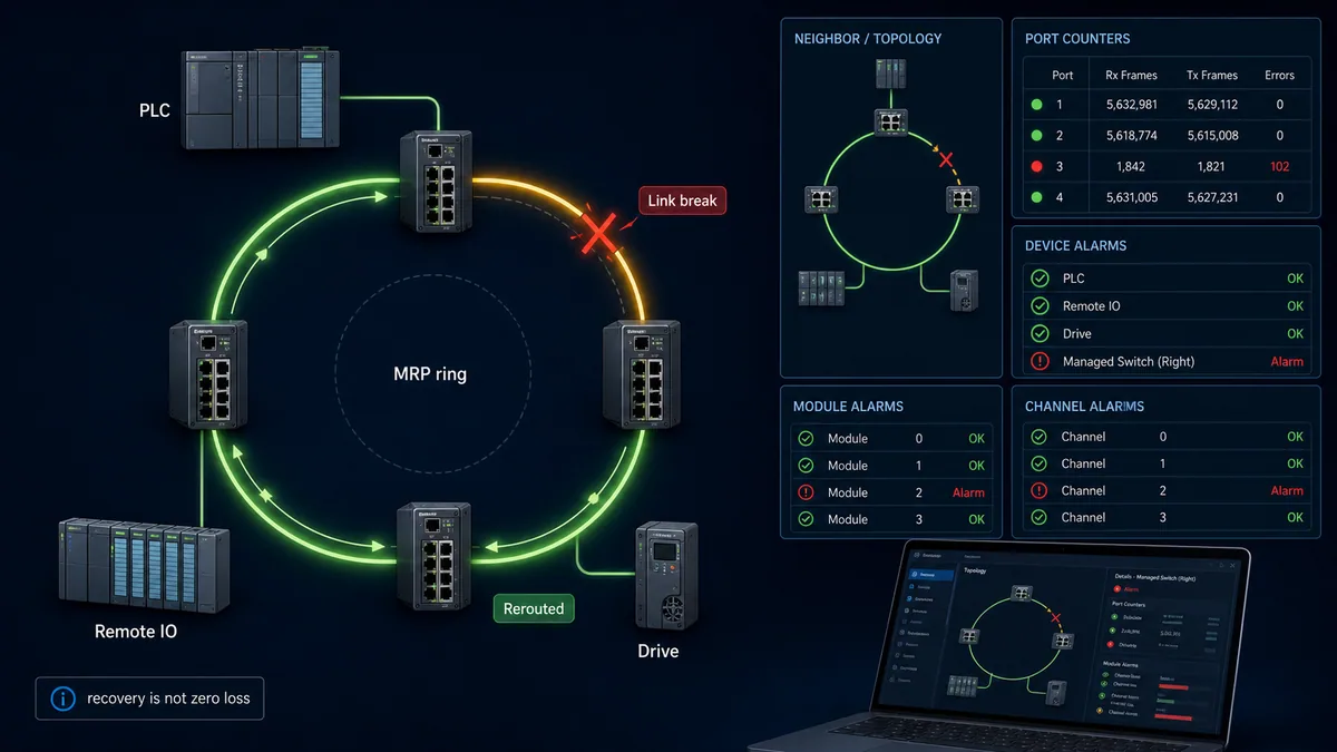
MRP uses a ring manager and clients to reconfigure the path after a supported media fault. Exact recovery class/time, participant limits and topology depend on the products and configuration. A ring protects a supported path fault; it does not duplicate controller CPU, device electronics, field power or every switch failure, and it does not make a process safe.
| MRP acceptance case | Observe | Pass criterion |
|---|---|---|
| healthy closed ring | manager/client roles, ring state and port neighbors | no loop/storm; expected manager and all participants recognized |
| open one approved link | ring diagnostic, reconvergence, AR/data status and task trace | recovery within designed threshold; process response matches specification |
| restore link | topology and manager state transition | stable return without duplicate path, repeated flapping or unintended device restart |
| fail non-ring spur/device | affected and unaffected nodes | only designed branch/device affected; ring is not credited for a non-ring failure |
| controller/device power loss | AR, outputs, alarms and recovery | engineered failure/startup behavior occurs; redundancy claim remains bounded |
| worst planned traffic | update jitter, port counters and watchdog | capacity and response remain within accepted limits during fault/recovery |
For applications that require bumpless IRT frame duplication, use only the specifically supported architecture such as MRPD where applicable; do not equate it with ordinary MRP. Validate through the relevant vendor and PI documentation.
Build layered diagnostics and troubleshoot by symptom
Start with the controller's relationship and data validity, then move outward to identity/configuration, topology/ports, module/submodule and channel diagnostics. Preserve first-out evidence because one upstream cable or power loss can create many downstream alarms.
Use an evidence hierarchy
| Level | Evidence | Example conclusion |
|---|---|---|
| controller/interface | controller running, correct physical adapter, task and stack state | local runtime/interface issue before device search |
| AR/device | connection state, PNIO status, station name, identity and data-valid flags | naming/configuration/timeout boundary |
| configuration | expected versus actual DAP, modules and submodules | GSDML, revision, wrong/missing module or slot difference |
| topology/port | LLDP neighbor, link events, counters and MRP state | physical path, switch configuration or intermittent media |
| module/submodule | inserted/owned/state and diagnostic record | exact rack/module boundary |
| channel | wire break, short circuit, over/underrange or device-specific code | exact signal or field circuit boundary |
| application | quality/data age, mapping, permissive and command handshake | PLC logic/interface issue after communication is healthy |
Work from symptom to discriminating check
| Symptom | First check | Likely next branch | Avoid |
|---|---|---|---|
| every PROFINET device offline | controller interface/task and first switch link | controller mode, adapter, upstream power/switch/VLAN | renaming every field device |
| one device offline | actual station name/MAC and AR status | duplicate/wrong name, power, local link, identity/configuration | assuming ping proves correct device |
| device reachable, module difference | expected versus actual slot/subslot tree | wrong GSDML/DAP/revision or physical module order | disabling checks until it connects |
| cyclic data runs but quality is bad | provider/consumer and submodule diagnosis | device parameter, module/channel fault, ownership | using last value as current |
| input LED changes, PLC tag does not | raw submodule bytes and mapping | address/direction/tag mapping or task refresh | replacing sensor first |
| drive shows ready but will not run | control/status word raw values and profile state | command ownership, enable sequence, interlock or drive fault | forcing an output bit outside handshake |
| intermittent losses | first event, task overrun and both-end port counters | connector/EMC/power dip/load/duplicate identity | resetting counters repeatedly |
| ring reports open but production continues | exact broken link and MRP state | maintenance repair while redundancy margin is lost | calling it healthy because data still flows |
| replacement visible but not configured | name transfer, identity/revision and module tree | factory state, wrong spare or topology precondition | copying old IP only |
| controller STOP causes device fallback | configured provider state/watchdog/substitute behavior | intended stop/restart policy and PLC I/O refresh | treating fallback as a device defect |
Capture timestamps from controller diagnostics, managed switches and device alarms using a controlled time source where possible. Compare both ends of a suspect link; a receive error at one end and clean transmit at the other can narrow the path. Packet capture can confirm discovery, AR setup and timing but should supplement—not replace—controller/device diagnosis and authorized network access.
Commission, replace and secure the system
Commissioning is complete only when valid process exchange, invalid/failure behavior and recovery all match the controlled design. Perform physical or process-affecting tests only under the site's electrical, hazardous-energy, process and safety procedures.
PROFINET acceptance matrix
| Gate | Test | Pass evidence |
|---|---|---|
| design baseline | review role, products, certifications, GSDML, firmware, topology, names/IP and timing | approved reproducible files and compatibility record |
| live discovery | scan intended network before assignment | every MAC/product/location accounted for; no duplicate/unplanned node |
| naming/addressing | assign/read back exact station name and verify controller IP behavior | one unique name per planned device; no address collision |
| configuration | compare DAP/modules/submodules and parameter records | expected equals actual with controlled parameter report |
| process mapping | test distinctive input/output/profile values one item at a time | raw data, quality, PLC tag and field/device indication agree |
| performance | run worst planned controller/network/device load | measured latency, jitter, counters and watchdog margin accepted |
| diagnostics | inject approved device/module/channel and link conditions | specific first-out alarm, location and application consequence shown |
| loss/fallback | interrupt relationship/link/power cases within authorized plan | data invalidation, output substitute and alarms match design |
| redundancy | open/restore each approved MRP fault case | recovery and process consequence within documented bounds |
| restart/replacement | restart controller/device and install approved spare in test/maintenance state | name/config transfer, identity checks and controlled resumption succeed |
| security/recovery | verify roles, access paths, backups, logging and supported secure settings | least necessary connectivity and tested recoverable configuration |
Use the industrial communication training path to rehearse layered network diagnosis and PLC/device data exchange before a plant change. The simulator cannot certify installed PROFINET timing, product compatibility, MRP recovery, cybersecurity, safety or physical installation. For the remote rack itself, see the PLC remote I/O modules guide. For a different deterministic Ethernet architecture, compare the EtherCAT PLC guide. The PROFINET versus Ethernet guide explains why the application protocol is more than ordinary Ethernet reachability.
Replace a device without losing identity evidence
Preserve the failed device's station name, MAC, IP, product/revision, GSDML, firmware, physical port/topology, module configuration, parameters, alarms and failure time before removal. Verify the spare's exact compatibility. Supported systems may restore a name through removable media or topology-based replacement, but this requires the documented controller/device conditions—often including a factory-state replacement and correct neighbor topology.
After replacement, prove identity, name/IP, expected modules, parameterization, raw data and quality, application mapping, failure behavior and process response. A green link LED and automatic data exchange are not sufficient acceptance.
Apply OT security to engineering and protocol access
PROFINET commissioning exposes powerful naming, configuration, diagnostic and sometimes web/SNMP services. Inventory them, segment the OT network, restrict engineering access to authorized hosts and roles, disable unnecessary supported services, manage vendor credentials/certificates where applicable, log changes and keep tested offline recovery material. NIST SP 800-82 Rev. 3 emphasizes security controls that preserve OT performance, reliability and safety requirements.
PROFINET specification 2.5 security work should not be represented as protection on legacy devices. Document the security capability actually negotiated/used by every controller, device and engineering path. Schedule product updates and security-mode changes through compatibility testing and management of change.
Diagnostic answer map for search and AI-assisted commissioning
| User or AI query | Concise answer | Required qualification |
|---|---|---|
| What is PROFINET in a PLC? | An industrial-Ethernet system where an IO Controller exchanges configured cyclic data and diagnostics with named IO Devices. | Ethernet link/IP reachability alone does not prove valid PROFINET I/O. |
| What is a PROFINET IO Controller? | Usually the PLC/runtime that configures devices, consumes inputs and provides outputs. | Verify the configured interface role; one product can support different modes. |
| Does a PROFINET device need an IP address? | It uses IP for applicable services, but controller startup identifies/configures the device through its PROFINET station name and project. | Initial local discovery/name assignment can occur before a final IP is present. |
| What is a GSDML file? | A vendor device-description file defining identity, modules/submodules, data, parameters, diagnostics and capabilities for the engineering tool. | Match exact product/DAP/revision/tool support; GSDML is not firmware. |
| Why can I ping a PROFINET device but not connect? | Ping proves limited IP reachability, not matching station name, identity, module configuration, AR or data status. | Read controller PNIO/device diagnostics and expected-versus-actual configuration. |
| How is PROFINET update time chosen? | From end-to-end process latency, device conversion, network load, controller I/O task, logic task and watchdog requirements. | Minimum selectable update is not automatically appropriate or achieved response. |
| What is MRP in PROFINET? | Media Redundancy Protocol restores a supported ring path after a media fault. | It is not universal zero-loss, controller redundancy, device redundancy or safety. |
| How are PROFINET I/O points addressed? | Through device API/slot/subslot process data mapped by the controller tool into tags/addresses with status. | Direction, byte layout and profiles come from exact GSDML/device documentation. |
| Can PROFINET carry safety data? | PROFIsafe can carry safety communication over supported standard networks. | It requires certified safety products, parameters and a validated functional-safety lifecycle. |
| What should I check first when one device drops? | Preserve first fault, then compare AR/status, name/MAC/identity, local link/topology, configuration and module/channel diagnosis. | Do not factory-reset before capturing as-found evidence. |
Frequently asked questions
Is PROFINET the same as Ethernet?
No. PROFINET uses Ethernet technology but adds a standardized automation model for IO Controllers, IO Devices, cyclic real-time data, device descriptions, slots/subslots, alarms, diagnostics and commissioning. Ordinary IP communication or Ethernet link status does not establish that model. See the PROFINET versus Ethernet guide for the protocol-layer comparison.
What is the difference between an IO Controller and IO Device?
The IO Controller normally runs the PLC program, consumes device input data and provides device output data. The IO Device is the field node that provides inputs, consumes outputs and exposes its module/submodule configuration. An IO Supervisor supports commissioning or diagnosis. Configure the exact supported role rather than relying on “master” or “adapter” shorthand.
Why does PROFINET use a device name as well as an IP address?
The station name gives the configured device a stable identity in the PROFINET system and lets the controller associate it with the project and apply/check IP parameters. IP addresses can change with project configuration. During first commissioning, a local tool commonly selects the physical node by MAC and writes the planned name.
Can I assign a PROFINET name across a router?
Normal engineering discovery/name assignment uses local Layer-2 DCP services and is commonly limited to the same subnet/broadcast domain; boundaries can intentionally stop that traffic. Use the product's supported commissioning architecture rather than expecting routed IP reachability to forward DCP Identify or Set operations.
What causes a PROFINET module difference fault?
The actual device reports a module/submodule arrangement or identity different from the controller's expected configuration. Common causes are the wrong GSDML/DAP or revision, a missing/wrong module, a module in the wrong slot, replacement compatibility or a device-side configuration mismatch. Compare the exact expected-versus-actual slot/subslot tree.
Is the PROFINET update time the same as PLC response time?
No. It is one stage. Sensor/filter and module conversion, network phasing, controller I/O task, application task, output update and actuator response all add delay and jitter. Build and measure the complete event-to-response path under worst planned load.
Does MRP prevent PROFINET communication loss?
MRP increases availability by restoring a path around a supported ring media fault. Ordinary MRP reconvergence can still affect cyclic frames and may interact with watchdogs. It does not protect a failed PLC, device electronics, power supply or non-ring branch. Test the exact ring and process consequence.
Do I need a special switch for PROFINET?
It depends on the required conformance, timing, topology, LLDP diagnostics, MRP/IRT or security functions and environmental design. A basic compatible switched network may carry general RT traffic, while richer features need explicitly supported/certified infrastructure. Select and test against the project requirement, not the word “industrial” alone.
Is PROFINET automatically secure?
No. Security depends on the specification/profile actually supported and enabled by the controller, device, tools and infrastructure, plus segmentation, access control, hardening, monitoring and recovery. New PI security specifications do not retrofit protection into legacy installations. Maintain an evidence-based asset and capability register.
Is ordinary PROFINET suitable for safety functions?
Ordinary process I/O is not a safety function. PROFIsafe can provide safety communication using certified controllers/devices and validated safety configuration, but it requires hazard analysis, safety requirements, approved products, signatures/parameters, verification and lifecycle controls. Do not infer safety from redundancy, fast update or a standard device's fail value.
Sources, review scope, and limitations
This guide was reviewed on August 28, 2026 against current public first-party documentation. PROFINET features and limits vary by specification/conformance, certification, controller, device, GSDML/DAP, firmware, engineering tool, switch, network load and project. Verify the exact installed combination and retain the tested documentation revision.
- PROFINET technology overview — PROFIBUS & PROFINET International
- PROFINET Technology and Application System Description — PI
- PROFINET Commissioning Guideline — PI
- PROFINET specification and version 2.5 overview — PI
- PROFINET System Description — Siemens
- Creating a GSDML device description — Siemens
- PROFINET protocol functionality — CODESYS
- PROFINET Controller architecture, tasks and GSDML — CODESYS
- PROFINET communication settings and watchdog — CODESYS
- PROFINET Controller troubleshooting — Beckhoff
- PROFINET station name, IP and module-difference diagnosis — Beckhoff
- NIST SP 800-82 Rev. 3, Guide to Operational Technology Security
The images are conceptual and do not define compatible devices, ports, terminal wiring, network capacity, timing, topology, MRP recovery, output fallback, cybersecurity controls or safety functions. This page does not authorize energized work, uncontrolled discovery/naming, output forcing, live packet interception, firmware changes, ring interruption or safety validation. Only qualified, authorized personnel following the site risk assessment, electrical and hazardous-energy procedures, manufacturer documentation, controlled network access, management of change and functional-safety lifecycle should configure or test an installed system.
Now run it · free to start
Follow plant data from sensor to SCADA
Fieldbus versus Ethernet, Modbus, EtherNet/IP, PROFINET, OPC UA and MQTT, then SCADA layers and alarms, taught on simulated equipment. Free to start.
Ownership disclosure: PLC Programming IO and PLC Simulation Software are operated by the same publisher.
PLC Programming IO Editorial Team
Industrial automation education, references, and software testing
The PLC Programming IO Editorial Team publishes sourced industrial-automation education and documents how material is reviewed, tested, and corrected. A team byline means the publisher is responsible for the page; it does not represent a fictional person or imply an engineering licence.
Coverage:
- • PLC programming concepts and examples
- • Vendor software tutorials and comparisons
- • SCADA, HMI, protocols, and instrumentation
- • Training, careers, and reference material
Review standard:
- • Prefer primary and official sources
- • Record software versions when material
- • Separate tested facts from estimates
- • Publish material corrections
Important scope note
This site provides education, not project-specific engineering approval. Safety, code, and compliance decisions require a qualified person with access to the actual machine and jurisdiction.