Modbus TCP Gateway and Converter: Selection, Modes and Setup
Choose, size, configure and prove a Modbus TCP gateway or converter by communication role, Unit-ID mapping, serial capacity, diagnostics and security boundary.
Review status: Editorially reviewed against the Modbus Organization application protocol V1.1b3, Modbus TCP messaging implementation guide V1.0b and serial-line guide V1.02; current official Moxa, Schneider Electric, HMS Networks and Advantech product documentation; and NIST SP 800-82 Rev. 3 OT-security guidance. Roles, modes, function support, connection limits, queue behavior, routing/remap, isolation, serial electrical requirements, environmental ratings, security functions, firmware, timing and acceptance remain converter-, device-, topology-, risk- and site-specific
Direct answer
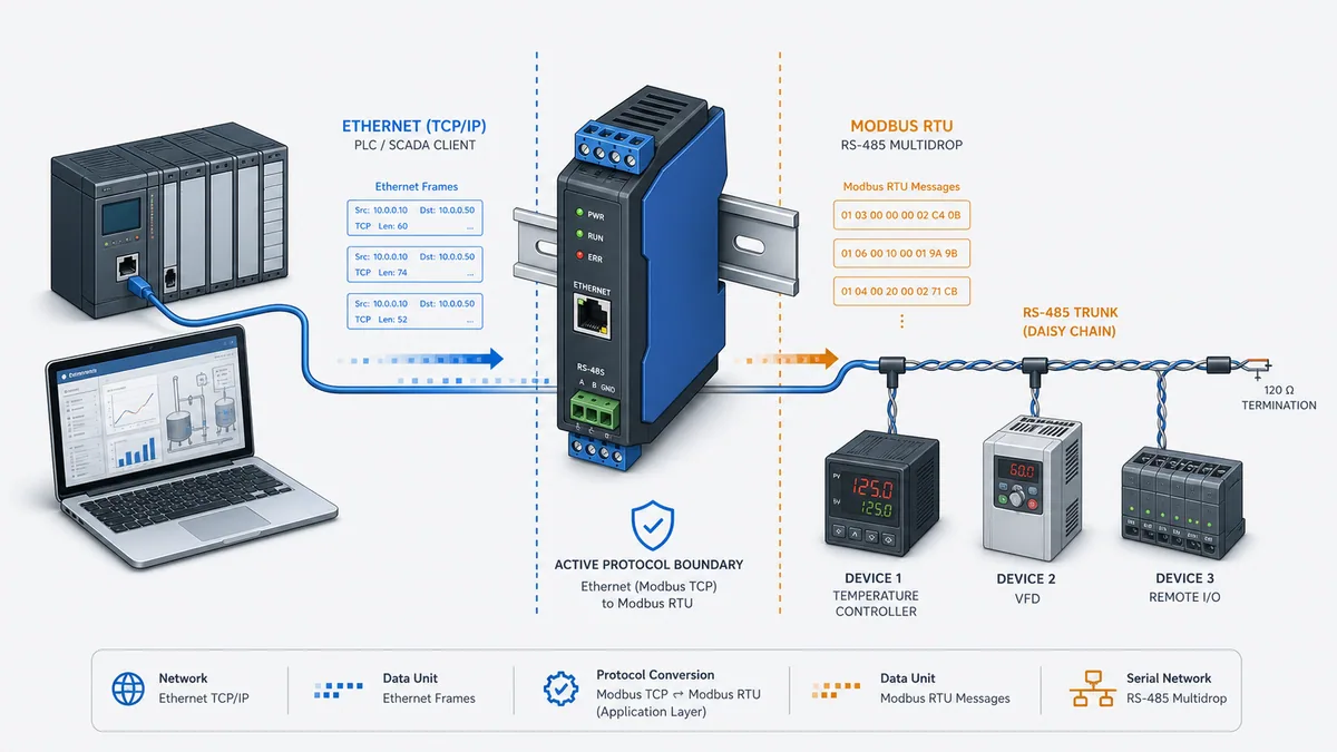
A Modbus TCP gateway, often sold under the interchangeable label Modbus TCP converter, is an active communication device or software service that lets endpoints using one Modbus transport exchange requests and responses with endpoints using another. In the common topology, a Modbus TCP client sends a request to the gateway's IP address and TCP port; the gateway uses the Modbus TCP Unit Identifier to select a downstream Modbus RTU server, removes the TCP-specific MBAP header, builds the serial RTU application data unit with address and CRC, arbitrates access to the serial bus, waits for the response, validates it and rebuilds the matching TCP response.
The label does not prove the operating mode. Some vendors call a transparent TCP-to-RTU bridge a gateway; others use gateway for a device that polls, caches or remaps data and converter for the transparent product. This page owns both terms because the selection task is the same: verify request direction, protocol awareness, Unit-ID routing, serial arbitration, timeout behavior, diagnostics and capacity from the exact manual.
In other words, a search for gateway Modbus RTU Modbus TCP or Modbus RTU Modbus TCP converter describes the same role-qualified selection and commissioning task. The word order does not tell you which endpoint is the client, whether the device transparently forwards a PDU, whether it polls and caches data, or whether it supports both request directions. Resolve those behaviors before choosing the enclosure.
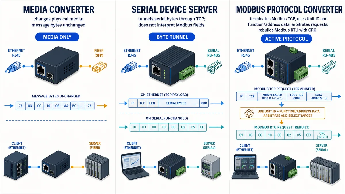
Do not buy from the words “RS-485 to Ethernet” alone. A media converter changes an electrical or optical medium. A serial device server tunnels serial bytes through TCP. An active Modbus protocol converter understands Modbus transaction boundaries, roles, Unit IDs, function codes, timeouts and serial request arbitration. These products solve different problems even when their enclosures expose the same RJ45 and screw terminals.
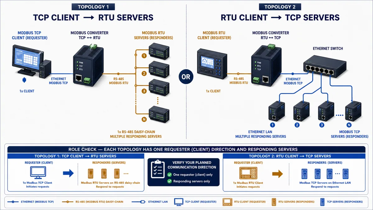
Define the required direction before selecting hardware: Modbus TCP client to Modbus RTU servers, Modbus RTU client to Modbus TCP servers, or an agent/mapped-data topology in which the converter polls one side and exposes an internal data table to the other. A product supporting the first direction does not automatically support the second. “Bidirectional” can refer to response traffic, not two interchangeable client roles.
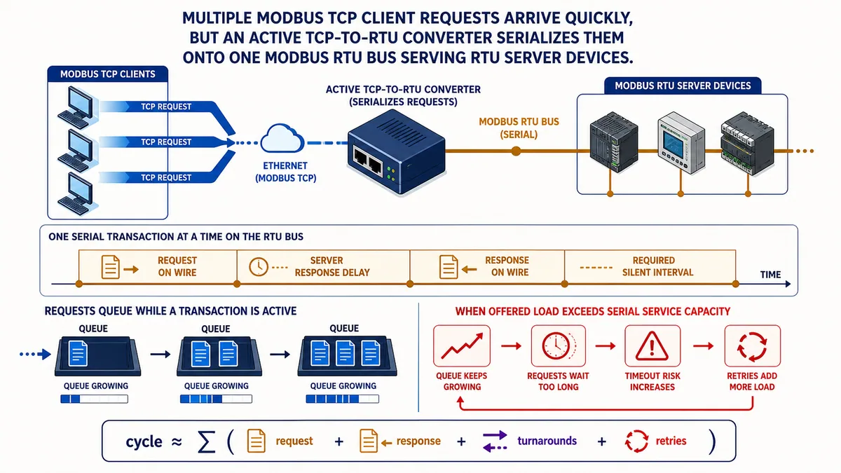
Size the converter from the slow side. Multiple Ethernet clients can submit requests faster than one RTU bus can serve them. Build a poll budget from request wire time, server response delay, response wire time, required inter-frame timing, converter turnaround, retries and engineering headroom. Then verify supported TCP connections, pending requests, serial ports, server addresses, routing/remap, function codes, diagnostics, isolation, environmental ratings, power, configuration backup and cybersecurity controls against the exact current manual.
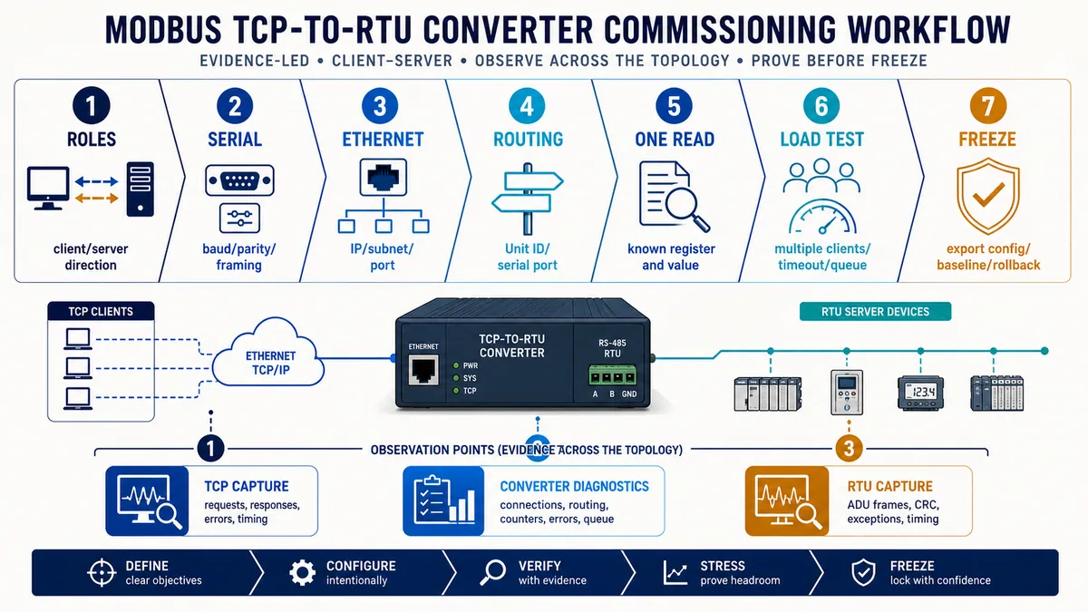
Commission one known read end to end before scaling the load. Capture the request at the TCP side, converter diagnostics and RTU side; prove IP/port, Transaction Identifier, Unit ID, function, protocol offset, quantity, serial address, baud/parity/framing, response, exception and interpreted value. A ping proves IP reachability only. An open TCP port proves a listener only. A valid Modbus response proves the exercised transaction, not every register, route, client or load case.
Use the downloadable gateway mapping contract, serial capacity worksheet and commissioning matrix to keep the route, data meaning, timing and evidence tied to one configuration revision.
Define the conversion job before choosing a device
Write the two endpoint contracts
Start with two endpoint records, not a catalog search. For each side record the physical interface, Modbus transport, communication role, address, supported public or vendor-specific function codes, register references, data types, update requirement, timeout behavior and diagnostic evidence available. Add power, isolation, enclosure, temperature, approvals and network-security requirements for the installation.
The phrase “PLC talks Modbus TCP” is incomplete. The PLC may be a TCP client that initiates reads, a TCP server that only responds, or both through separate resources. The serial device may be an RTU server, or an older controller may be an RTU client. Two clients cannot complete a request merely because a converter is between them; two passive servers cannot initiate one.
| Requirement | Endpoint A evidence | Endpoint B evidence | Converter consequence |
|---|---|---|---|
| Transport and physical port | Modbus TCP over Ethernet | Modbus RTU over 2-wire RS-485 | Needs active TCP/RTU conversion and the correct serial interface |
| Communication role | TCP client | RTU servers | Converter must accept TCP server-side connections and initiate RTU requests |
| Addressing | Gateway IP plus Unit ID | Unique RTU server address | Needs Unit-ID pass-through or a documented routing table |
| Data request | Function 03, protocol offset 99, two registers | Function 03 supported at that offset | Transparent translation may work without register remap |
| Update objective | Ten devices every two seconds | Known response-time distribution | Requires a measured poll and queue capacity budget |
| Failure behavior | Stale flag and alarm after approved delay | May return exception or not respond | Needs defined timeout, exception and last-value handling |
| Environment | Managed cabinet LAN | Field RS-485 in a panel | Check isolation, grounding, EMC, temperature, power and approvals |
| Security | Approved OT zone and named clients | Legacy unauthenticated serial devices | Treat converter as a security boundary; restrict management and request paths |
Separate conversion from business data ownership
A transparent TCP/RTU converter normally transports the Modbus Protocol Data Unit; it does not invent the register map, engineering units, byte order or control meaning. The PLC or SCADA request still needs the downstream device's exact register documentation. A mapped or agent-mode gateway may poll downstream registers into an internal memory map and expose different upstream addresses. That is a second data model that must be revision-controlled.
Name the required behavior explicitly:
- Pass-through/routing: Unit ID selects the downstream serial server and the PDU is preserved except for transport framing.
- Address remap: a virtual upstream Unit ID maps to a different serial port or RTU address.
- Register remap: upstream addresses map into a converter-owned data table or different downstream addresses.
- Agent/polling: the converter schedules downstream transactions independently and serves cached data upstream.
- Protocol conversion beyond Modbus: Modbus data maps to EtherNet/IP, PROFINET, BACnet, MQTT or another model; this is not a simple TCP/RTU bridge.
Each additional mapping layer can solve an integration problem but adds configuration identity, stale-data behavior, memory limits and another troubleshooting boundary.
Distinguish a protocol converter from similar products
Media conversion does not imply Modbus translation
A physical media converter can change copper Ethernet to fiber while leaving Ethernet frames conceptually intact. An isolated RS-485 repeater can regenerate the serial electrical signal. Neither necessarily parses an MBAP header or calculates an RTU CRC. Use them when the protocol is already compatible and only distance, isolation or medium must change.
A generic Ethernet/serial device server commonly encapsulates a serial byte stream in TCP or UDP. Paired virtual COM ports and raw socket modes can be useful, but the remote application must still produce and time the correct serial bytes. Multiple TCP connections, message boundaries and half-duplex arbitration may behave differently from an active Modbus gateway. Confirm the exact mode instead of assuming “transparent” means Modbus-aware.
Use a selection test that exposes the difference
Ask what happens when two TCP clients send overlapping requests to two RTU server addresses. An active converter should have documented behavior for connections, pending transactions, Unit-ID routing, serialization, timeouts and errors. A byte tunnel may simply forward byte streams according to a socket mode. A media converter has no Modbus transaction policy at all.
| Product type | Interprets Modbus fields? | Owns serial request timing? | Typical fit | Common selection mistake |
|---|---|---|---|---|
| Ethernet copper/fiber converter | No | No | Change Ethernet medium | Expecting it to expose an RS-485 Modbus device |
| RS-485 repeater/isolator | No | No | Regenerate or isolate a serial segment within product limits | Treating it as a TCP endpoint |
| Serial device server/raw tunnel | Usually no in raw mode | Mode-specific | Remote serial port or byte tunnel | Expecting Unit-ID routing and request arbitration |
| Modbus TCP/RTU protocol converter | Yes | Yes for supported topology | Connect Modbus transports with documented routing | Ignoring role direction and serial capacity |
| Mapped/agent gateway | Yes, plus internal mapping | Yes | Decouple scan schedules or convert data models | Forgetting cache age, mapping revision and quality |
| Software gateway | Implementation-specific | Yes when designed for it | Controlled host/edge platform with lifecycle support | Ignoring host availability, patching and interface ownership |
Choose the communication direction and operating mode
TCP client to RTU servers is common but not universal
In the common direction, an HMI, SCADA application or PLC is the Modbus TCP client. The converter accepts the TCP connection as the network-side server endpoint and issues the corresponding request as the RTU client on the serial bus. Downstream instruments, drives or I/O devices respond as RTU servers. The converter must serialize requests because a half-duplex serial bus cannot service multiple overlapping transactions as independent Ethernet sessions can.
The reverse use case starts with an RTU client that needs data from Modbus TCP servers. The converter must accept serial requests and initiate the right TCP request to a configured IP target. This needs a destination rule because an RTU address alone does not inherently contain an IP address. Some products support both directions; some support only one; some expose separate modes that cannot run together.
Agent mode changes freshness and failure semantics
An agent or polling gateway can read downstream devices on its own schedule and store values in internal memory. Upstream clients then read cached values instead of triggering a serial transaction for every TCP request. This can control serial load and isolate timing, but a successful upstream response may return an old value when downstream polling has failed unless age and quality are exposed and consumed.
| Mode | What triggers downstream traffic? | Upstream response source | Strength | Critical acceptance question |
|---|---|---|---|---|
| Transparent pass-through | Each accepted upstream request | Live downstream transaction | Simple mental model and direct exception path | How are concurrent requests queued and timed out? |
| Routed pass-through | Each upstream request after route selection | Live routed transaction | Multiple ports/segments or virtual IDs | What happens for missing/duplicate routes? |
| Agent/cached polling | Converter schedule or change rule | Internal data table | Controlled scan and upstream response time | How are stale age, comms failure and last value represented? |
| Register/protocol map | Configured transactions and transforms | Internal mapped objects | Bridges different address/data models | Who owns byte order, scaling, writes and mapping revision? |
| Raw serial tunnel | Host bytes or virtual COM traffic | Remote byte stream | Works with non-Modbus or proprietary serial traffic | Who guarantees frame boundaries, arbitration and RTU timing? |
Understand what happens to each Modbus message
Preserve the PDU and replace the transport wrapper
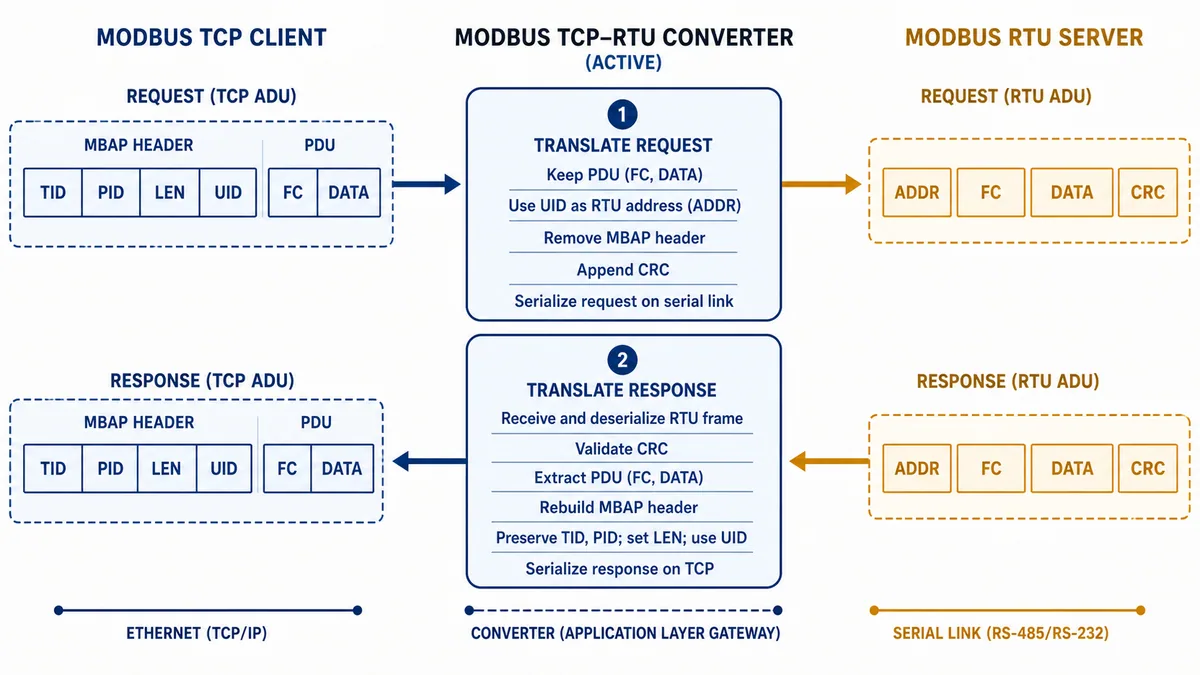
The Modbus Organization's TCP implementation guide describes a Modbus TCP Application Data Unit with an MBAP header before the Modbus PDU. The MBAP header includes a Transaction Identifier, Protocol Identifier, Length and Unit Identifier. The Transaction Identifier lets a client associate a response with its request. The Unit Identifier is especially relevant when a request must be routed through a bridge or gateway to a server on another bus.
An RTU frame instead carries the serial server address, function/data PDU and CRC. For a straightforward TCP-client-to-RTU-server translation, the converter associates the TCP transaction with the queued serial request, uses or maps the Unit ID to the serial address, transmits the function and data with RTU framing, validates the response CRC, then returns the response PDU under the correct MBAP fields. Product modes can add routing, mapping, caching or exception policies, so treat this as a reference model rather than a universal internal implementation.
Work one request at field level
Assume a TCP client sends Transaction Identifier 0x0042, Protocol Identifier 0, Unit ID 7, function 03, starting protocol address 99 and quantity 2. A pass-through converter route sends an RTU request to server address 7 containing function 03, start address 0x0063, quantity 0x0002 and a calculated CRC. The RTU server returns its addressed response and CRC; the converter validates the serial frame and builds the TCP response carrying Transaction Identifier 0x0042, Unit ID 7 and the response PDU.
The number 99 is a zero-based protocol address. A human-facing device manual may display the same first holding-register reference as 40001, 400001, 1 or another convention. The converter does not reliably resolve documentation notation for you. Verify the request bytes or diagnostic fields against the device manual and the client's address-entry convention.
| Evidence field | Example | What it proves | What it does not prove |
|---|---|---|---|
| Gateway IP and TCP port | 192.0.2.40:502 |
Intended TCP endpoint and listener | Correct Unit-ID route or downstream response |
| Transaction Identifier | 0x0042 |
Client can associate the returned TCP transaction | Register meaning or value correctness |
| Unit Identifier | 7 |
Requested routing identity in the TCP ADU | Exact serial target unless route policy is known |
| Function | 03 |
Read Holding Registers request | Device supports the requested address/quantity |
| Protocol start address | 99 / 0x0063 |
Exact on-wire starting offset | Whether documentation displayed 400100 or another notation |
| Quantity | 2 |
Two 16-bit registers requested | Float/int type, word order or scale |
| RTU address and CRC | 7, valid CRC |
Serial target/frame integrity for observed response | Correct physical process value |
| Returned data bytes | Four bytes | Payload actually returned | Engineering interpretation without type/order/scale evidence |
Design Unit-ID routing deliberately
Use pass-through only when identities are unambiguous
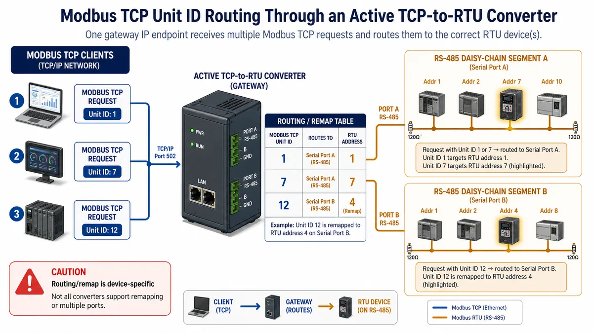
The TCP implementation guide assigns the Unit Identifier a routing purpose for a downstream serial or other subnetwork. A simple converter may pass Unit ID 7 to RTU address 7. A multiport converter may need a routing table because address 7 could exist on more than one isolated serial port. An advanced product may expose a virtual upstream Unit ID that maps to a different physical port and RTU address.
Do not assume that Unit ID 255, 0, 1 or any other value has the same direct-device and gateway meaning in every product. The Modbus guide recommends a non-significant value for a directly addressed TCP server, while vendor products and controller tools use documented conventions. For a converter, use the exact routing rules on both sides and include negative tests for an unmapped Unit ID.
Treat broadcasts and writes as separate hazards
Serial address 0 is defined for broadcast behavior in the serial-line guide, but whether a gateway forwards, processes, blocks or acknowledges a TCP-originated broadcast is device- and mode-specific. A Modbus write can change a physical process even when no response is expected on a serial broadcast. Default to blocking unrequired broadcasts and writes; enable them only under an approved control, cybersecurity and process-safety design with exact product evidence.
| Routing case | Expected policy to define | Acceptance evidence |
|---|---|---|
| Known Unit ID on one serial port | Pass through or explicit map | TCP request, selected port, RTU address and response all agree |
| Same RTU address on two ports | Port-disambiguating route | Each virtual Unit ID reaches only its intended segment |
| Unmapped Unit ID | Reject, discard or documented gateway exception | Deterministic result without traffic to an unintended port |
| Direct TCP server behind no serial route | Product-specific direct Unit-ID convention | Direct response and no unintended gateway routing |
| Broadcast Unit ID/address | Block or approved product-specific handling | Safe controlled test confirms scope; no assumed response |
| Write function | Allowlist and authorization policy | Intended address/value/function only, with process response observed |
| Route-table change | Version, approval and rollback | Exported configuration, diff, owner and post-change proof |
Live mini-lab
Try it: press START, then STOP
A stop-dominant seal-in rung: START latches the motor output through its own contact, and STOP breaks the circuit.
Watch the output lamp: it stays on after START until you press STOP.
Free to start · runs in your browserOpens plcsimulationsoftware.com — same team
Select hardware and software from an evidence matrix
Check the features that change system behavior
A purchasing table should distinguish advertised protocol names from operational limits. Record values from the exact ordering code, hardware revision, firmware and manual. “Supports Modbus TCP and RTU” does not answer how many TCP clients, pending requests, RTU servers, serial ports, routes, mapped bytes or polling transactions are supported—or what happens at those limits.
| Selection area | Questions to answer from current documentation | Why it matters |
|---|---|---|
| Direction and roles | Which TCP/RTU client and server combinations run, and simultaneously? | Avoids a converter that supports the protocols but not the required requester direction |
| Operating modes | Transparent, routed, agent, cache, remap, raw tunnel? | Determines data ownership, freshness and diagnostic model |
| Serial interfaces | RS-232/422/485, 2-wire/4-wire, connector and port count? | Must match the installed physical layer and segment design |
| Serial parameters | Required baud, data bits, parity, stop bits and RTU/ASCII support? | Every device on a serial segment must use compatible framing |
| Routing | Unit-ID pass-through, port selection, virtual IDs, remap and duplicates? | Determines how each TCP request reaches one serial server |
| Protocol functions | Used public and vendor-specific functions, maximum quantities and exceptions? | Prevents a basic read from hiding an unsupported production transaction |
| TCP resources | Client/server connections, requests per connection, queue and idle behavior? | Controls concurrency, recovery and capacity |
| Serial timing | Response timeout, inter-character/frame policy, delay and retry behavior? | Affects stability with slow or variable devices |
| Diagnostics | Traffic monitor, counters, logs, capture/export and clock? | Determines whether faults can be isolated without guessing |
| Electrical design | Isolation between ports/power, surge/EMC, grounding and termination provisions? | Controls common-mode, noise and fault propagation risk |
| Environment | Supply, power budget, temperature, enclosure, mounting and approvals? | Product suitability is installation-specific |
| Lifecycle/security | Supported firmware, signed updates, accounts, protocols, allowlists, logs, backup/restore? | Converter becomes a managed OT asset and trust boundary |
Score mandatory gates before desirable features
Use pass/fail gates for role direction, physical interface, environmental approvals, safety/risk constraints, required function codes and proven capacity. Only score convenience features after every gate passes. A low-cost converter that cannot expose a queue-full counter or preserve configuration revisions may cost more during an intermittent shutdown than a better-instrumented model.
| Criterion | Gate or score? | Example evidence | Reject when |
|---|---|---|---|
| Required topology works | Gate | Vendor mode diagram and bench transaction | Roles are reversed or ambiguous |
| Installed serial layer supported | Gate | Exact interface/wiring manual | Product is a raw RS-232 server for an RS-485 multidrop need |
| Capacity has headroom | Gate | Measured load test plus documented resource limit | Queue/timeout failure occurs below approved peak |
| OT security baseline | Gate | Account, service, update, backup and zone controls | Unmanaged exposure cannot meet site risk treatment |
| Diagnostic depth | Score after gates | Per-port traffic/counters and timestamped logs | Evidence stops at a single status LED |
| Configuration workflow | Score after gates | Offline file, diff/export, restore and rollback proof | Settings cannot be reconstructed after replacement |
| Lifecycle/support | Score after gates | Current firmware/manual and supplier policy | Exact model is unsupported or documentation unavailable |
Size the serial side before trusting Ethernet speed
Build a transaction-time budget
Ethernet link rate is rarely the governing capacity for a TCP-to-RTU converter. One half-duplex serial segment sends one request/response transaction at a time. The service time includes the request characters on the wire, required frame separation and turnaround, downstream server processing, response characters, converter processing and any retry. Multiple TCP clients can fill a converter queue while that one transaction completes.
For a first estimate, calculate character time from the configured serial format. A common 8E1 character has one start bit, eight data bits, one parity bit and one stop bit: 11 bits per character. At 9600 bit/s, one character takes approximately 11 / 9600 = 1.146 ms. An 8-byte request takes about 9.17 ms; a 9-byte response takes about 10.31 ms. The Modbus serial-line guide's RTU frame separation model uses at least 3.5 character times, which is about 4.01 ms in this example.
If the downstream device's measured response delay is 50 ms, a simplified successful cycle is at least:
9.17 ms request + 50 ms server delay + 10.31 ms response + 4.01 ms frame interval ≈ 73.49 ms
This is an engineering estimate, not a universal converter setting. It omits implementation-specific turnaround, Ethernet/converter processing, multiple frame intervals and jitter. Measure the actual distribution at normal and adverse load. Apply the current serial guide's timing rules and the exact converter/device manuals rather than copying this example.
| Poll-budget input | Example basis | Example time | Must be replaced with |
|---|---|---|---|
| Request length | 8 RTU bytes × 11 bits / 9600 bit/s | 9.17 ms | Actual function, quantity and serial format |
| Server response delay | Bench-observed representative delay | 50.00 ms | Measured typical and worst acceptable distribution |
| Response length | 9 RTU bytes × 11 bits / 9600 bit/s | 10.31 ms | Actual payload/error frame length |
| Frame/turnaround allowance | 3.5 character illustration | 4.01 ms | Applicable guide plus device/converter implementation |
| Successful cycle subtotal | Sum shown above | 73.49 ms | Measured end-to-end transaction time |
| Retry allowance | Not included in subtotal | 0 ms | Approved retry policy and failure probability |
| Engineering headroom | Not included | Project-specific | Load, jitter, diagnostics, growth and recovery objective |
Convert transaction time into a load decision
Ten devices each polled once per second at the simplified 73.49 ms service time require about 734.9 ms of serial service per second before other requests, retries or jitter: roughly 73.5% modeled utilization. That is not a recommendation or pass threshold. It demonstrates why a superficially small poll list can leave little recovery headroom. A slow server response can dominate even after baud rate increases.
For mixed requests, estimate each transaction separately and sum frequency × service time. Add scheduled writes, diagnostics, on-demand engineering traffic, multiple upstream clients, retry load and growth. Then run a representative load test. Measure queue depth, maximum/percentile response time, timeouts, exceptions, serial errors and freshness at the consumers. Confirm recovery after a server disappears and returns.
| Load-test case | Stimulus | Evidence to record | Pass condition to define before test |
|---|---|---|---|
| Normal steady state | Production poll list and expected clients | Response distribution, queue, errors, value age | All consumers meet approved freshness/error objectives |
| Peak concurrency | All allowed clients issue realistic overlap | Pending requests, rejection/queue behavior, latency | No silent data corruption; overload outcome is deterministic |
| One slow RTU server | Add approved response delay to one device | Impact on other routes and clients | Fault is contained within defined timing/recovery bounds |
| One absent server | Disconnect or suppress one safe bench device | Retries, gateway exception, queue recovery | Other required devices remain within their objectives |
| Malformed/unsupported request | Wrong function or quantity in controlled lab | Exception or rejection and counters | Safe documented response without unintended downstream write |
| Client reconnect storm | Reconnect allowed clients together | Connection/resource counts and recovery | Resource exhaustion does not leave converter wedged |
| Power/restart | Controlled approved restart | Boot time, configuration persistence, client recovery | Correct revision returns and stale data is not accepted as fresh |
Coordinate timeouts, retries and exceptions
Make the outer timeout longer than the proven inner path
A TCP client timeout should accommodate the approved converter queue plus serial transaction and response variation. If the client times out and retries while the original request remains queued, it adds load to the same bottleneck. Several clients with synchronized retries can turn one slow RTU server into a retry storm.
Document each layer: client response timeout, client retry count/backoff, converter downstream response timeout, converter retry policy, device processing limit, agent polling timeout, stale-data threshold and supervisory alarm delay. Avoid simply making every timeout “long.” Long hidden queues can return obsolete responses after the process context changed; short values can create needless retries.
Preserve the difference between protocol exception and no response
A valid Modbus exception response means a server or gateway returned a structured error PDU. A TCP connection reset, gateway timeout, serial CRC failure and silent device are different observations. The Modbus application protocol includes gateway-specific exception codes such as Gateway Path Unavailable and Gateway Target Device Failed to Respond, but exact converter use remains implementation-specific. Record the actual response bytes and product diagnostic rather than converting every failure into “Modbus timeout.”
| Observation at TCP client | Converter/RTU possibilities | Next discriminating evidence |
|---|---|---|
| TCP connect refused/reset | Service disabled, wrong mode/port, connection limit, ACL or restart | Converter service state, connection table and network capture |
| TCP response with exception bit | Downstream server exception or gateway-generated exception | Function/exception byte, Unit-ID route and converter log |
| TCP request followed by silence | Queue, downstream timeout, lost response, converter fault or filtering | Pending/queue counter, serial request/response capture |
| Valid response after client timeout | Outer timeout shorter than queue/path or retry overlap | Transaction IDs and end-to-end timeline |
| Wrong but stable value | Correct transaction with wrong address/type/order/scale, cached map or wrong route | On-wire fields, route table, raw bytes and data contract |
| Duplicate/late-looking response | Retry/transaction association, reconnect or application handling | TCP stream, Transaction Identifiers and client logs |
Configure the converter through an evidence-led workflow
Freeze inputs before touching settings
Create an interface control record with endpoint identities, roles, IP plan, serial settings, route table, function/address/quantity, data interpretation, poll rates, timeouts, write policy, quality behavior and owner. Record the converter ordering code, hardware/firmware, manual revision, MAC/asset identity and a rollback path. Back up the existing configuration before changing a brownfield device.
Carry out wiring, panel access and power work only under the applicable approved site electrical, hazardous-energy and network-change procedures. RS-485 signal terminals can still be exposed to damaging common-mode or induced conditions. Use the exact device wiring/isolation/grounding instructions and the site's competent persons; this article is not an energized-work procedure.
Prove one read, then expand in controlled increments
- Bench or isolate the topology under an approved change window.
- Verify the required client/server direction and select the corresponding converter mode.
- Configure one serial port from the downstream device evidence: physical interface, baud, data bits, parity, stop bits and RTU/ASCII mode.
- Configure the management and Modbus TCP network parameters under the approved IP plan; restrict unnecessary services.
- Add one explicit Unit-ID-to-port/address route if the mode requires it.
- Use one read-only request to a known changing or independently verifiable register.
- Compare TCP request/response, converter diagnostic, RTU request/response and the device's local/source value.
- Test a wrong Unit ID, unsupported address/function and absent server; record the exact safe outcomes.
- Add routes and transactions incrementally, then run the peak and degraded load cases.
- Export and checksum the approved configuration, label the asset, update drawings/records and retain rollback evidence.
| Commissioning checkpoint | Minimum evidence | Acceptance boundary |
|---|---|---|
| Identity | Model, firmware, asset ID, manual and configuration checksum | Matches approved bill/interface record |
| Roles/mode | Request-direction diagram and active mode export | One valid initiator path reaches intended responders only |
| Ethernet | IP/subnet, approved port/service, connection and ACL evidence | Required clients connect; unapproved path is denied per design |
| Serial | Interface, conductors, shield/ground reference, baud/parity/stop and traffic | Clean frames under installed conditions; no assumed wire labels |
| Routing | Every Unit ID, port and physical RTU address | Positive and unmapped negative route tests are deterministic |
| Data | Function, protocol offset, quantity, raw bytes, type/order/scale | Independent source agrees within defined process/data criteria |
| Timing/load | Poll inventory, response distribution, queue, retries and freshness | Normal, peak and degraded scenarios meet written objectives |
| Failure/recovery | Device loss, reconnect, restart and restored communication | Quality/age changes correctly; no silent stale acceptance |
| Handover | Export, checksum, diagrams, credentials custody, backup and rollback | Another authorized engineer can restore the approved state |
Design the RS-485 segment instead of treating it as two wires
Match the exact physical interface and topology
Modbus RTU is an application/serial framing choice; RS-485 is an electrical layer. Confirm 2-wire half-duplex versus 4-wire operation, terminal naming/polarity, reference/ground conductor requirements, cable, shielding, biasing, termination, stub limits, device count, segment length, isolation and surge/EMC provisions from current product and site standards. Do not rely on A/B, +/- or D0/D1 labels matching between vendors.
Use a trunk/daisy-chain topology where required by the segment design and keep branches within approved limits. Termination is typically associated with physical ends of an RS-485 trunk, but value, integrated termination and bias policies are product/network-specific. Power off or isolate as the approved procedure requires before changing connections. For deeper physical-layer diagnostics, use the dedicated RS-485 wiring guide.
Separate serial frame health from register correctness
Receiving valid CRC frames proves the observed serial messages were framed consistently; it does not prove the request used the right register or that the device value is correct. Conversely, repeated CRC/framing errors point toward the serial boundary—wiring, reference, topology, noise, baud/parity/framing or transceiver conditions—before register scaling.
| RTU-side observation | Most relevant boundary | Evidence to collect safely |
|---|---|---|
| No request transmitted | Converter mode, route or queue | Route decision, port state, request counter and TCP fields |
| Request sent to wrong address | Unit-ID mapping/routing | TCP Unit ID versus RTU address and route revision |
| Request seen, no response | Target, serial path or unsupported request | Local device state, address/framing, function/address and bus capture |
| CRC/framing errors | RS-485 electrical/serial configuration | Error counters, waveform/tool evidence, topology and settings |
| Exception response | Server understood a request and rejected/failed it | Exact function/exception and device manual |
| Correct raw response, wrong HMI value | Data interpretation after transport | Offset notation, byte/word order, type, scale and tag mapping |
Treat the converter as an OT cybersecurity boundary
Do not expose classic Modbus TCP merely because conversion works
The Modbus Organization publishes a separate Modbus Security protocol that uses TLS and X.509 certificates on registered port 802. That does not mean an installed converter implements it, nor does changing the classic port provide equivalent security. Determine the exact product capability and site architecture.
NIST SP 800-82 Rev. 3 recommends securing OT while preserving safety, reliability and performance. For this use case, place the converter in the intended OT zone, allow only required communication paths, restrict management access, change supported default credentials, disable unused services, maintain time/logging, back up configuration, manage firmware and test recovery. A dual-port converter is not automatically a firewall or safely segmented architecture.
| Control surface | Design question | Evidence at acceptance |
|---|---|---|
| Network zone | Which trust domains does the converter join? | Current network/data-flow diagram and approved boundary placement |
| Data service | Which clients, servers, ports, Unit IDs and functions are required? | Allowlist/firewall/request policy plus negative test |
| Management | Who can discover, configure, reboot or update it, and from where? | Named path, accounts/roles, protected credentials and audit trail |
| Unused services | Are web, discovery, SNMP, Telnet/SSH, cloud or vendor tools required? | Disabled/restricted service inventory verified after restart |
| Firmware | Is the exact release supported and integrity-checked? | Supplier source, approved version, change record and rollback |
| Configuration | Can approved state be exported, compared and restored? | Protected backup, checksum, restore test and ownership |
| Monitoring | Are connection, route, serial and security events observable? | Timestamped log/counter collection and alert ownership |
| Failure mode | What happens on reboot, network loss or serial loss? | Tested quality/stale/control behavior and safe recovery sequence |
Restrict writes by design and validate process consequences
Function-code filtering is useful only if the product implements it in the active data path and the policy matches the application. A read-only commissioning tool should not have an unexplained path to write coils or registers. When writes are required, define allowed clients, Unit IDs, functions, addresses, value/range validation, operating modes and audit evidence. Network controls complement—not replace—PLC/process interlocks, machinery safeguards or safety systems.
Troubleshoot by boundary and exact symptom
Start at the first failed observable transition
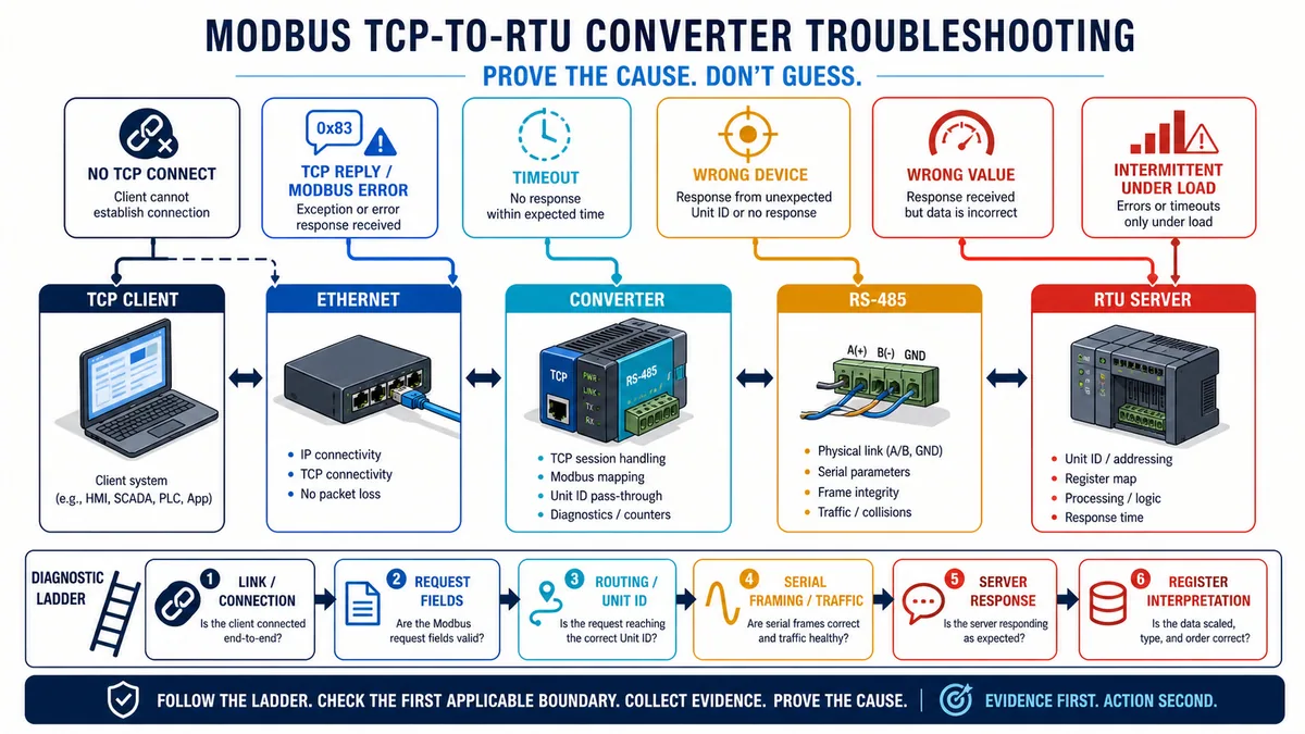
State the symptom precisely: cannot establish TCP; connection succeeds but no Modbus response; valid exception; wrong device; wrong raw bytes; wrong interpreted value; intermittent timeouts only under load; or stale cached value. Record start time, affected clients/routes, recent changes, converter mode/configuration checksum, error counters and process state before rebooting or changing settings.
Trace one transaction from left to right. At the TCP client, record destination, connection, Transaction ID, Unit ID, function, protocol address and quantity. At the converter, record accepted/rejected request, selected route/port, queue, timeout and exception. On the serial side, record address, function, data, CRC/frame health and response timing. At the consuming application, verify data type, byte/word order, scale, quality and age.
Use the symptom-to-evidence matrix
| Symptom | Plausible causes | Highest-value next checks | Avoid |
|---|---|---|---|
| Cannot open TCP connection | Wrong IP/subnet/port, service/mode down, ACL, connection limit, duplicate IP | ARP/path evidence, TCP SYN outcome, service and connection counters | Changing serial baud before TCP exists |
| TCP connects, all Unit IDs time out | Wrong converter direction, serial port down/misframed, route absent, bus fault | Active mode, transmit counter, RTU request capture and port errors | Assuming every downstream device failed together |
| One Unit ID times out | Wrong/duplicate route, server address/config, local wiring or device offline | Compare working route, RTU request address and local device state | Rebooting the whole network first |
| Valid gateway exception | Path/target/resource condition as implemented by product | Exact exception, queue/route log and product manual | Calling every exception a CRC error |
| Wrong device responds | Unit-ID remap, duplicate address, wrong serial port or undocumented direct-server convention | TCP UID, route table, RTU address and physical segment | Fixing value scaling before identity |
| Correct server, illegal address exception | Display-reference versus protocol-offset error, unsupported range/quantity/function | Manual map revision and exact request PDU | Adding/subtracting one repeatedly without bytes |
| Raw bytes correct, engineering value wrong | Type, signedness, endian/word order, scale or stale mapping | Raw byte decode against one known value and data contract | Blaming the converter's electrical layer |
| Works with one client, fails with several | Queue/connection/pending limit, timeout and retry amplification | Connection/pending counters, serial utilization and transaction timeline | Increasing retries without a load budget |
| Values freeze but TCP replies continue | Agent cache stale, downstream poll failed, last-value policy | Cache age/quality, agent transaction state and local changing reference | Treating a plausible cached value as healthy |
| Intermittent CRC/framing errors | Serial topology/reference/noise, loose termination, baud/framing mismatch | Safe physical inspection, error counters, capture/scope by qualified staff | Using TCP ping as serial proof |
For related failure interpretation, use the focused guides for Modbus timeout, CRC and no-response faults, Modbus function and exception codes and Modbus register addressing.
Decide when not to use a converter
Prefer a native interface when it removes a failure boundary
A native, supported Modbus TCP interface may be better when the device offers it with adequate diagnostics, lifecycle and cybersecurity controls. A converter is justified when it preserves a supported asset, creates required isolation/routing, consolidates a serial segment or provides a controlled protocol boundary. It is not automatically the cheapest lifecycle choice once configuration, spares, security, monitoring and fault-finding are included.
Do not insert a generic converter into a safety-related or tightly time-critical control path merely because basic register reads work. Determine whether latency, jitter, diagnostic coverage, common-cause failures, systematic capability, environmental approval and lifecycle meet the applicable risk assessment and standards. Standard Modbus polling through a commercial gateway does not become a safety communication channel without a validated safety architecture.
| Situation | Converter decision | Reason |
|---|---|---|
| Supported native TCP interface meets requirements | Prefer native unless another boundary is justified | Fewer configured layers and failure points |
| Legacy RTU instruments remain supportable | Converter may be appropriate | Extends controlled integration without replacing all field assets |
| Two clients compete for one slow serial bus | Use only with proven arbitration/capacity or redesign | Converter cannot remove serial service limits |
| Required data needs complex remap/cache | Use mapped gateway only with quality/age governance | Internal data table becomes a controlled source |
| Internet or untrusted cross-zone exposure requested | Redesign with OT security architecture | A basic Modbus converter is not a sufficient trust boundary |
| Safety trip or deterministic motion depends on it | Specialist validation or different architecture | General-purpose gateway behavior is not automatically safety/deterministic |
| No current manual/firmware/support path | Reject | Configuration and risk cannot be maintained responsibly |
Diagnostic answer map for Modbus TCP converter questions
If someone asks what a Modbus TCP converter does
Answer with the active boundary: it receives a Modbus transaction on one transport, routes and serializes it according to configured roles, rebuilds the other transport frame, associates the response and exposes a documented error outcome. Then distinguish protocol conversion from media conversion and byte tunneling.
If someone asks whether an RS-485-to-Ethernet device will work
Ask whether it is a raw serial device server or a Modbus-aware gateway, which side initiates requests, how Unit IDs map, who owns RTU timing, and whether concurrent TCP requests are arbitrated. Matching connectors and baud rate do not establish protocol compatibility.
If someone asks how to choose a converter
Require a topology/role diagram, used functions and address conventions, serial/electrical interface, route behavior, poll/load budget, diagnostics, isolation/environment, configuration recovery and OT security/lifecycle evidence. Gate on required behavior before comparing convenience or price.
If someone asks why the converter works for one device but not another
Compare Unit-ID route, serial address/framing, supported function/address/quantity, device response time and physical segment evidence. Capture the working and failed requests at the TCP, converter and RTU boundaries; change one proven difference at a time.
If someone asks why timeouts appear only with several clients
Look for the fast-arrival/slow-service queue: TCP concurrency, pending-request limit, one-at-a-time RTU service, downstream delays and retry amplification. Measure queue and serial transaction timing before increasing timeouts or retries.
If someone asks where to practise before commissioning
Use the interactive Modbus simulator to rehearse request fields, register offsets, responses and fault evidence. A browser lab teaches the diagnostic method; it does not reproduce the exact converter firmware, electrical layer, load or site risk.
Frequently asked questions
What is the difference between a Modbus TCP converter and a gateway?
Vendors often use the terms interchangeably. Verify behavior rather than the label. For this guide, an active converter/gateway terminates or interprets Modbus transport framing, routes requests and rebuilds messages between supported sides. Some gateways also poll, cache or remap data; some “converters” are only media or byte tunnels.
Can one Modbus TCP converter connect multiple RTU devices?
Often, when the product supports an RS-485 multidrop server segment and the installed network meets its electrical, address, timing and capacity limits. Do not equate the protocol address range with the converter's supported device count. Confirm exact manual limits and prove the planned poll/load case.
Does the Modbus TCP Unit ID equal the RTU server address?
It can in a transparent pass-through route, but not universally. Multiport, virtual-ID or remapped configurations can translate Unit ID to a different port/address. Direct TCP servers also use product/controller-specific Unit-ID conventions. Inspect the configured route and on-wire RTU address.
Is a serial device server the same as a Modbus TCP-to-RTU converter?
No. A raw serial device server tunnels a byte stream and may not understand Modbus transactions, Unit-ID routing, CRC generation or concurrent-request arbitration. Some products offer both raw and Modbus-aware modes, so identify the active mode and its documented behavior.
Why is a Modbus TCP converter slow when Ethernet is fast?
The RTU segment is serialized. Each request consumes request wire time, server delay, response wire time, frame/turnaround timing and sometimes retries. Multiple TCP clients queue behind that service path. Build and load-test a serial transaction budget instead of using Ethernet link speed as throughput evidence.
Which TCP port does a Modbus converter use?
Classic Modbus TCP conventionally uses registered port 502. The Modbus Organization's separate Modbus Security protocol uses port 802. Products may expose configurable or additional management ports. Use the exact approved configuration and firewall policy; a nonstandard port is not authentication or encryption.
How do I test a Modbus TCP-to-RTU converter?
Start with one read-only request to a known register. Record the TCP destination, Transaction ID, Unit ID, function, protocol address and quantity; converter route/queue; RTU address/frame/response; and independently verified value. Then test unmapped ID, unsupported request, absent server, peak load, reconnect and restart recovery.
Why do I get the correct response but the wrong value?
Transport can be correct while interpretation is wrong. Check register-reference versus zero-based protocol offset, quantity, data type, signedness, byte/word order, scale, units and cache age. Compare raw response bytes with one controlled or independently known value before editing mapping logic.
Can a converter isolate two OT networks securely?
Not by assumption. Isolation ratings, dual Ethernet ports and protocol translation do not automatically make a firewall or security boundary. Use the site's OT architecture, allow only required paths, restrict management, harden the supported product, monitor it and validate failure/recovery under NIST and organizational guidance.
Can I use a Modbus TCP converter for safety control?
Not merely because it exchanges values. Safety use requires an applicable risk assessment and validated architecture covering systematic capability, diagnostics, timing, independence, failure response, proof testing and lifecycle. A standard converter and conventional Modbus polling should not be described as a safety channel without that evidence.
Sources, review scope, and limitations
Primary sources used for this guide
- Modbus Organization specifications and implementation guides: official index for the application protocol, TCP messaging, serial-line and Modbus Security specifications.
- Modbus Application Protocol Specification V1.1b3: public functions, PDU, exceptions and gateway exception definitions.
- Modbus Messaging on TCP/IP Implementation Guide V1.0b: MBAP fields, Transaction Identifier, Unit-Identifier routing, TCP client/server and gateway reference behavior.
- Modbus over Serial Line Specification and Implementation Guide V1.02: RTU/ASCII framing, serial addresses, timing and physical-layer guidance scope.
- Modbus TCP Conformance Test Specification V3.0: direct-server and downstream-serial Unit-Identifier test context and function/reference disclosure.
- Moxa MGate MB3170/MB3270 current support page and MGate MB3000-G2 manual: product-specific mode, routing, multiport and diagnostic examples; not universal limits.
- Moxa MGate MB3660 manual: product-specific queue, dropped-request, route and response-timeout examples.
- Schneider Electric Modbus gateway definition and current Ethernet gateway implementation: current official client/server terms, Unit-ID forwarding and product-specific gateway configuration.
- Schneider Electric Modbus TCP cyclic exchange configuration: Unit-ID gateway routing and function-specific request-length examples in that controller environment.
- HMS Networks Communicator configuration and serial protocol settings: official product-specific node, transaction, data-map and mode workflow examples.
- Advantech EKI-1200 Series user manual: current product-specific transparent/agent mode and configuration context.
- NIST SP 800-82 Rev. 3: current final US guidance for securing operational technology while addressing performance, reliability and safety requirements.
- OSHA 1910.147 hazardous-energy control and OSHA 1910.333 electrical work practices: US isolation and electrical work-practice boundaries in their scope.
Review and safety limitations
This guide provides a vendor-neutral selection, capacity, setup and diagnostic framework. It is not a product approval, network/security architecture, serial electrical design, control-system risk assessment, functional-safety validation, hazardous-area assessment, energized-work instruction or promise of interoperability. The worked timing model is illustrative; real character format, message size, required intervals, server delay, converter implementation, jitter, queue, retry and load must be measured and accepted for the installed system.
The eight original generated visuals are educational abstractions. Port labels, wiring, termination symbols, routes, packet fields and device counts do not replace current manuals, engineered drawings or qualified review. Product examples establish possible behavior only for the cited family/version; they do not make queue size, connection count, routing, remap, isolation, security, timing or diagnostic features universal.
Use exact current documentation for every endpoint and converter ordering code/firmware, approved site drawings and cybersecurity/change procedures, suitable test tools, controlled read/write permissions and qualified automation, network and electrical authority. Revalidate after changes to roles, client count, poll list, Unit IDs, serial ports/settings/topology, register maps, byte order/scaling, timeouts/retries, firmware, network zones, security controls, process use or recovery requirements. Review this page whenever a cited specification, security publication or product document changes.
Now run it · free to start
Learn Modbus, then the networks around it
Modbus first because it is simple and everywhere, then the Ethernet-based protocols and the SCADA layer above them. Free to start.
Ownership disclosure: PLC Programming IO and PLC Simulation Software are operated by the same publisher.
PLC Programming IO Editorial Team
Industrial automation education, references, and software testing
The PLC Programming IO Editorial Team publishes sourced industrial-automation education and documents how material is reviewed, tested, and corrected. A team byline means the publisher is responsible for the page; it does not represent a fictional person or imply an engineering licence.
Coverage:
- • PLC programming concepts and examples
- • Vendor software tutorials and comparisons
- • SCADA, HMI, protocols, and instrumentation
- • Training, careers, and reference material
Review standard:
- • Prefer primary and official sources
- • Record software versions when material
- • Separate tested facts from estimates
- • Publish material corrections
Important scope note
This site provides education, not project-specific engineering approval. Safety, code, and compliance decisions require a qualified person with access to the actual machine and jurisdiction.