Modbus Timeout, CRC Error and No Response Troubleshooting
Separate Modbus timeouts, CRC and framing errors, valid exception replies, TCP connection failures and gateway faults with a repeatable evidence-led workflow.
Review status: Editorially reviewed against the Modbus Organization application, serial-line and TCP messaging specifications and current Siemens and Schneider Electric implementation and diagnostics documentation; installed device manuals, approved network drawings, risk assessment, cybersecurity rules and controlled test procedures govern the actual system
Direct answer
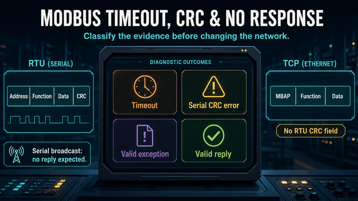
A Modbus timeout means the client did not accept a complete matching response before its timer expired. It is an observation, not a root cause. The request may never have left the client, the server may never have received it, a serial receiver may have discarded a frame with parity, length or CRC damage, the server may be busy, a gateway may be waiting on its downstream network, a reply may have been addressed or correlated incorrectly, or the response may simply have arrived after the configured deadline.
A valid Modbus exception response is not a timeout. It proves that a responding endpoint received and parsed enough of the request to return the original function code with its most significant bit set and an exception code. Diagnose that outcome at the application layer with the requested function, address, quantity and server data model. Use the dedicated Modbus function and exception code guide for exception meanings.
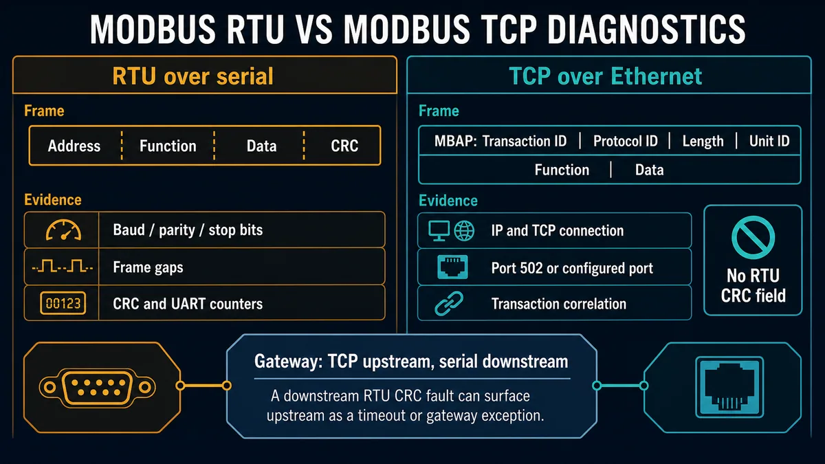
A CRC error belongs to Modbus RTU framing, not the Modbus TCP application data unit. A serial receiver normally discards a CRC-invalid request rather than answering it, so the sender may record only a timeout while the receiving device increments a CRC or invalid-message counter. Conversely, a client that receives a damaged RTU reply may increment its own CRC counter. Counter location therefore matters. Modbus TCP uses an MBAP header and TCP transport; a TCP-to-RTU gateway can still encounter CRC faults on its downstream serial side.
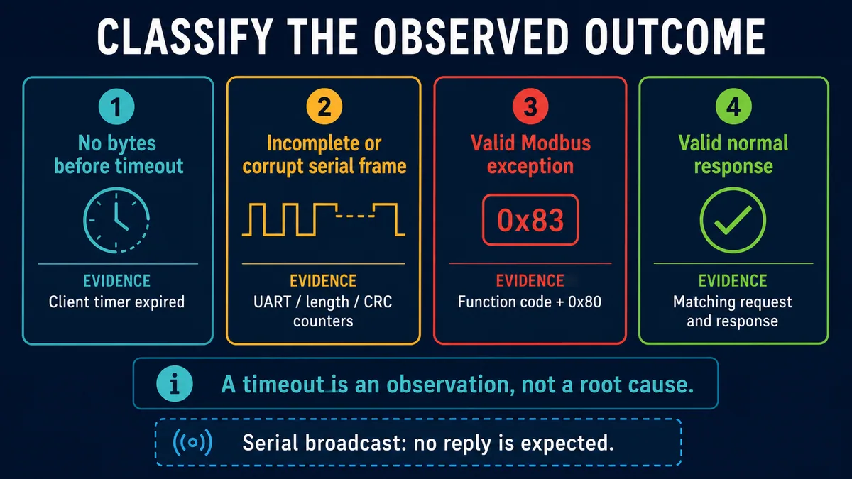
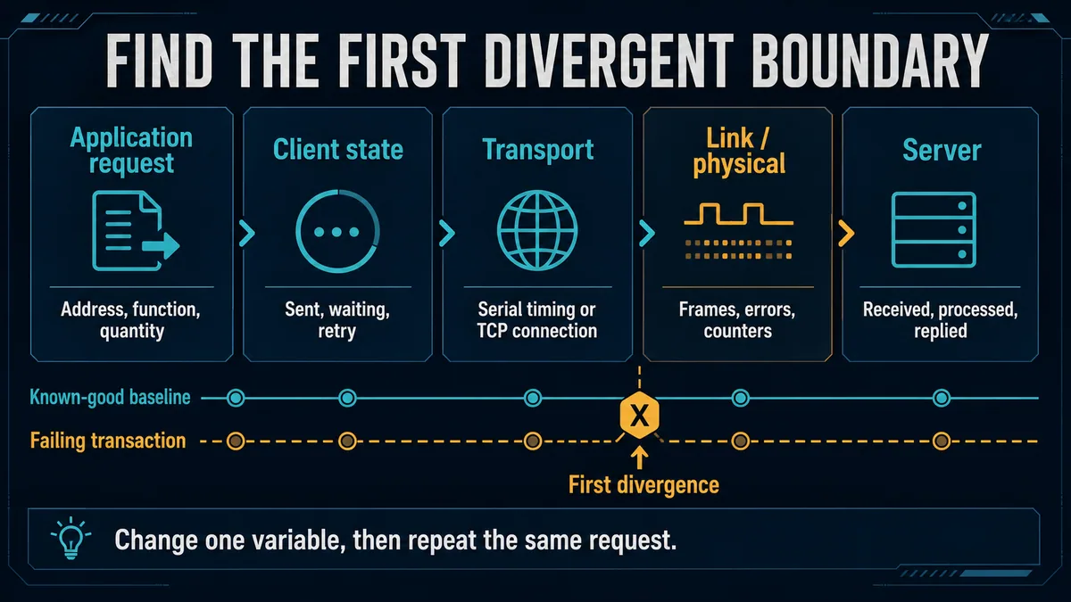
Classify the observed result before changing anything: no bytes, incomplete or corrupt serial data, valid exception response, or valid normal response. Record the exact request and the first diagnostic counters, repeat one controlled transaction, and find the first boundary where the failing path diverges from a known-good path.
Establish a safe and repeatable test boundary
Preserve process state before forcing communications
A read request can still increase network load, expose stale assumptions or interact with a controller task that consumes communication data. A write can change a setpoint, command, recipe, mode or output. Obtain the authorization required for the plant and use a test server, simulator, isolated segment or documented read-only point whenever possible. Do not bypass protection, energize equipment, interrupt a required control link or disconnect a live bus simply to make a capture easier.
Record the controller, server, gateway, client and network configuration revisions before editing them. Preserve screenshots or exports of the failing transaction, diagnostic counters and timestamps. If the link is intermittent, the first evidence may be the only evidence that preserves the original condition.
| Boundary to record | Minimum evidence | Why it matters |
|---|---|---|
| process and machine state | mode, running/stopped state, active maintenance and relevant interlocks | separates communications symptoms from a state-dependent server behavior |
| client | software/firmware version, channel, request schedule, timeout and retry values | identifies who declares the timeout and how load is created |
| request | transport, endpoint, unit/server address, function, starting address, quantity and write payload | makes each repetition comparable |
| path | ports, switches, serial adapters, isolators, radios and gateways | reveals translation and buffering boundaries |
| server | model, firmware, configured address and enabled services | anchors behavior to the installed implementation |
| time | common time reference, local time zone and observed clock offsets | permits event and capture correlation |
Create one transaction identity
“The HMI cannot read the meter” is not a reproducible test. Define one transaction: for example, client A sends function 03 to configured Unit Identifier 7, starting at the documented protocol address, requesting two registers, every two seconds. For Modbus TCP, record the destination IP, configured TCP port and MBAP Transaction Identifier. For RTU, record the physical interface, slave address, mode, baud rate, parity, data bits and stop bits.
Choose a documented, non-destructive request that succeeds on a known-good client if one exists. Repeat the same request while changing one variable. A scan containing dozens of mixed requests hides whether the failure follows one device, one function, one address span, one poll interval or the transport itself.
Classify timeout, corruption, exception and valid reply
Treat the four outcomes as separate branches
The first useful split is not “software or wiring.” It is the response class. A client that sees no bytes has different evidence from a client that receives bytes but rejects them. A valid exception has different ownership from a corrupt frame. A valid reply with wrong-looking values is usually an addressing, data-type or interpretation question rather than a transport timeout.
| Observed outcome | What it establishes | What it does not establish | Next evidence |
|---|---|---|---|
| no received bytes before timeout | the client accepted no response data in time | that the cable, server or address is definitely wrong | transmit evidence, peer receive counter, path status and timing |
| incomplete frame | some serial bytes arrived but the expected frame did not complete | whether bytes were truncated at source, adapter or receiver | byte count, UART errors, inter-character timing and capture |
| CRC-invalid RTU frame | a receiver computed a different CRC for received serial content | that the server application processed the request | counter owner, direction, raw bytes and physical/timing evidence |
| valid exception | a server/gateway returned a syntactically valid exception response | that the requested address, function or current server state is valid | exception code, exact request and server documentation |
| valid normal response | request and response matched at the protocol layer | that register interpretation, byte order, scale or freshness is correct | data map, type, word order, units and source update |
| TCP connection failure | the client could not establish or retain the transport session | that Modbus application settings are correct or incorrect | route, IP, configured port, listener, firewall and connection trace |
Check whether a response was expected
In Modbus serial line operation, address zero is used for broadcast. Servers execute a supported broadcast write without returning a response. A client that starts a normal response timer for its own deliberate broadcast can manufacture a false alarm. Broadcast behavior, supported functions and address rules must be checked against the serial specification and product manual.
Also identify gateway-generated behavior. A gateway may return a Modbus gateway exception, close a TCP connection, delay until its downstream serial timeout, or expose only a vendor diagnostic. Do not describe every upstream silence as the end device's behavior until the downstream transaction is observed.
Prove the exact request before inspecting the cable
Verify identity, function, address and quantity
A server cannot answer the transaction the technician intended; it answers the bytes it received. Capture or log the on-wire request. Compare the unit/slave address, function code, starting protocol address, requested quantity or byte count, and payload with the server manual. Human-facing labels such as 40001 may include a reference-type prefix that is not transmitted. The protocol data address in a function 03 request is a zero-based field. Use the Modbus registers and addressing guide to resolve notation and word-order issues after transport is known good.
If one request fails while another to the same device succeeds, keep the working request as a control. Compare only the changed fields. A valid exception for the failing range strongly shifts the investigation toward the data model, permissions, device state or function support. Silence for only one function can still be implementation-specific, but it should be proven with server diagnostics rather than assumed.
| Request field | RTU evidence | TCP evidence | Frequent mismatch |
|---|---|---|---|
| server identity | slave address byte | MBAP Unit Identifier plus IP endpoint | wrong address, duplicate serial address or gateway routing map |
| operation | function code | function code after MBAP header | unsupported read/write function |
| data location | PDU starting address | PDU starting address | display reference confused with protocol offset |
| size | register/coil quantity and derived byte count | quantity and MBAP length relationship | crossing a valid range or product request limit |
| transaction correlation | request/response order and address/function | MBAP Transaction Identifier | late response or reuse/mismatch in a multi-request client |
| integrity | CRC over serial address and PDU | transport integrity; no RTU CRC field in Modbus TCP ADU | serial CRC concepts applied to TCP |
Compare working and failing clients without importing assumptions
A laptop test tool succeeding does not prove the production client is configured identically. Export both transactions. Check whether they use RTU or ASCII, the same serial framing, the same TCP port, the same Unit Identifier, the same function, the same protocol starting address and the same quantity. Check whether the production client pipelines requests or retries more aggressively. Record which device is physically connected to which interface; virtual COM port numbers and USB adapter assignments can change.
Diagnose Modbus RTU serial framing and timing
Match every serial character setting
All nodes on one serial segment must use compatible baud rate, parity, data bits, stop bits and Modbus serial mode. A persistent framing-error count commonly points toward baud, data-bit or stop-bit mismatch; persistent parity errors point toward parity mismatch or corrupted characters. CRC errors can arise from corrupted bytes, lost/extra bytes, collisions, timing errors or a different serial mode. Counters are evidence categories, not automatic component verdicts.
Some products select a vendor programming protocol by default, support both Modbus RTU and ASCII, or apply different parity/stop-bit defaults. Confirm the installed port mode at both endpoints rather than relying on a project template. In ASCII mode, the integrity field is LRC and the frame delimiters differ; a guide or analyzer configured for RTU will misclassify the stream.
| Serial symptom | Strong first check | Supporting evidence | Avoid concluding too early |
|---|---|---|---|
| no bytes at client | server receive/request count and transmitter direction | port status, request waveform/capture and interface assignment | “bad server” from client timeout alone |
| framing errors increase | baud, data bits and stop bits on both ends | UART counters correlated with test timestamps | cable replacement before settings comparison |
| parity errors increase | parity selection on every node | error direction and raw character capture | electrical noise without checking configuration |
| CRC errors increase | raw frame length/content, collisions and physical quality | counters at both endpoints and controlled poll | incorrect register address as a CRC cause |
| incomplete frames | inter-character gaps, adapter buffering and collisions | timestamped bytes and frame-length counter | increasing timeout as a universal fix |
| replies overlap requests | request scheduling, response delay and driver control | directional capture and bus utilization | assuming a single server caused every overlap |
Understand character and frame separation
The Modbus serial-line specification defines RTU messages as continuous character streams separated by silent intervals. A gap greater than the inter-character threshold can cause a receiver to treat the frame as incomplete, while adequate silence separates one frame from the next. The specification describes t1.5 and t3.5 character-time handling and gives fixed recommended values above a stated baud-rate region. Implementations and serial adapters still require the exact product guidance to be checked.
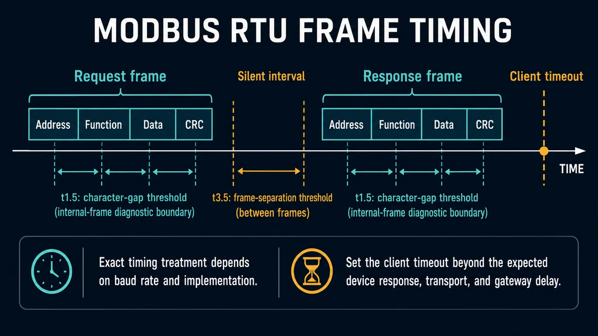
The client timeout must include expected server processing, serial transmission in both directions, configured response delay, gateway processing and downstream polling where applicable. It should not be used to hide broken framing. Measure representative and worst justified response time, then set a documented margin. If a response arrives consistently after the timer, identify why before increasing the value.
Keep retries from becoming the fault amplifier
Immediate retries can increase utilization precisely when the bus is congested or a gateway is slow. They may collide with a late response, exhaust gateway queues or obscure the first failure. Record the original attempt and distinguish retry responses with transaction identity and time. Use a bounded retry policy appropriate to process requirements, and avoid synchronized retry storms across multiple clients.
Calculate serial load from actual frame sizes, character format, baud rate, request rate, server delays and error/retry rate. An average utilization number can hide bursts. Observe the longest response time and queue behavior during the operating state that produces the fault.
Live mini-lab
Try it: press START, then STOP
A stop-dominant seal-in rung: START latches the motor output through its own contact, and STOP breaks the circuit.
Watch the output lamp: it stays on after START until you press STOP.
Free to start · runs in your browserOpens plcsimulationsoftware.com — same team
Interpret CRC, parity and incomplete-frame counters
Locate the receiver that rejected the frame
CRC is calculated by the receiver over the received RTU address and PDU bytes and compared with the transmitted CRC field. A mismatch proves the receiver did not accept the frame as intact; it does not by itself locate the disturbance. If the server rejects a bad request, the server's invalid/CRC counter may increase and the client may record only timeout. If the client rejects a bad response, the client's CRC counter increases. A gateway can maintain separate upstream and downstream counters.
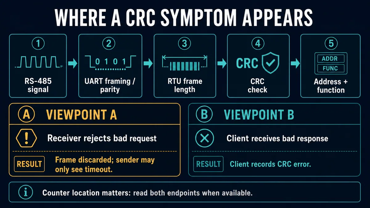
Reset counters only after preserving the original values and according to site procedure. Then run a small known number of transactions and compare deltas. A lifetime count of 500 says little without uptime and message volume; five errors in five controlled requests is decisive. Vendor diagnostic function 08 and product-specific pages may expose message, CRC, exception and no-response counts, but support and counter definitions vary.
Correlate errors with physical and operating conditions
When settings match, correlate counter increments with contactor or drive switching, machine motion, radio signal changes, particular nodes transmitting, high poll load, temperature or cabinet work. Inspect topology, reference/common arrangements, termination, bias/polarization, shielding, isolation and cable routing against the system drawings and manufacturer manuals. The detailed RS-485 wiring guide owns those physical-layer practices.
Do not change termination, swap A/B labels, join references or defeat isolation blindly. Vendor polarity naming is inconsistent, and live industrial networks can involve hazardous potential differences. Make de-energized checks and controlled substitutions under the electrical safety procedure and approved design.
| Counter pattern during controlled requests | Inference supported | Next isolating comparison |
|---|---|---|
| server received-message count unchanged | request did not reach/qualify at that server | client transmit, address/mode, path and server port state |
| server invalid/CRC count rises; client times out | server receiver rejected request before application reply | settings, request capture, collision/timing and physical quality |
| server sent-response rises; client receives nothing | response left server but was not accepted/returned to client | direction control, path, client receive counters and capture |
| client CRC count rises | client received an RTU frame that failed its CRC test | response direction, raw bytes, collisions and receiver quality |
| exception count rises | valid application exception returned | exact function/address/quantity and server state |
| timeout and retry counts rise with poll rate | load or response deadline may contribute | single-request baseline, response-time distribution and queue depth |
Diagnose Modbus TCP without inventing a CRC field
Separate connection, MBAP and PDU evidence
Modbus TCP carries an MBAP header followed by the Modbus PDU. The header contains Transaction Identifier, Protocol Identifier, Length and Unit Identifier fields. There is no RTU CRC field in the Modbus TCP application data unit. Ethernet frame checks and TCP/IP checksums belong to other layers and are handled by those stacks; a “Modbus CRC error” reported on a pure TCP endpoint must be traced to the product's terminology or a downstream serial path.
Begin with the configured endpoint: source and destination IP, routing/VLAN context, configured TCP port, connection establishment, reset/close events and retransmission or delay evidence. Port 502 is the registered/default Modbus TCP port in conventional implementations, but products and security architectures can use a configured alternative. Prove the active listener and client setting.
Then compare MBAP fields. The Protocol Identifier is normally zero for Modbus. The Length must match the following bytes defined by the protocol. The Transaction Identifier lets a client associate a response with a request, especially when more than one transaction is outstanding. The Unit Identifier is important when a TCP connection addresses devices behind a bridge; direct-server behavior and mapping are product-specific.
| TCP observation | Boundary supported | Decisive next check |
|---|---|---|
| no TCP connection establishes | IP route, listener, firewall, port or server capacity | connection trace at client and server plus listener/configuration evidence |
| connection establishes, no Modbus response | application request, server processing, gateway or correlation | MBAP/PDU capture and server request counter/log |
| connection resets under load | resource, idle/session policy or implementation issue | server connection limits, logs and controlled concurrency test |
| valid gateway exception | gateway received request and reported downstream/path condition | exception meaning and downstream serial counters |
| late response with unmatched Transaction ID | client correlation, reuse or queued old response | request-response timeline and outstanding transaction policy |
| TCP reply valid but values wrong | data-model interpretation | address, type, word order, scale and freshness |
Read a gateway from both sides
Document the upstream TCP timeout, gateway downstream response timeout, serial retry policy and total worst-case delay. If the gateway waits for multiple downstream attempts, the upstream client timer must not expire first unless the architecture intentionally accepts that behavior. Increasing the upstream timer alone can hide an unhealthy serial segment and lengthen failure detection.
Check the gateway mapping from Unit Identifier to serial address or route. Verify whether it serializes requests, how it handles multiple TCP clients, its queue limits, whether broadcasts are supported and what exception or connection behavior it uses for downstream silence. Use the exact gateway manual because these policies are not universal Modbus application behavior.
Capture traffic and find the first divergence
Compare one failing trace with a known-good trace
Use client logs, server diagnostics, managed-switch capture facilities, an approved network tap, gateway logs or an isolated serial analyzer appropriate to the system. A capture point only proves what crossed that point. A client-side TCP capture cannot prove that a downstream RTU server received the request. A serial monitor attached on one side of an isolator cannot automatically characterize the other side.
For each trace, annotate request start, complete frame, response start, response completion, client deadline and retry. Preserve raw bytes where policy permits. Record capture clock and dropped-packet indicators. Analyzer timestamps can reflect USB buffering or operating-system scheduling rather than exact wire timing; use suitable equipment when character-gap conclusions affect the diagnosis.
| Capture question | Evidence to preserve | Misinterpretation to avoid |
|---|---|---|
| did the request leave? | interface, direction, complete raw frame and timestamp | application “sent” log treated as wire transmission |
| did the peer receive it? | peer request/message counter or peer-side capture | client capture treated as peer evidence |
| was the frame acceptable? | length, parity/framing/CRC counters and raw bytes | timeout treated as proof of zero received bytes |
| did application processing occur? | exception/response counter, server log or valid reply | physical traffic treated as valid request processing |
| did the reply return in time? | response timestamp at each boundary and client deadline | any late reply treated as server silence |
| did the client correlate it? | address/function or MBAP Transaction ID match | received packet count treated as accepted response |
Change one variable and retain a rollback
Useful controlled comparisons include one client versus many, slow poll versus production poll, short documented register range versus the failing range, direct server connection versus approved gateway path, known-good adapter versus suspect adapter, and one isolated serial node versus the full segment. Change only one variable, preserve before/after evidence and restore the approved state after the test.
Avoid “shotgun” changes such as swapping cable, increasing timeout, changing parity and resetting the gateway together. A recovered link then yields no reusable cause and may hide a configuration discrepancy that will return.
Tune response deadlines, polling and recovery
Measure a response-time distribution
Collect response time under the normal and worst credible operating states, not only at an idle bench. Separate client scheduling delay, transport time, server processing, gateway queue/downstream time and reply transport where observability permits. Choose a timeout from the supported behavior and process requirement. The value must be long enough for valid responses but short enough for the application to detect loss within its required time.
Retries are not free reliability. Define which reads or idempotent operations may retry, how duplicate or late responses are rejected, how writes are handled, the delay/backoff, maximum attempts and what the application does after exhaustion. A write timeout is ambiguous: the server may have executed the write even though the client did not accept the reply. Verify actual state before automatically repeating a consequential command.
| Setting | Too aggressive | Too permissive | Evidence-led choice |
|---|---|---|---|
| response timeout | false timeouts and collision with late replies | slow fault recognition and occupied client resources | measured distribution plus justified margin |
| poll interval | saturation, queueing and retry amplification | stale application data | update requirement plus measured load |
| request quantity | more transactions and overhead | long frames, product limits and larger retry cost | coherent ranges within documented server limits |
| retry count | storm and duplicate ambiguity | transient loss becomes application failure | bounded policy based on consequence and link behavior |
| retry delay/backoff | repeated congestion at the same instant | unnecessarily slow recovery | desynchronized delay compatible with process need |
| concurrent transactions | server/gateway queue pressure and correlation defects | unused capacity where concurrency is supported | vendor limits plus controlled load test |
Define degraded-state behavior
The controller or application must distinguish fresh valid data, valid exception, timeout, bad quality, stale retained value and intentionally unavailable data. Do not present the last successful value as current after communications age exceeds the defined limit. Decide how control logic, operator displays, alarms, historian and higher-level systems behave during loss and recovery.
Communication loss is not automatically proof that the physical process is safe or unsafe. Fail behavior, fallback and recovery must come from the machine/process risk assessment and control requirements. Safety functions should not depend on an ordinary Modbus diagnostic guide or general-purpose client retry.
Commission and document the recovered link
Test more than a single successful poll
After correcting the demonstrated cause, repeat enough transactions to cover normal load, peak load, restart, reconnection and relevant operating modes. Confirm that error counters remain stable or within the documented acceptance criteria, response time stays inside the chosen deadline and data quality/age behaves correctly. Verify the exact request ranges and writes the production application uses.
| Commissioning case | Expected evidence | Acceptance question |
|---|---|---|
| normal read | matching valid response and fresh quality | does the application interpret address, type and scale correctly? |
| unsupported/invalid controlled request | documented exception where safe and supported | can client distinguish exception from timeout? |
| server unavailable simulation | bounded timeout/retry and explicit stale/bad state | does the application fail within its requirement? |
| restart/reconnect | predictable session and polling recovery | are old/late transactions rejected? |
| production load | response-time distribution and stable queues | does peak polling remain within capacity? |
| serial error-free run | stable CRC/parity/frame counters over defined message count | is the sample long and representative enough? |
| gateway downstream loss | documented upstream exception/timeout behavior | can technicians identify the failing side? |
| configuration backup/restore | versioned files and verified recovery | can the known-good state be reproduced? |
Close with a cause statement and prevention control
Write the cause at the deepest proven layer: “Server parity counter increased on every controlled request because client was Even and server was None,” not “Modbus problem.” Attach before/after configuration, counter deltas, captures, affected versions and rollback. Record why the change is correct and which test disproves the original symptom.
Prevention might be a configuration baseline, port label, automated communication-quality alarm, controlled timeout/load limit, gateway capacity rule, spare adapter qualification, clock-synchronized logs or a commissioning test. Update drawings and maintenance instructions through the site's change process.
Troubleshooting sequence by symptom
Use the shortest evidence path that preserves causality
| Symptom | First action | Second action | Likely decision boundary |
|---|---|---|---|
| every RTU device times out | verify client transmit and port mode/settings | check shared segment/gateway power and counters | client/shared path before individual server |
| one RTU device times out | compare its address/settings and server receive counter | compare branch/topology and peer device behavior | identity/device branch/server |
| CRC rises at server | capture repeated request and compare serial settings | correlate collisions/noise/topology under controlled load | request direction before application |
| CRC rises at client | capture response direction and server send count | compare adapter/segment and collision timing | response direction |
| valid exception returned | decode exception and preserve exact request | verify data map, function, state and permissions | application layer |
| TCP connection fails | verify endpoint, route, listener and port | inspect firewall/session/server logs | IP/TCP transport |
| TCP connects then times out | capture MBAP/PDU and server receive evidence | inspect gateway downstream and response time | application/gateway |
| fails only under load | reduce to one controlled request | measure queues, response distribution and retries | capacity/scheduling |
| values wrong but replies valid | verify protocol address, type, words and scale | compare raw registers with known process value | interpretation, not timeout |
Diagnostic answer map for Modbus timeout, CRC and no response
| Question a technician or AI assistant may ask | Short, extractable answer | Evidence that decides it |
|---|---|---|
| What does a Modbus timeout mean? | The client accepted no complete matching response before its configured deadline; it does not identify the cause. | client timer, raw request/response timeline and endpoint counters |
| Does a Modbus CRC error cause an exception response? | A receiver normally discards an RTU frame with invalid CRC, so the sender may see timeout rather than an exception. | receiving endpoint CRC/invalid counter and raw frame |
| Does Modbus TCP use CRC? | The Modbus TCP ADU uses an MBAP header and has no RTU CRC field; integrity mechanisms exist at Ethernet/TCP layers. | captured MBAP/PDU and transport documentation |
| Why does the client time out while the server shows CRC errors? | The server received but rejected damaged requests before application processing, so it did not return a Modbus reply. | server CRC counter delta matched to client requests |
| Is a Modbus exception a communications failure? | It is a valid Modbus response indicating the server parsed enough of the request to report an application condition. | exception function/code and matching request |
| Why can a gateway create longer timeouts? | It may queue the TCP request and wait through downstream serial response time and retries before replying upstream. | gateway policy, queue/serial counters and end-to-end timestamps |
| Should I increase the timeout? | Only after measuring valid worst-case response and proving the current deadline is the first divergence, not to conceal corruption or overload. | response-time distribution and error counters |
| Why does a broadcast write receive no reply? | Serial broadcast requests intentionally do not receive server responses. | address zero request and product support documentation |
Frequently asked questions
What causes a Modbus timeout?
A timeout can be caused by a request that never transmitted, wrong endpoint or address, mismatched serial settings, corrupted/discarded frames, missing route or TCP listener, firewall/session failure, server processing delay, gateway downstream failure, overload, an unmatched late response or a client deadline shorter than valid response time. The timeout itself does not select among them.
What causes a Modbus CRC error?
An RTU CRC mismatch means the bytes received do not match the transmitted CRC value. Causes can include corrupted, missing or extra bytes, collision, framing/timing problems, electrical integrity problems or incompatible mode/settings. Locate which receiver incremented the counter and compare raw frames and serial diagnostics before naming a component.
Will a Modbus device respond to a bad CRC request?
Normally no. The serial-line behavior is to discard a frame that fails its integrity checks, so the requester can see a timeout. A valid Modbus exception is different: it is a correctly formed response to a request the server parsed at the application layer.
What is the difference between Modbus timeout and no response?
“No response” describes the absence of an accepted reply; “timeout” describes the client timer event that declares the wait over. Some diagnostic products distinguish no bytes, partial data, CRC, connection and timeout categories, so preserve the exact status and raw evidence rather than treating every label as synonymous.
Does Modbus TCP have CRC errors?
The Modbus TCP application data unit does not contain the RTU CRC field. A pure TCP endpoint should be diagnosed through IP/TCP connection and MBAP/PDU evidence. A TCP-to-serial gateway may report CRC errors from its downstream RTU port, which can surface to the TCP client as a timeout or gateway exception.
How long should a Modbus timeout be?
Longer than the measured worst justified time for request transport, server processing, configured response delay, gateway queue/downstream transactions and reply transport, with a documented margin. It must also meet the application's failure-detection requirement. No one universal millisecond value fits every product and topology.
Can retrying fix Modbus communication errors?
A bounded retry can recover an occasional loss, but aggressive retries can increase congestion, collide with late serial responses and create duplicate-write ambiguity. Record the first failure, use transaction correlation, define backoff and maximum attempts, and verify actual state before repeating a consequential write.
Why does one Modbus register time out while others work?
First prove whether it truly times out or returns a valid exception. Compare function, starting protocol address, quantity, server range limits, access permissions and device state. A successful request to the same endpoint is a strong transport control; address notation and invalid range are then more likely than a shared cable fault.
How do I test a Modbus CRC fault?
Preserve counter baselines, send a known small number of identical approved requests and compare client, server and gateway counter deltas. Capture raw bytes and timing at the relevant receiver where possible. Change one setting or path variable at a time, then repeat the same request and retain rollback evidence.
What should be logged for an intermittent Modbus no-response fault?
Log exact request identity, client timeout/retry state, send and response timestamps, raw result class, TCP session or serial framing status, CRC/parity/incomplete-frame counters at each endpoint, gateway downstream state, message volume, configuration versions and relevant machine/network conditions. Use a synchronized time reference and state what was observed versus inferred.
Sources, review scope, and limitations
This guide synthesizes protocol and product-diagnostic evidence from the primary sources below. Exact timing, port mode, counters, gateway mapping, server capacity and failure behavior are implementation-specific. The installed manuals, approved architecture, electrical design, cybersecurity controls, risk assessment and change procedure take precedence.
- Modbus Organization: Modbus Specifications and Implementation Guides — official index for the application protocol, serial-line and TCP messaging documents.
- Modbus over Serial Line Specification and Implementation Guide V1.02 — master/slave behavior, RTU and ASCII framing, CRC/LRC, address/broadcast handling, timing and two-wire RS-485 guidance.
- Modbus Application Protocol Specification V1.1b3 — request/response PDUs, function codes, data addressing and exception responses.
- Modbus Messaging on TCP/IP Implementation Guide V1.0b — MBAP header, client/server transaction model and TCP connection management.
- Siemens 3WT Circuit Breakers with Modbus TCP/RTU System Manual — explicit distinction among valid replies, discarded communication-invalid requests, no response/timeout and logical exception responses.
- Siemens SITRANS F Modbus RTU Instructions — communication status, CRC/parity/frame counters, interframe configuration and response timing examples.
- Siemens Modbus RTU Communication Manual — serial settings, parity/CRC discard behavior, exceptions and timeout/response-time configuration.
- Siemens SIPROTEC Modbus Communication Profile — framing, parity, CRC and response-time counters plus function 08 diagnostic examples.
- Schneider Electric Power Monitoring Expert Diagnostics Viewer — timeout, bad CRC, incomplete frame, broken connection, response time, utilization and request/error ratio definitions.
- Schneider Electric Modbus Serial IOScanner Configuration — response timeout, inter-frame time, RTU CRC versus ASCII LRC and common line settings.
- Schneider Electric TM3 Bus Coupler Diagnostics — messages sent/received/invalid and timeout/corrupt-message diagnostic counters.
- Schneider Electric Serial Line Configuration — serial mode, baud, parity, data/stop bits, RS-485 polarization and protocol-selection considerations.
- Schneider Electric Modbus Manager — Modbus Manager timing and function 08 communication-diagnostic configuration.
Now run it · free to start
Learn Modbus, then the networks around it
Modbus first because it is simple and everywhere, then the Ethernet-based protocols and the SCADA layer above them. Free to start.
Ownership disclosure: PLC Programming IO and PLC Simulation Software are operated by the same publisher.
PLC Programming IO Editorial Team
Industrial automation education, references, and software testing
The PLC Programming IO Editorial Team publishes sourced industrial-automation education and documents how material is reviewed, tested, and corrected. A team byline means the publisher is responsible for the page; it does not represent a fictional person or imply an engineering licence.
Coverage:
- • PLC programming concepts and examples
- • Vendor software tutorials and comparisons
- • SCADA, HMI, protocols, and instrumentation
- • Training, careers, and reference material
Review standard:
- • Prefer primary and official sources
- • Record software versions when material
- • Separate tested facts from estimates
- • Publish material corrections
Important scope note
This site provides education, not project-specific engineering approval. Safety, code, and compliance decisions require a qualified person with access to the actual machine and jurisdiction.