RS-485 Wiring: Termination, Biasing, Grounding and Diagnosis
Wire and troubleshoot two-wire or four-wire RS-485 by proving polarity, topology, end termination, idle bias, signal reference, shielding and protocol settings one layer at a time.
Review status: Editorially reviewed against cited standards-organization and manufacturer guidance; device terminal definitions and electrical limits require installed-manual verification
Direct answer
Wire RS-485 as the exact physical layer required by the installed devices: confirm two-wire half-duplex or four-wire full-duplex, map each manufacturer’s terminal names to actual signal polarity, run a shielded twisted-pair trunk instead of a star, terminate only the physical ends when the device documentation requires it, and provide fail-safe bias at one intentional location unless the documented transceivers already guarantee the idle state. Treat signal reference, cable shield and protective earth as different conductors. Commission the physical layer before debugging baud rate, parity, addressing or Modbus registers.
Do not connect solely by matching the letters A and B. Vendors do not use those letters consistently. One product may equate A with negative/inverting while another uses A for positive/non-inverting. Match the manual’s D0/D1, minus/plus or inverting/non-inverting definition, verify the connector pinout, and document the mapping at both ends. A polarity swap usually produces silence, but intermittent replies can also result from topology, termination, bias, common-mode or turnaround timing.
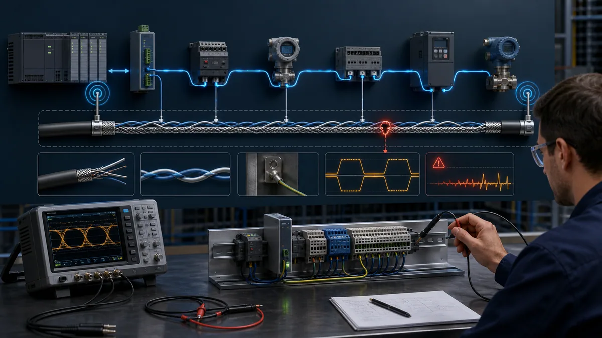
What RS-485 defines and what it does not
RS-485 is an electrical signalling standard for differential multipoint communication. It describes transmitter and receiver electrical behaviour; it does not define the message meaning, device address, register model, retry strategy or commissioning screen. Modbus RTU, BACnet MS/TP, proprietary drive protocols and other systems can use an RS-485 physical layer while requiring different protocol configuration and bias/termination conventions.
Keep the diagnostic layers separate
A healthy RS-485 waveform can carry frames that the target rejects because of the wrong address, parity, function or timing. Conversely, perfect protocol configuration cannot compensate for reversed polarity, a broken reference conductor or a star topology that rings at the chosen edge rate. Diagnose in this order: installation identity, electrical topology, idle state and waveform, serial format, frame validity, target address and application data.
| Layer | Question to prove | Typical evidence |
|---|---|---|
| Device identity | Are these the exact ports, firmware and interface options expected? | catalogue number, option code, connector drawing, firmware, port mode |
| Physical mode | Is the link two-wire or four-wire, and is transmit control internal or configured? | device manual, terminal count, port configuration |
| Conductors | Are pair, reference and shield mapped correctly end to end? | cable schedule, continuity under isolation, connector pinout |
| Topology | Is there one trunk with controlled stubs and two physical ends? | as-built route and node-order drawing |
| Termination and bias | Are only the required networks enabled at the documented locations? | switch/jumper inventory, power-off inspection, waveform |
| Serial format | Do baud, data bits, parity and stop bits match? | configuration export and captured frames |
| Protocol | Is the role, address and request valid for the device? | client/server configuration, frame decode, device manual |
| Application | Is the requested object/register and data interpretation correct? | protocol specification, register map, raw response |
For a short definition and conceptual overview, use What Is RS-485?. This page is the canonical installation and fault-finding owner.
Two-wire and four-wire RS-485
The phrase “two-wire RS-485” normally means one differential pair is shared for transmit and receive in half-duplex. Only one driver may control the bus at a time, so a controller, gateway or transceiver must enable and release its driver at the correct moment. “Four-wire RS-485” normally uses one pair in each direction. It can support simultaneous transmission, but many industrial master/client arrangements still behave as request-response systems.
Count functional conductors, not every copper path
Two-wire and four-wire naming counts signal-pair conductors. An installation may also require a signal-reference/common conductor and a shield, so a “two-wire” cable connection can involve more than two terminals. The shield is not automatically a valid signal reference, and protective earth is not automatically interchangeable with either.
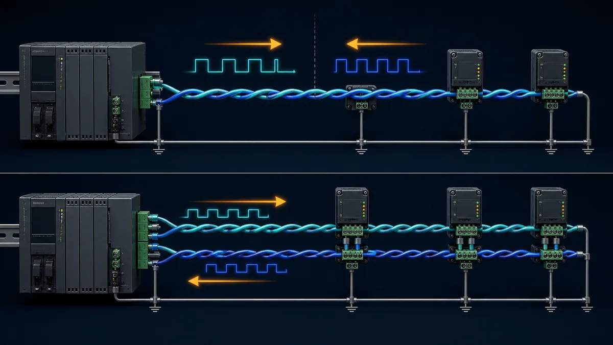
| Property | Two-wire half-duplex | Four-wire full-duplex |
|---|---|---|
| Signal pairs | one shared pair | separate transmit and receive pairs |
| Driver control | critical because multiple drivers share one pair | each direction has a defined driver arrangement |
| Common industrial use | multipoint request-response networks | master-to-many receive path plus return path, or special point-to-point links |
| Common wiring mistake | both sides drive simultaneously or driver releases too late | transmit pair connected to transmit pair instead of the opposite receiver pair |
| Termination concept | each physical end of the shared trunk | receiver end of each directional line according to device guidance |
| Conversion risk | “automatic” direction control timing may not suit all frame gaps | device roles and pair naming can be misunderstood |
Do not assume a four-terminal connector proves four-wire operation. Terminals may include a reference, shield or internal termination point. Confirm the manual and configured port mode.
Decode A, B, plus, minus, D0 and D1 safely
Terminal naming is one of the most common sources of failed RS-485 commissioning. The letters A and B alone are insufficient because vendor conventions differ. A reliable cable schedule records each device’s terminal label, connector pin, described polarity/function and mapped network conductor.
Build a translation table before landing wires
Choose neutral project names such as DATA_0 and DATA_1, then map each product from its manual. If the protocol implementation guide defines D0 and D1, retain those names in the network drawing and show each device’s vendor alias. When a manual supplies only A/B without electrical definition, use an approved test or manufacturer support rather than guessing from colour or another product.
| Device | Physical terminal | Manual’s electrical description | Project conductor | Verified by |
|---|---|---|---|---|
| PLC serial module | record exact label/pin | D0/D1, minus/plus or inverting/non-inverting | DATA_0 or DATA_1 | manual section and revision |
| Gateway/converter | record exact label/pin | transmit/receive function and port mode | DATA_0 or DATA_1 | manual plus configuration export |
| Drive/instrument | record exact label/pin | protocol-specific polarity notation | DATA_0 or DATA_1 | device operating instructions |
| Repeater/isolator | record both-side labels | side A/side B direction and isolation boundary | segment-specific pair | installation manual |
Cable colours are a project convention, not an RS-485 definition. Preserve pair integrity and use the same documented colour mapping throughout the segment.
Use one trunk, two ends and controlled stubs
The preferred multipoint geometry is a linear bus or daisy chain: the twisted pair enters and leaves each node so the cable has two physical ends. Long branches and star centres create impedance discontinuities. Signal energy can travel down a branch, reflect and return during a receiver’s decision window.
“Daisy chain” describes the cable path
It does not require current to pass through powered electronics at every node. Suitable terminals or connectors can continue the trunk while presenting a short local connection to the transceiver. A removable connector that breaks the onward pair when unplugged may still make downstream nodes dependent on it, so document connector behaviour and maintenance implications.
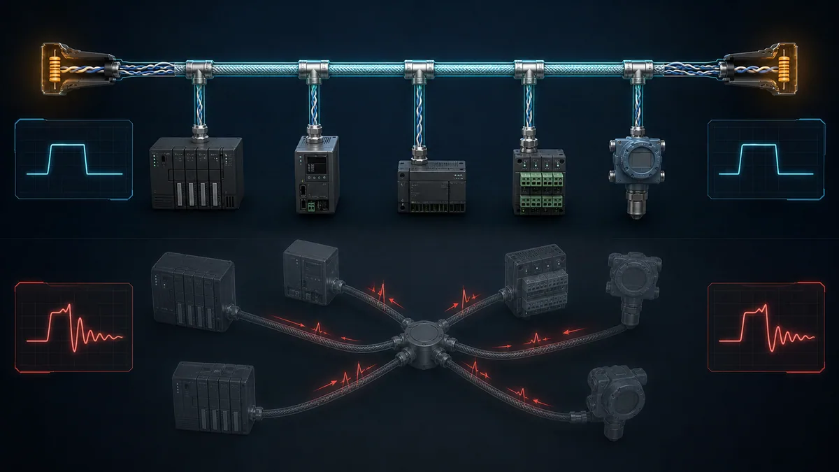
| Topology finding | Likely consequence | Corrective decision |
|---|---|---|
| one continuous trunk with two ends | easiest termination and waveform control | document node order and end devices |
| long T branches | reflections that worsen with edge rate and branch length | reroute trunk or use an approved active repeater/segment design |
| passive star junction | several electrical ends and complex reflections | redesign; do not add termination to every branch by intuition |
| spur to a panel-mounted device | may be acceptable only within device/cable guidance | measure the physical spur and compare with manufacturer limit |
| repeater between segments | each segment becomes its own electrical bus | terminate/bias each side according to repeater and device manuals |
The Analog Devices AN-960 guide relates stub length to signal wavelength and edge behaviour. A simple universal “maximum stub length” is unreliable because cable velocity, driver rise time, data rate and receiver behaviour all matter. Use the most restrictive installed-device guidance and validate the waveform when the design approaches a limit.
Terminate the actual transmission-line ends
Parallel termination places a resistance approximately matching the cable’s differential characteristic impedance across the pair at the appropriate physical ends. In a common two-wire bus using nominal 120-ohm cable and device guidance, that often means one termination at each end—not one resistor per device and not automatically one at the logical master plus another at an arbitrary “last address.”
Locate the ends physically
Trace the cable. The master can sit in the middle of a trunk; in that case it is not a physical end. A repeater divides the network into electrical segments, each with its own ends. Some devices switch an internal termination, some require an external resistor, and some include a combined termination/polarisation network. Record every enabled network, including converters and temporary service adapters.
The TI termination guidance explains that the familiar 120-ohm value comes from the differential characteristic impedance of common twisted-pair bus cable. The value is not a decoration: a different specified cable or integrated network requires its documented design value.
| Termination mistake | Observable effect | Evidence |
|---|---|---|
| no termination on a long/fast segment | ringing, multiple threshold crossings or distance-sensitive errors | end-of-line waveform and device error rate |
| termination at every node | excessive loading and reduced differential amplitude | power-off inventory, equivalent resistance, driven waveform |
| three or more ends on a passive star | reflections plus excessive load if every end is terminated | as-built topology and waveforms at multiple branches |
| termination powered by a device that is switched off | segment changes behaviour with that node’s power state | termination design, node power state and idle waveform |
| wrong resistor or wrong terminals | incomplete matching or direct bias/reference disturbance | component value, pin mapping and manual |
With power removed and every device in the documented safe state, two 120-ohm end resistors appear as about 60 ohms in ideal parallel. Real networks contain bias networks, transceiver input paths, protection and meters, so a resistance reading is only supporting evidence. Do not disconnect or ohm-test an energized bus, and do not infer the exact design from one reading.
Live mini-lab
Try it: press START, then STOP
A stop-dominant seal-in rung: START latches the motor output through its own contact, and STOP breaks the circuit.
Watch the output lamp: it stays on after START until you press STOP.
Free to start · runs in your browserOpens plcsimulationsoftware.com — same team
Provide one intentional idle-state or fail-safe strategy
On a half-duplex bus there are intervals when no driver actively drives the pair. Legacy receivers may have an undefined output around zero differential voltage. A fail-safe bias network establishes a known idle state. Many modern transceivers include open/short/idle fail-safe behaviour, but a mixed installed network must be evaluated from the exact device data sheets.
Avoid fighting bias networks
External pull-up and pull-down resistors are normally implemented at one intentional location for the segment, often with the controller or active termination network. Enabling bias at several devices changes common-mode and differential loading. The correct values depend on supply tolerance, termination, transceiver thresholds, unit loading and the specified noise margin; do not copy resistor values from a different network without calculation and device approval.
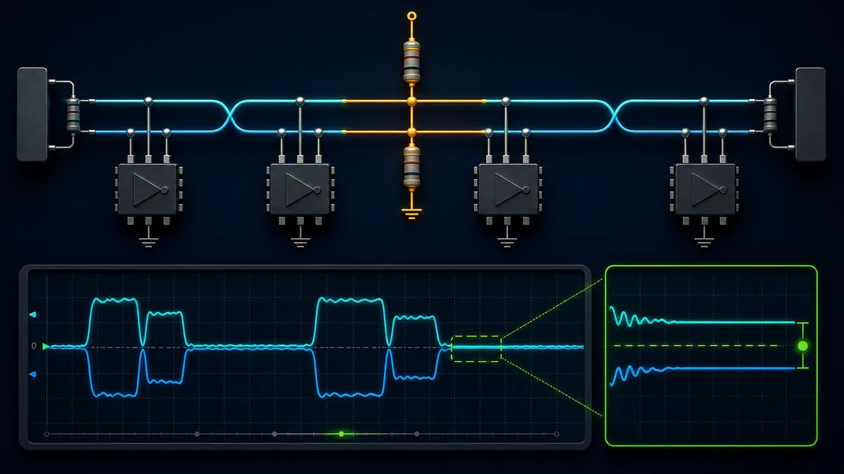
| Idle-state observation | Candidate cause | Next check |
|---|---|---|
| random receive characters while no station transmits | undefined/floating idle, noise or wrong receiver mode | inventory internal/external fail-safe features and observe idle differential state |
| good communication only when one device is powered | that device may supply bias or active termination | inspect its network and test an approved independent segment design |
| low driven amplitude after adding a gateway | duplicate bias/termination or excess unit loading | inventory every enabled resistor and transceiver load |
| correct idle level but frames fail | polarity, waveform, serial format or turnaround—not idle bias alone | capture a request and response at both ends |
TI’s fail-safe guidance shows both integrated receiver behaviour and external bias approaches. The Modbus Serial Line implementation guide also defines a line-polarisation convention for that ecosystem. Apply the protocol and device rules for the actual network rather than mixing recommendations from unrelated implementations.
Separate reference, shield, bonding and protective earth
Differential signalling rejects some common noise, but every receiver has a finite common-mode operating range. Long runs, separate power systems and high current equipment can create ground-potential differences. A documented signal-reference conductor can help keep device common-mode voltage within limits; it is not the same thing as using the cable shield as an uncontrolled current return.
Treat shielding as an EMC design decision
Shield termination depends on frequency, cable, enclosure, device port, bonding system and site EMC design. A one-end rule copied from an analog instrumentation loop is not a universal RS-485 rule. Follow the device and system manual, preserve the shield through connectors as specified, maintain pair twist near the terminal and bond cabinet entries using the approved method.
When expected potential difference or transient environment exceeds interface capability, galvanic isolation, surge protection, fibre conversion or an isolated repeater may be required. Isolation must include the necessary signal and power boundary, and it does not excuse poor topology or termination.
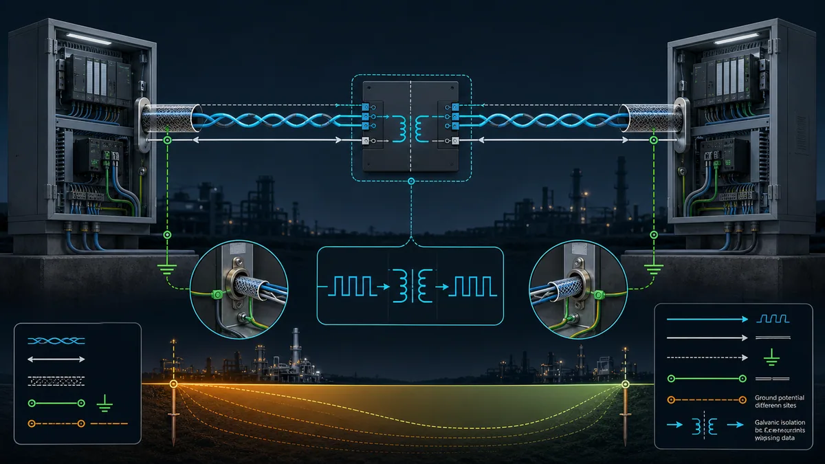
| Conductor or boundary | Primary purpose | Common error |
|---|---|---|
| differential twisted pair | carries opposing signal voltages | splitting conductors across different pairs or untwisting excessively |
| signal reference/common | controls receiver common-mode relationship where specified | omitting it or bonding it arbitrarily to noisy current paths |
| cable shield | intercepts/couples high-frequency interference according to EMC design | using it as the only signal return without approval |
| protective earth/bonding | personnel safety and equipotential bonding per electrical design | treating it as interchangeable with circuit common |
| galvanic isolation | passes information while interrupting direct current path | isolating signals but leaving an unintended power/reference path |
Select cable, length and speed as a system
Use cable specified for RS-485 or the installed vendor network: controlled differential impedance, twisted pair, suitable capacitance, conductor size, shielding and environmental rating. Building, tray, flex, oil, UV, temperature and hazardous-location requirements can be as important as the nominal impedance.
Avoid a single universal distance claim
Maximum useful length depends on data rate, cable loss/capacitance, driver edge rate, topology, termination, transceiver thresholds, node loading, isolation components and noise. Analog Devices illustrates the general trade-off: higher data rate permits shorter cable, while low-rate distance is limited by DC and noise considerations. Published headline combinations are examples, not guaranteed design points for every PLC network.
| Design variable | If increased | What must be rechecked |
|---|---|---|
| cable length | attenuation, delay and resistance grow | data rate, termination, common-mode, conductor size and waveform |
| data rate or edge speed | reflections occupy more of the bit interval | topology, stubs, cable and termination |
| number of nodes | unit loading and connection complexity grow | transceiver unit-load ratings, bias, amplitude and power distribution |
| stub length | reflection path grows | receiver waveform at the operating edge rate |
| environmental exposure | insulation, shield and connection risks grow | cable rating, gland, bonding, surge and maintenance design |
Count unit loads from transceiver specifications, not merely physical devices. Modern fractional-unit-load receivers can permit more nodes electrically, but protocol addressing, repeaters, power, response timing and vendor limits may impose a lower system limit.
Commission the bus in a controlled order
Commissioning is faster when each step establishes one layer before the next. Start with an isolated inspection, then energize under the approved procedure and observe idle and driven states before polling the whole plant.
Use a minimum viable segment
Begin with one client/master and one server/slave on a short documented segment when practical. Confirm interface mode, polarity, serial format, address and a known supported request. Add trunk length and nodes incrementally while watching response quality. This distinguishes a global configuration error from a loading, topology or node-specific problem.
| Commissioning step | Pass evidence | Stop condition |
|---|---|---|
| identity and drawings | every port, option, pin and conductor mapped | ambiguous A/B or undocumented converter mode |
| isolated physical inspection | trunk, stubs, shield, reference, termination and bias match design | star branch, damaged cable, unsafe or unknown termination |
| idle energization | stable documented idle state; no unexpected driver | contention, overheating, incorrect common-mode or random characters |
| single-node exchange | valid request and valid response at correct address | no frame, framing errors or unexpected transmitter overlap |
| incremental nodes | each addition preserves amplitude, timing and valid frames | error begins after one node/segment addition |
| full operating test | worst-case operating state meets error and response criteria | errors correlate with motor switching, node power or loading |
For Modbus frame structure and register behaviour after the physical layer works, use the Modbus RTU protocol tutorial.
Diagnose no-response and intermittent errors
Divide the symptom by direction and layer. First determine whether the client request is physically present at the far device. Then determine whether the server responds at its terminals. Finally determine whether the response survives the return path and whether the client accepts it.
Capture at more than one point
A serial analyser or differential oscilloscope used by a qualified person can show polarity, amplitude, ringing, idle state, contention and timing. The instrument connection changes the circuit, so use suitable differential/isolation methods and rated probes. Never connect a grounded bench oscilloscope blindly to an industrial circuit.
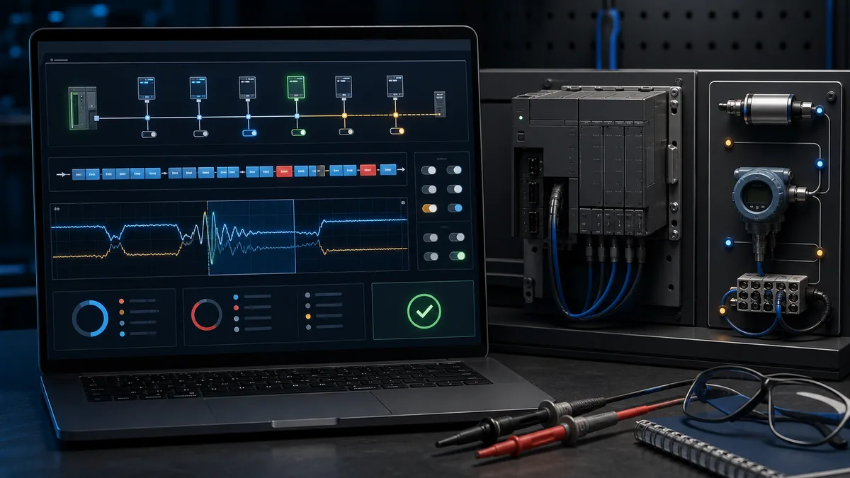
| Symptom | First physical check | Then configuration/protocol check |
|---|---|---|
| no device responds | interface mode, polarity, reference, client waveform and trunk continuity | port selection, baud/parity and client driver control |
| one device does not respond | request at that node, connector/drop and its power | unique address, server role and supported function |
| replies fail only at distant nodes | end waveform, termination, cable/stubs and common-mode | response timeout after physical quality is proven |
| random framing or CRC errors | idle stability, ringing, contention, interference and reference | baud/parity mismatch or converter turnaround |
| works with one node but not many | duplicate termination/bias, loading and topology | duplicate addresses and polling load |
| works until end device loses power | active termination or bias powered by that node | power architecture and documented independent termination |
Read waveforms comparatively
Do not diagnose from a generic ideal screenshot alone. Compare a known-good location with the failing end under the same request and operating condition. Record probe method, time scale, vertical scale, location, reference and network state. Excess ringing, slow edges, low differential amplitude, unstable idle or overlapping drivers each points to a different next test.
| Waveform feature | Possible interpretation | Confirmation |
|---|---|---|
| repeated threshold crossings after an edge | reflection from termination, branch or impedance discontinuity | compare both ends and change one documented topology variable |
| low amplitude across entire segment | excessive loading, too many terminators or driver/cable issue | termination inventory and segment-by-segment comparison |
| valid request, no response drive | target not receiving/accepting or driver not enabled | capture at target pins and inspect target diagnostics/configuration |
| two drivers overlap | turnaround/direction control or duplicate-master contention | correlate transmit-enable timing and roles |
| idle wanders near decision threshold | missing/weak bias, interference or reference problem | inventory fail-safe design and observe with transmitters released |
Prove the repair and preserve the as-built network
A repaired bus should pass the same worst-case condition that exposed the error: full node count, longest path, normal motor/drive switching, expected device power states and production polling load. Verify more than successful replies; confirm error counters remain stable, response times remain within the application limit and waveforms retain margin at the furthest nodes.
Close with an acceptance record
Record node order, cable and segment lengths, stub lengths, termination and bias locations, device/firmware identities, port settings, shield/reference design, repeater boundaries, baseline waveform captures and protocol test results. Label both physical ends. A future technician should not need to rediscover which device secretly supplies the only active termination.
| Acceptance item | Required result |
|---|---|
| Physical inventory | as-built drawing matches every node, segment, repeater, end and conductor mapping |
| Termination/bias | enabled locations and networks match the approved calculation/device guidance |
| Electrical evidence | idle and driven waveforms are stable at representative near/far points |
| Protocol evidence | valid exchanges occur for every address under expected polling load |
| Disturbance test | normal switching and environmental conditions do not create new errors |
| Restoration | temporary analysers, jumpers and test settings removed; covers and safeguards restored |
| Baseline | configuration export, counters and captures retained with date and time basis |
Diagnostic answer map for search and AI-assisted troubleshooting
The following natural-language queries route to one canonical answer surface instead of separate keyword-swapped pages.
| Expanded query | Direct answer surface |
|---|---|
| How do I wire a two-wire RS-485 PLC network? | use one shared twisted pair as a trunk, map device polarity from each manual, include the documented reference/shield paths and terminate/bias only at designed locations |
| Is RS-485 A positive or negative? | A/B is vendor-inconsistent; translate from the manual’s D0/D1, plus/minus or inverting/non-inverting definition |
| Where do RS-485 termination resistors go? | at the physical electrical ends required by the segment/device design, not at every node or simply at the lowest/highest address |
| Does every RS-485 device need a 120-ohm resistor? | no; parallel end termination commonly produces two terminations on one segment, while device/cable designs can differ |
| Where should RS-485 bias resistors be installed? | at one intentional segment location unless the documented receivers or active termination provide the required idle fail-safe state |
| Should RS-485 shield be grounded at one end or both? | there is no universal rule; follow the system EMC, bonding and device guidance for the cable and installation |
| Does RS-485 need a ground wire? | differential signalling still has common-mode limits; use the documented reference/common path or isolation strategy rather than assuming shield or protective earth is equivalent |
| Why does RS-485 work with one device but fail with several? | inventory duplicate bias/termination, node loading, topology/stubs, addresses and power-dependent active networks |
| Why does Modbus RTU work close up but fail over the installed cable? | compare far-end waveform, polarity, termination, cable, stubs, reference/common-mode and interference before increasing timeouts |
| How can I test RS-485 without guessing? | prove request at the client, request at the target, response at the target and response at the client with time-aligned physical and decoded evidence |
Frequently asked questions
Can I connect RS-485 A to A and B to B?
Only after confirming both manuals use the same convention. A/B notation is inconsistent across products. Map each terminal to D0/D1, minus/plus or inverting/non-inverting as defined by its manufacturer. If communication is silent, do not repeatedly swap wires on energized equipment; isolate as required, verify the pinout and update the cable schedule.
How many wires are needed for two-wire RS-485?
The “two” refers to the differential signal pair. The installation may also require a signal-reference/common conductor and a shield, with protective bonding handled separately. Follow the device and system installation manuals. Do not use the shield automatically as the circuit reference.
Where should the RS-485 termination resistor be installed?
Install termination at the electrical ends specified for the segment and devices. A common half-duplex trunk has one parallel termination at each physical end. The logical master is not necessarily an end, and a repeater creates new segments. Record internal switches, external resistors and active termination networks.
Why does adding more termination make RS-485 worse?
Every parallel termination loads the driver. Adding a resistor at each node can reduce differential amplitude and exceed the designed load. More resistors do not “absorb more noise.” First map the physical ends, cable impedance and integrated networks, then compare the waveform with the approved design.
What is RS-485 fail-safe biasing?
It is a method for giving an undriven bus a known idle differential state. It can be provided by suitable receiver behaviour or an external pull-up/pull-down network. External bias is normally coordinated at one segment location. Values must be calculated with termination, thresholds, supply tolerance and node loading.
Should the RS-485 cable shield be connected at both ends?
It depends on the documented EMC and bonding design, cable, device ports and installation. One-end and multi-point strategies solve different coupling problems. Follow the most specific system/device instructions and site electrical design; do not create an undocumented shield or ground-current path during troubleshooting.
Why does RS-485 communication fail when a distant device is powered off?
That device may supply an active termination or the only bias network, its connector may interrupt the onward trunk, or the segment’s reference/common-mode state may change. Inspect the connector and termination design, compare idle and driven waveforms, and redesign so required network functions remain available under intended power states.
How long can an RS-485 cable be?
There is no single guaranteed distance. Cable, data rate, driver edge rate, topology, stubs, termination, loading, common-mode environment and vendor limits interact. Use the most restrictive installed-device and cable guidance, then validate at the actual node count and operating conditions.
Can Ethernet cable be used for RS-485?
Only if its electrical and environmental characteristics satisfy the installed-device and system requirements. Pair integrity and characteristic impedance may be suitable in some controlled applications, but shielding, capacitance, conductor size, flex/oil/temperature rating and connector practice may not be. Approval cannot be based on the connector or pair count alone.
What should I test first when Modbus RTU has no response?
Confirm the exact serial port and two-/four-wire mode, then verify polarity and that a request waveform reaches the target. If the target sees a valid request, check baud, parity, stop bits, address and function support. If it transmits a response, follow that response back through the physical path before changing timeouts or register addresses.
Sources, review scope, and limitations
Direct sources reviewed
- Analog Devices AN-960 — RS-485/RS-422 Circuit Implementation Guide, accessed 2026-08-28. Used for half-/full-duplex concepts, termination, stubs, data-rate/length trade-offs, fail-safe bias and isolation context.
- Texas Instruments — When Termination Is Necessary and How to Do It Properly, revised March 2026, accessed 2026-08-28. Used for characteristic-impedance and parallel-termination context.
- Texas Instruments — Two Ways to Fail-safe Bias Your Network, accessed 2026-08-28. Used for integrated and external fail-safe design context.
- Modbus Organization — Modbus Serial Line Protocol and Implementation Guide V1.02, accessed 2026-08-28. Used for Modbus-over-RS-485 topology, D0/D1 naming, line polarisation and serial implementation context.
- Siemens SINAMICS V20 Operating Instructions, December 2024, accessed 2026-08-28. Used as a current device-specific example of shielded twisted-pair and termination-network requirements; values are not generalised to other devices.
- Rockwell Automation PowerMonitor 500 Unit User Manual, 1420-UM001G-EN-P, accessed 2026-08-28. Used as an example of product-specific A-/B+ naming and internal termination activation.
- Phoenix Contact EMpro Modbus/RTU documentation, revision dated 2025-07-15, accessed 2026-08-28. Used as an example of device-specific pair, shield, termination, bias and serial-parameter requirements.
- OSHA 29 CFR 1910.147 — The control of hazardous energy, accessed 2026-08-28. Used for the United States hazardous-energy-control boundary during covered servicing and maintenance.
Scope and limitations
This guide is vendor-neutral installation and diagnostic education. It is not an approved wiring diagram, intrinsic-safety design, surge/lightning design, hazardous-location assessment, live-measurement method or substitute for the TIA/EIA-485 standard and installed-device manuals. Terminal names, pin numbers, termination values, bias values, common-mode limits, node limits and shield/reference connections are product- and system-specific.
The generated figures explain relationships but are not construction drawings. Browser simulation can help practise topology, termination, bias, direction timing and frame diagnosis, but it cannot reproduce a cable’s actual impedance, site ground potential, EMC environment or transceiver protection. Qualified personnel must approve wiring changes, energized measurements and commissioning acceptance.
Now run it · free to start
Follow plant data from sensor to SCADA
Fieldbus versus Ethernet, Modbus, EtherNet/IP, PROFINET, OPC UA and MQTT, then SCADA layers and alarms, taught on simulated equipment. Free to start.
Ownership disclosure: PLC Programming IO and PLC Simulation Software are operated by the same publisher.
PLC Programming IO Editorial Team
Industrial automation education, references, and software testing
The PLC Programming IO Editorial Team publishes sourced industrial-automation education and documents how material is reviewed, tested, and corrected. A team byline means the publisher is responsible for the page; it does not represent a fictional person or imply an engineering licence.
Coverage:
- • PLC programming concepts and examples
- • Vendor software tutorials and comparisons
- • SCADA, HMI, protocols, and instrumentation
- • Training, careers, and reference material
Review standard:
- • Prefer primary and official sources
- • Record software versions when material
- • Separate tested facts from estimates
- • Publish material corrections
Important scope note
This site provides education, not project-specific engineering approval. Safety, code, and compliance decisions require a qualified person with access to the actual machine and jurisdiction.