Modbus Function Codes and Exception Codes: Practical Reference
Choose the correct Modbus function, decode normal and exception responses, separate protocol exceptions from timeouts, and diagnose address, value and gateway faults safely.
Review status: Editorially reviewed against the Modbus Organization application and serial-line specifications plus cited manufacturer documentation; installed-device support and register maps require model-specific verification
Direct answer
A Modbus function code tells a server what operation the client requests. The most common public codes are 01 read coils, 02 read discrete inputs, 03 read holding registers, 04 read input registers, 05 write one coil, 06 write one holding register, 15 (0F hex) write multiple coils and 16 (10 hex) write multiple holding registers. A normal response begins with the requested function code. A protocol exception response returns that function with its most-significant bit set—equivalent to adding hexadecimal 0x80—followed by a one-byte exception code. A request using function 03, for example, produces exception function 83 hex when the server understood the frame but rejected or could not complete the operation.
Do not call every failed Modbus transaction an exception. A genuine exception is a valid response from a server. Silence, a TCP connection failure, a CRC error discarded by the receiver, or a client-side timeout has no Modbus exception PDU. Diagnose those transport and physical-layer results separately. Also separate a protocol exception byte from a client library's local status number: software vendors frequently use their own codes for timeout, socket, parsing and configuration failures.

Function-code quick reference
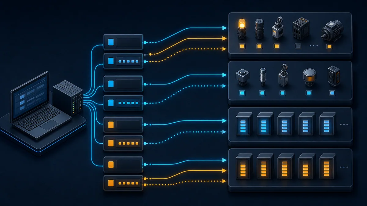
The function selects both an operation and a Modbus data model area. It is not merely a read/write flag. Function 03 reads holding registers; function 04 reads input registers. Even if two vendor documents print similar-looking register numbers, swapping those functions can yield different data or an exception because the logical tables are different.
Core bit and register functions
The table below uses decimal and hexadecimal notation together because configuration tools, packet decoders and manuals vary. Decimal 16 and hexadecimal 0x10 are the same function. Decimal 10 and hexadecimal 0x0A are not.
| Decimal | Hex | Standard function name | Typical data area | Request carries | Successful response carries |
|---|---|---|---|---|---|
| 1 | 0x01 | Read Coils | read/write single-bit outputs | start address and quantity | byte count and packed bit states |
| 2 | 0x02 | Read Discrete Inputs | read-only single-bit inputs | start address and quantity | byte count and packed bit states |
| 3 | 0x03 | Read Holding Registers | read/write 16-bit registers | start address and quantity | byte count and register words |
| 4 | 0x04 | Read Input Registers | read-only 16-bit registers | start address and quantity | byte count and register words |
| 5 | 0x05 | Write Single Coil | one coil | output address and encoded ON/OFF value | echo of address and value |
| 6 | 0x06 | Write Single Register | one holding register | register address and 16-bit value | echo of address and value |
| 15 | 0x0F | Write Multiple Coils | contiguous coils | start, quantity, byte count and packed values | start address and quantity written |
| 16 | 0x10 | Write Multiple Registers | contiguous holding registers | start, quantity, byte count and words | start address and quantity written |
A public function can still be unsupported by an individual product. The authoritative capability list is the installed device's current communication manual and firmware documentation, not the fact that a code exists in the Modbus specification.
Less-common public and diagnostic functions
| Decimal | Hex | Function | Practical use | Important qualification |
|---|---|---|---|---|
| 7 | 0x07 | Read Exception Status | legacy status-byte access | serial-line function; device support varies |
| 8 | 0x08 | Diagnostics | serial link testing and counters | subfunction meaning matters; not a generic TCP health request |
| 11 | 0x0B | Get Comm Event Counter | communication event count | serial-line context |
| 12 | 0x0C | Get Comm Event Log | event and message counters | serial-line context and implementation limits |
| 17 | 0x11 | Report Server ID | server identity/status | serial-line function; returned fields are implementation-specific |
| 22 | 0x16 | Mask Write Register | change selected bits in one register | requires explicit device support and careful mask logic |
| 23 | 0x17 | Read/Write Multiple Registers | combined holding-register operation | read and write ranges have separate limits |
| 43/14 | 0x2B/0x0E | Read Device Identification | basic, regular, extended or specific ID objects | MEI subfunction and conformity level govern response |
Reserved, obsolete and user-defined ranges also exist. Do not probe unknown production equipment across a sweep of function values. Unexpected requests can fill logs, trigger fragile gateways or reach vendor-specific behavior. Test only approved functions against an isolated simulator or designated test device.
Request, normal response and exception anatomy
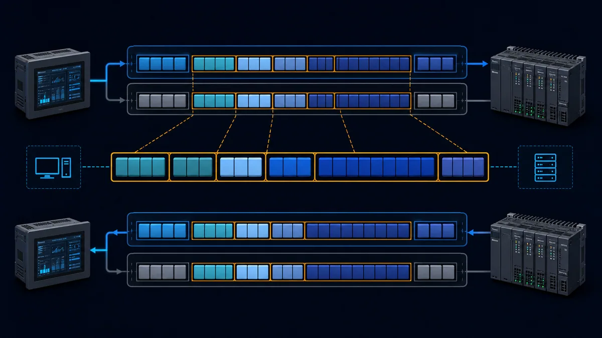
The Modbus Protocol Data Unit, or PDU, is the function code followed by function-specific data. A transport adds an Application Data Unit wrapper. Modbus TCP adds an MBAP header containing transaction, protocol, length and unit identifiers. Modbus RTU places a server address before the PDU and a CRC after it. The underlying function semantics remain recognizable, but a TCP capture and an RTU capture should not be parsed as identical byte streams.
Example read-holding-register request
Consider a PDU requesting three holding registers starting at address 0x006B:
| PDU field | Example | Meaning |
|---|---|---|
| function | 03 |
read holding registers |
| starting address high | 00 |
high byte of starting address |
| starting address low | 6B |
low byte; combined start is 0x006B |
| quantity high | 00 |
high byte of quantity |
| quantity low | 03 |
request three 16-bit registers |
A successful response starts with 03, then a byte count of 06, then six data bytes representing three 16-bit register words. That alone does not decide whether two words form a 32-bit float, signed integer or swapped-order value. Data type and multiword order come from the device map.
Normal response correlation
For Modbus TCP, correlate the response's transaction identifier with the request and verify the unit identifier used by the device or gateway. For Modbus RTU, verify address, timing boundaries and CRC. In both transports, confirm the returned function and function-specific byte counts before interpreting application data.
| Validation step | Modbus TCP evidence | Modbus RTU evidence |
|---|---|---|
| request reached intended path | destination IP/port, connection and transaction | physical segment, server address and transmit activity |
| response belongs to request | matching transaction identifier and unit context | expected server address within request-response timing |
| frame is structurally usable | MBAP protocol/length plus PDU length | address, complete PDU and valid CRC |
| function succeeded | original function code | original function code |
| function failed with exception | original function plus 0x80, then exception byte |
original function plus 0x80, then exception byte |
How the exception function is formed
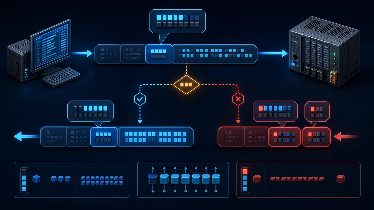
When the server returns a protocol exception, it sets the most-significant bit of the requested function. For public functions below 0x80, that is commonly described as adding 0x80.
Transformation examples
| Requested operation | Request function | Exception function | Example exception PDU |
|---|---|---|---|
| Read Coils | 01 |
81 |
81 02 for illegal data address |
| Read Holding Registers | 03 |
83 |
83 02 for illegal data address |
| Write Single Register | 06 |
86 |
86 03 for illegal data value |
| Write Multiple Coils | 0F |
8F |
8F 01 for illegal function |
| Write Multiple Registers | 10 |
90 |
90 04 for server device failure |
| Read/Write Multiple Registers | 17 |
97 |
97 06 for server busy |
The second byte in each example is the exception code. An 83 response is not “exception code 83”; it is the exception form of function 03. The following byte supplies the actual exception reason.
Exception-code reference and first checks
An exception narrows the search, but it does not prove one physical component failed. A server may expose a gateway's downstream failure, reject a valid-looking range because one element is unavailable, or map an internal application state to a generic exception. Preserve the exact request and response before changing configuration.
Standard diagnostic meanings
| Code | Standard name | What it establishes | High-value first checks |
|---|---|---|---|
01 |
Illegal Function | the receiving server does not allow that function in the current implementation/state | device-supported function list, server mode, write enable, firmware capability |
02 |
Illegal Data Address | at least one addressed item is not valid for that function/request | zero-based offset, table selected by function, start plus quantity, model/firmware map |
03 |
Illegal Data Value | a request field/value is not accepted | quantity limit, byte count, encoded coil value, subfunction, application constraints |
04 |
Server Device Failure | unrecoverable error occurred while the server attempted the action | device diagnostics, application state, logs, repeat with a known-good read |
05 |
Acknowledge | request accepted but processing needs longer | documented long-operation workflow and later completion query |
06 |
Server Device Busy | server is occupied with a long-duration command | controlled backoff, device state, avoid aggressive retry loops |
08 |
Memory Parity Error | server detected a memory parity problem during file-record access | device diagnostics and manufacturer service guidance |
0A |
Gateway Path Unavailable | gateway could not allocate or use the intended path | route/channel configuration, downstream port state, gateway resource/diagnostic status |
0B |
Gateway Target Device Failed to Respond | gateway did not receive a response from the downstream target | unit mapping, downstream address, serial settings, wiring, target power and timing |
Codes 05 and 06 should not trigger a tight, unbounded retry loop. Honor the product's documented polling and completion mechanism. A busy device can remain busy longer when clients add more traffic.
Device-specific extensions and aliases
Some products expose extra exception values or translate internal results into labels. Others show a local software enumeration such as “invalid response,” “connection closed” or “timeout.” Record the raw protocol bytes alongside the tool's description. If the packet contains no exception PDU, the client label must not be treated as an on-wire exception code.
Schneider Electric's Modbus handling documentation, for example, distinguishes application results such as timed out, invalid response and received exception. That separation is useful even when another vendor uses different enumeration values: protocol evidence and client-runtime results belong in different fields.
Live mini-lab
Try it: press START, then STOP
A stop-dominant seal-in rung: START latches the motor output through its own contact, and STOP breaks the circuit.
Watch the output lamp: it stays on after START until you press STOP.
Free to start · runs in your browserOpens plcsimulationsoftware.com — same team
Timeout, malformed frame and exception are different outcomes
A responding server that sends 83 02 has demonstrated substantially more of the path than a silent transaction. The request crossed the transport, reached a Modbus endpoint, was parsed far enough to identify function 03, and produced a protocol reply. Focus on the selected table, offset and range. With a timeout, first prove transport, unit routing, serial framing and response timing.
Outcome decision table
| Observed outcome | What is proven | What is not proven | Next diagnostic branch |
|---|---|---|---|
| valid normal response | endpoint, function and requested range were accepted | semantic interpretation of returned words | verify data type, scaling, word order and process plausibility |
| valid exception response | endpoint received and rejected/failed the request | exact hardware cause beyond returned reason | use exception-specific checks and device diagnostics |
| TCP reset/refused | network path reached a host or intermediary | active Modbus service and valid unit route | service/port, connection limits, firewall and endpoint configuration |
| client timeout with no captured reply | client did not accept a reply in time | whether request reached server or reply left it | capture both sides; verify routing, unit ID, serial path and timeout |
| RTU request with bad/no response and CRC errors | physical activity exists but valid frame was not accepted | correct polarity, format, timing and signal quality | use RS-485 wiring diagnostics, serial settings and waveform evidence |
| structurally malformed response | some responder returned unusable data | whether target server or gateway generated it | raw capture, transaction correlation, length/CRC and gateway firmware |
Evidence to save before retrying
Save the timestamp, client and server endpoints, unit/server identifier, transport, transaction identifier where applicable, raw request/response, decoded function, start address, quantity, exception byte, round-trip time, device state and any gateway status. A screenshot that says only “Modbus error” discards most of the evidence needed to reproduce the fault.
| Evidence field | Example | Why it matters |
|---|---|---|
| transport | TCP, RTU over RS-485, RTU through TCP gateway | determines frame wrapper and failure points |
| function notation | decimal 3 / hex 03 | prevents decimal/hex ambiguity |
| wire start address | 0x006B / decimal 107 |
separates PDU offset from human reference notation |
| quantity | 3 registers | detects range crossing and byte-count errors |
| raw result | 83 02 |
distinguishes exception function from exception reason |
| elapsed time | 243 ms | exposes response-delay and timeout-policy issues |
| unit ID | 7 | essential for bridges and multi-drop routing |
| device identity | exact model, firmware, option | register maps and supported functions can differ |
Illegal Function exception 01
Exception 01 means the server does not recognize or permit the requested operation in its implementation or current state. It does not mean “all communications are broken.” Because a valid exception came back, the response path works at that moment.
Diagnose capability before configuration churn
Confirm that the device implements the exact function. Some read-only instruments support 03 but reject writes. Some expose a value through 04 rather than 03. A gateway may support a function on one route but not translate it to a downstream protocol. A device can also gate commands by run state, access level or an enabled-server setting.
Use a known-good read documented for the exact model. If that succeeds, compare its function with the failed request. Do not “solve” a rejected write by cycling through other write functions on live machinery.
| Candidate cause | Discriminating check | Safe action |
|---|---|---|
| unsupported function | compare current manual's supported-function table | choose documented function or stop integration |
| correct capability but wrong server mode | inspect enabled service, role and write permissions | change only through approved configuration control |
| gateway cannot translate function | test gateway's documented support against simulator | select supported mapping or architecture |
| command disallowed in present device state | correlate status, mode and access state | follow manufacturer transition procedure |
| firmware/model mismatch | record exact identity and compare map revision | use matching documentation; validate in test system |
Illegal Data Address exception 02
Exception 02 means the addressed item or combination is invalid for that request. The starting address may be wrong, the function may select the wrong table, the requested block may extend beyond a valid range, or the installed model may not contain the optional object shown in another manual.
Validate the entire interval
A start address can be valid while start + quantity - 1 crosses the end of a block, a reserved hole or a maximum transfer boundary. Reduce the test to one documented item. If the single-item read works, expand the quantity carefully until the invalid boundary is identified. Keep function and start constant during that experiment.
| Observation | Likely interpretation | Next controlled test |
|---|---|---|
every address returns 02 |
wrong function/table, reference conversion or map revision | test one manufacturer example exactly |
| first register works; larger quantity fails | block boundary, gap or quantity constraint | find last valid item with small increments |
| neighboring block works with another function | logical table mismatch | use the function specified for that object |
gateway returns 02 only for one unit |
unit-specific map or downstream translation | compare route and device identity |
| address works on one model, not another | option/firmware/product-family variation | use installed-model documentation |
Illegal Data Value exception 03
Exception 03 says a field contained a value the server does not accept. It often applies to quantity, byte count, encoded output value, diagnostic subfunction or an application-restricted value. It is distinct from exception 02, which concerns the addressed objects.
Check field consistency and limits
For multiple writes, verify that quantity and byte count agree and that the payload contains the declared number of values. For function 05, the standard ON and OFF encodings are specific 16-bit values; arbitrary nonzero values are not equivalent to ON. For function 16, check the device's maximum register count and whether the requested values are permitted in the current operating state.
| Request type | Frequent value fault | Check |
|---|---|---|
| Read Coils/Discrete Inputs | zero or excessive quantity | standard limit plus stricter device limit |
| Read Registers | zero/excessive quantity | range length and response-size capability |
| Write Single Coil | invalid 16-bit ON/OFF encoding | exact encoded value, not Boolean assumption |
| Write Multiple Coils | byte count does not match packed quantity | ceil(quantity / 8) and unused final bits |
| Write Multiple Registers | byte count differs from twice quantity | two bytes per 16-bit word and device limit |
| Mask Write Register | incorrect AND/OR masks | documented mask formula and target support |
Server failure, acknowledge and busy exceptions
Exceptions 04, 05 and 06 concern execution rather than a simple unsupported function or invalid address. Preserve device state and internal diagnostic evidence. Repeatedly issuing the same action may obscure or worsen the condition.
Separate transient state from persistent failure
Use one known-good, read-only status request to determine whether the server remains generally responsive. For 05, follow the specification and device's documented long-operation completion method. For 06, apply bounded backoff and inspect the operation occupying the server. For repeatable 04, collect device diagnostics, firmware, resource state and the smallest request that reproduces the failure before escalation.
| Exception | Immediate response | Avoid |
|---|---|---|
04 server device failure |
save raw request/response and internal diagnostic/log snapshot | blind reboot before preserving evidence |
05 acknowledge |
follow documented completion/polling procedure | interpreting acknowledge as completed work |
06 server busy |
bounded delay, then approved retry count | millisecond retry storms from several clients |
repeated 04 on one range |
single-item read and device-map verification | bulk writes or broad production probing |
Gateway exceptions 0A and 0B
A Modbus TCP-to-serial gateway can answer on Ethernet while the downstream target remains unreachable. Exception 0A indicates a gateway path problem; 0B indicates that the target device behind the gateway did not respond. They direct investigation to different levels, but product implementations and local diagnostics still matter.
Follow the route from unit ID to field device
Verify how the gateway maps the Modbus TCP unit identifier to a serial address, channel or configured route. Then confirm downstream baud, parity, stop bits, address uniqueness, RS-485 polarity/topology/termination, target power and response timing. A successful TCP socket connection proves only the Ethernet-facing service.
| Finding | More consistent with | Evidence to collect |
|---|---|---|
| all units on one gateway channel fail | path unavailable or channel/configuration fault | gateway channel status, route and serial-port counters |
| one unit fails while neighbors respond | target no-response, duplicate/wrong address or local wiring | per-unit request capture, node power and segment location |
| reply appears downstream but not upstream | gateway correlation, timing or parsing issue | simultaneous Ethernet and serial captures |
| unit works direct but not through gateway | route/unit translation or gateway function support | exact mapping, firmware and function matrix |
| gateway produces no exception and TCP client times out | gateway/service/connection problem rather than returned 0A/0B |
socket trace, gateway log and connection limits |
Register addresses, references and offsets
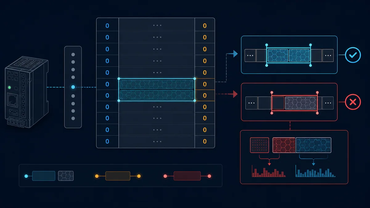
The address field in a Modbus PDU is a zero-based 16-bit address within the logical table selected by the function. Traditional human-facing notation such as 40001 is not transmitted as the five-digit number 40001. If a manufacturer says holding register 40001 and follows the traditional convention, its wire offset is normally zero with function 03 or an applicable holding-register operation.
Treat each manual's notation as an explicit rule
Manufacturers and software tools do not label addresses consistently. A column called “address” may already be zero-based; another may show one-based register references; a client UI may ask for 40001, 1, or 0 for the same object. Never apply “subtract one” until the documentation and client field definition are known.
| Manual or tool presents | Possible intended wire offset | Required confirmation |
|---|---|---|
| holding register 40001 | 0 | manual states traditional 4xxxx reference notation |
| holding register 40002 | 1 | same notation and function 03/holding-register context |
| address 0 | 0 | column explicitly says protocol/PDU/zero-based address |
| address 1 | 1 or 0 | whether column is zero-based address or one-based reference |
%MW0 or vendor tag |
product mapping determines it | device's Modbus mapping table, not PLC memory syntax alone |
| client field “register 1” | client setting determines it | client documentation for base and reference interpretation |
Word order is a separate problem
Each Modbus register is 16 bits and is transmitted with the high-order byte first inside the register. How a product maps a 32-bit integer, float or 64-bit value across several registers is an application convention. If a read succeeds but the number is implausible, keep the working function and address fixed while testing the documented type, scale and word order. Do not misclassify a semantic decoding problem as an exception.
Safe test sequence for client and server commissioning
Begin with a read-only request documented by the device manufacturer. Use an approved test environment or simulator for deliberate invalid requests. A Modbus write can change outputs, setpoints, operating modes or stored configuration; on production machinery it can cause motion or defeat process assumptions. Follow site authorization, risk controls and lockout/tagout procedures where hazardous energy is involved.
A nine-step evidence ladder
- Record the exact server model, firmware, communication option and manual revision.
- Prove the transport: IP route and service for TCP, or physical/serial layer for RTU.
- Confirm the server or unit identifier and that no duplicate serial address exists.
- Select one manufacturer-documented read-only object and its required function.
- Convert the printed reference to the client field only after confirming both conventions.
- Request one item and save the raw request, raw response and elapsed time.
- Interpret normal data using the documented type, scaling and word order.
- In a simulator, send one intentionally invalid function, address and value to learn the client's displays.
- Add production quantities or writes only under change control with rollback and outcome verification.
| Test | Controlled request | Expected evidence | Diagnostic value |
|---|---|---|---|
| known-good read | one documented register | normal function and two data bytes | baseline endpoint/function/address path |
| adjacent valid read | next documented item | normal response | exposes isolated map assumptions |
| invalid address in simulator | out-of-map single item | exception function plus 02 |
proves client displays protocol exception correctly |
| invalid quantity/value in simulator | zero/excess or inconsistent payload | exception plus 03 when implemented |
separates value validation from address validation |
| unsupported function in simulator | configured unsupported operation | exception plus 01 |
validates high-bit decoding |
| simulated silence | no server reply | client timeout, no exception PDU | validates timeout classification |
| delayed simulator reply | response around timeout boundary | measured accept/reject threshold | supports timeout policy without production guessing |
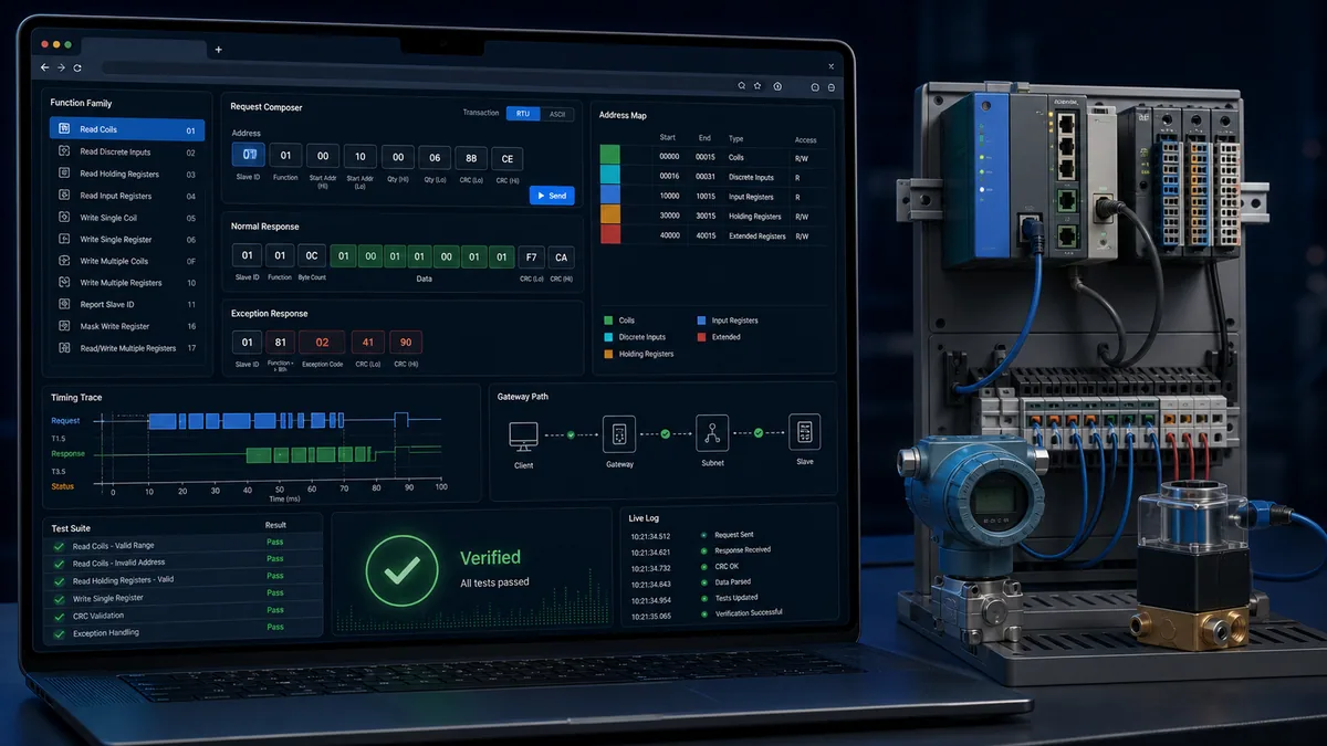
Use the Modbus simulator to create known-good and deliberately invalid test cases before connecting a new client to field equipment. For RTU signal problems, pair protocol tests with the RS-485 wiring and diagnosis guide. For a broader frame walkthrough, see the Modbus RTU protocol tutorial.
Troubleshooting workflows by symptom
The fastest workflow changes one independent variable at a time and predicts the result before sending the request. When an address is suspect, do not simultaneously change function, base convention, quantity and timeout. A success would be impossible to attribute.
Every read returns illegal address
Start with the installed-device map, not a search-result snippet from a related model. Confirm the object table, required function, manual's base convention, optional hardware and firmware. Request exactly one object from a manufacturer example. If the client UI accepts reference notation, confirm whether it subtracts the table prefix and one automatically.
Intermittent exception and timeout mixture
Exceptions prove that some transactions reach a responding endpoint; timeouts prove only that the client did not accept a response in time. Correlate both to request type, unit, load, device mode and physical/network counters. If only large reads fail, examine range boundaries and response size before increasing timeout. If all functions intermittently disappear, examine transport, gateway load and—for RTU—the intermittent PLC fault workflow.
Writes fail while reads work
Prove whether the write function is supported and enabled, whether the object is writable, whether the value and quantity are valid, and whether the current device state permits the change. A successful read does not authorize or guarantee a write. Compare access level, remote/local state, run mode, interlocks and security settings using the vendor procedure.
Wrong values with no exception
A normal response says the server accepted the request; it does not certify that the client chose the intended object or decoded it correctly. Check one-based versus zero-based mapping, 03 versus 04, signedness, scale, engineering units, bitfield definition, byte order within each register and word order across registers. Compare the raw words with a known physical condition.
Diagnostic answer map for search and AI-assisted troubleshooting
This answer map states the shortest defensible response to common natural-language queries. It is designed for technicians, search systems and AI assistants to extract an answer without losing the conditions that make it accurate.
| User or AI query | Concise answer | Required qualification |
|---|---|---|
| What does Modbus function code 03 do? | It reads one or more holding registers. | The individual device must implement 03, and its map defines valid offsets and data meaning. |
| What is the difference between function 03 and 04? | 03 selects holding registers; 04 selects input registers. |
Similar printed addresses do not make the two logical tables interchangeable. |
| Why did function 03 return 83? | 83 is the exception form of 03; inspect the following exception byte. |
83 is not itself the reason code. |
| What is Modbus exception 02? | Illegal Data Address: some addressed item/range is invalid for that function. | Check table, zero-based offset, whole quantity and installed model map. |
| What is Modbus exception 03? | Illegal Data Value: a request field/value or quantity is unacceptable. | Device/application constraints can be stricter than protocol maxima. |
| Is a Modbus timeout an exception code? | No. A timeout means the client accepted no timely response; a protocol exception is a returned PDU. | Client software may group both under a vendor-specific error API. |
| Does Modbus send register 40001 on the wire? | No; traditional 40001 normally maps to offset zero in the holding-register table. | Confirm the manual and client addressing conventions before subtracting one. |
| What does gateway exception 0B mean? | The gateway did not receive a response from the intended downstream target. | Investigate unit mapping, downstream address/settings, wiring, power and timing. |
| Can I test all function codes against a PLC? | Do not sweep unknown functions on production equipment. | Use an approved simulator or test device and a documented function matrix. |
| How do I debug wrong Modbus float values? | Keep the successful request fixed and verify type, scaling and multi-register word order. | A normal response can still be decoded with the wrong application convention. |
Frequently asked questions
What are the most common Modbus function codes?
The most common are 01 read coils, 02 read discrete inputs, 03 read holding registers, 04 read input registers, 05 write one coil, 06 write one register, 0F write multiple coils and 10 write multiple registers. Device support is not universal, so confirm the exact model and firmware manual.
How do I calculate a Modbus exception response function?
Set the request function's most-significant bit, usually described as adding hexadecimal 0x80. Function 03 becomes 83; function 10 becomes 90. The following byte is the exception reason code.
What does Modbus exception code 01 mean?
Exception 01, Illegal Function, means the server does not recognize or permit that function in its implementation or present state. Confirm supported functions, server mode, permissions, gateway translation and installed firmware before changing addresses.
What does Modbus exception code 02 mean?
Exception 02, Illegal Data Address, means at least one requested item is invalid for that function. Verify the logical table, zero-based PDU offset, start-plus-quantity interval, installed options and matching register-map revision.
What does Modbus exception code 03 mean?
Exception 03, Illegal Data Value, means a request field or value is unacceptable. Common causes include an invalid quantity, inconsistent byte count, invalid single-coil encoding, unsupported subfunction or a value prohibited by current application state.
Why is my Modbus client showing an error but no exception code?
The failure may be local or transport-level: timeout, socket error, connection refusal, CRC rejection, malformed frame or configuration error. Capture the raw traffic. A genuine Modbus protocol exception contains an exception function and one-byte reason.
Is holding register 40001 address zero or one?
In traditional reference notation, holding register 40001 maps to PDU address zero. But many manuals and client tools already display zero-based addresses or apply their own conversion. Confirm both definitions before subtracting one.
Why does a one-register read work while a block read returns exception 02?
The larger request may cross a valid block boundary, reserved gap, option-dependent area or device quantity limit. Keep the start fixed and expand the quantity in controlled steps using the exact installed-device map.
What is the difference between gateway exceptions 0A and 0B?
Exception 0A means the gateway could not use or allocate the intended path. Exception 0B means it used the route but the downstream target did not answer. Product diagnostics should confirm the actual route and target condition.
Can a Modbus simulator help diagnose production errors safely?
Yes. A simulator can reproduce normal responses, exceptions, delay and silence so the client's decoding and timeout policy can be verified without sending experimental writes or unsupported functions to production equipment. Final commissioning still requires the installed device manual and approved field tests.
Sources, review scope, and limitations
This guide was reviewed against the Modbus Organization specification and current manufacturer documentation available on August 28, 2026. The Modbus application specification defines protocol semantics, but an installed product's manual remains authoritative for its supported functions, register map, quantities, server/gateway behavior, data types, timing and firmware-specific limitations.
- MODBUS Application Protocol Specification V1.1b3 — Modbus Organization
- Modbus specifications and implementation guides — Modbus Organization
- Introduction to Modbus — Modbus Organization
- IOS_GETDIAGSTATUS diagnostic status — Schneider Electric
- ModbusServer function block — Schneider Electric
- Modbus implementation for PM8000 — Schneider Electric
- ET_Result Modbus handling results — Schneider Electric
- Control of hazardous energy: lockout/tagout — OSHA
The generated illustrations are conceptual teaching aids, not packet captures, register maps, wiring diagrams or product configuration instructions. Verify byte-level conclusions with a raw capture and the specification. Verify any field action against the exact device documentation, site risk assessment and change-control procedure. No universal timeout, retry count, register base or word order is safe to assume across every implementation.
Now run it · free to start
Learn Modbus, then the networks around it
Modbus first because it is simple and everywhere, then the Ethernet-based protocols and the SCADA layer above them. Free to start.
Ownership disclosure: PLC Programming IO and PLC Simulation Software are operated by the same publisher.
PLC Programming IO Editorial Team
Industrial automation education, references, and software testing
The PLC Programming IO Editorial Team publishes sourced industrial-automation education and documents how material is reviewed, tested, and corrected. A team byline means the publisher is responsible for the page; it does not represent a fictional person or imply an engineering licence.
Coverage:
- • PLC programming concepts and examples
- • Vendor software tutorials and comparisons
- • SCADA, HMI, protocols, and instrumentation
- • Training, careers, and reference material
Review standard:
- • Prefer primary and official sources
- • Record software versions when material
- • Separate tested facts from estimates
- • Publish material corrections
Important scope note
This site provides education, not project-specific engineering approval. Safety, code, and compliance decisions require a qualified person with access to the actual machine and jurisdiction.