EtherCAT for PLC Motion and I/O Systems
Understand EtherCAT frame processing, topology, ESI configuration, PDO mapping, device states, distributed clocks and working-counter diagnostics in PLC systems.
Review status: Editorially reviewed against cited EtherCAT Technology Group and current vendor documentation; exact MainDevice, SubDevice, cable, timing and safety behavior requires installed-product verification
Direct answer
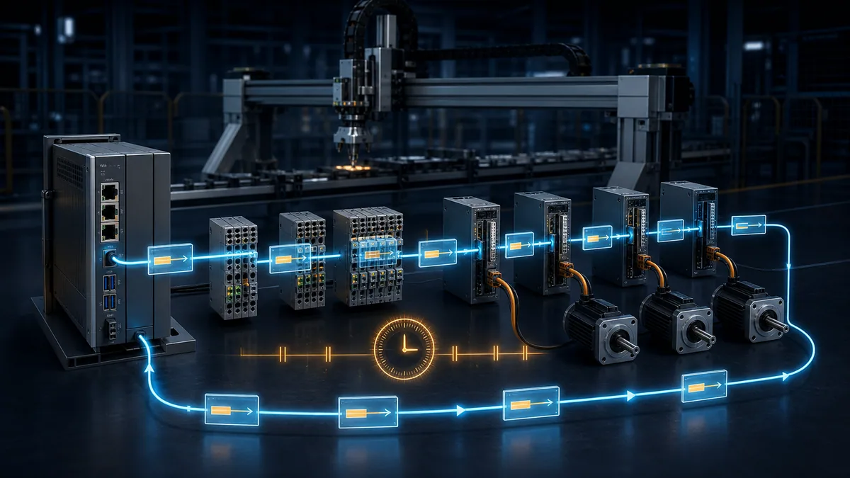
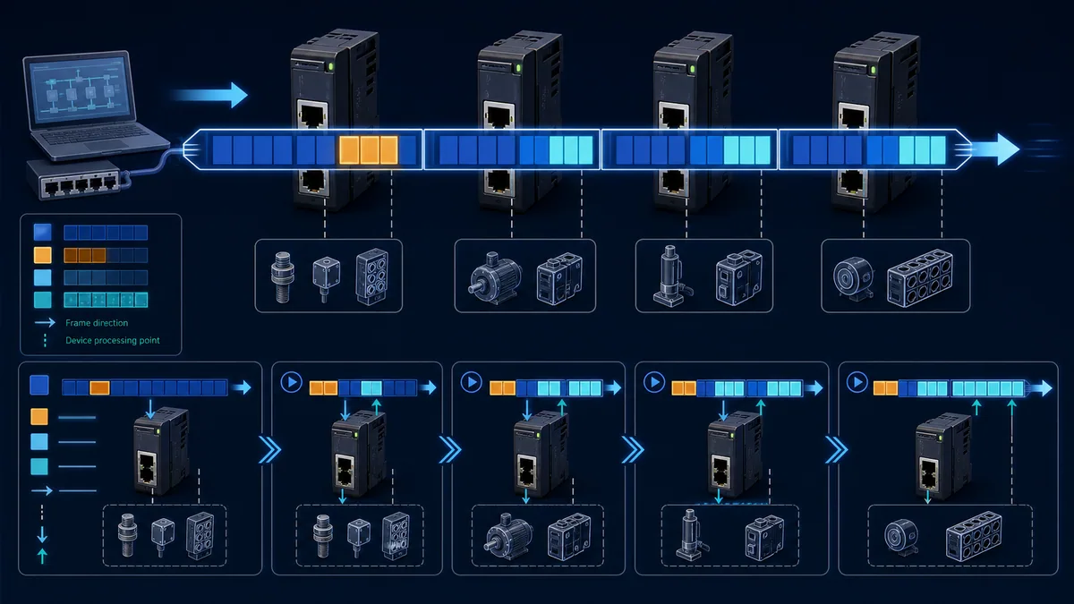
EtherCAT is a real-time Industrial Ethernet system used to connect a PLC or industrial PC MainDevice to distributed I/O, servo drives, encoders, robots and other SubDevices. The MainDevice sends frames through the network; each SubDevice reads output data addressed to it and inserts input data while the frame passes, then the last open port returns the frame through the full-duplex path. This on-the-fly processing lets one frame serve many devices with predictable cyclic exchange.
To configure EtherCAT in a PLC project, first prove that the controller/runtime and network interface support acting as an EtherCAT MainDevice. Obtain the exact SubDevice's EtherCAT SubDevice Information, or ESI, file; match the discovered product/revision; create the expected topology; select cyclic Process Data Objects, or PDOs; map them to typed PLC variables; set the bus/task cycle and watchdog behavior; configure Distributed Clocks only where the application and devices require them; and commission devices through INIT, PREOP, SAFEOP and OP with a defined safe-output test.
To diagnose EtherCAT, preserve the first fault and compare expected topology, actual device order, link state, EtherCAT state, AL status code, expected versus actual Working Counter, per-port receive/CRC and lost-link counters, and Distributed Clock deviation. A Working Counter mismatch proves that a datagram did not receive the expected participation; it does not by itself identify a bad cable or name the failed device. Use topology and per-port counters to localize the boundary.
Use current EtherCAT terminology
The EtherCAT Technology Group now uses MainDevice and SubDevice in public technology descriptions. Many installed manuals, engineering tools and object names still use the legacy terms master and slave. Both pairs refer to the initiating controller and the devices that process its frames. When searching a product manual, use the terminology printed by that product without assuming an architectural difference.
Core terms
| Term | Practical meaning | Common mistake |
|---|---|---|
| MainDevice | controller/stack that configures the network and initiates EtherCAT frames | assuming any Ethernet PLC port can become a MainDevice |
| SubDevice | I/O, drive, encoder, coupler or controller interface that processes passing frames | treating it like a normal TCP server with an IP address |
| ESC | EtherCAT SubDevice Controller implemented in ASIC, FPGA or MCU integration | confusing ESC register diagnostics with application parameters |
| ESI | XML description of a SubDevice's identity, ports, PDOs, mailbox/profile and capabilities | using an ESI for a related revision without checking identity |
| ENI | generated network-configuration information used by a MainDevice implementation | treating an ESI for one device as the complete network configuration |
| SII | identity/configuration information stored in a SubDevice's local information interface/EEPROM | assuming online SII and installed ESI always agree |
| PDO | cyclic process data mapped between SubDevice and controller process image | reversing RxPDO and TxPDO direction |
| mailbox | acyclic channel for configuration, diagnostics and protocols such as CoE | expecting mailbox transfers to behave like cyclic PDOs |
| Working Counter | datagram field incremented according to successful addressed operations | reading any nonzero value as automatically healthy |
| Distributed Clocks | hardware-supported common time and synchronized events in capable devices | enabling DC without proving required mode/cycle support |
Understand on-the-fly frame processing
The MainDevice is the only node in an EtherCAT segment that actively originates EtherCAT frames. SubDevices forward the frame downstream while reading from and writing to assigned locations. The last open port closes the logical path and the full-duplex return travels back through the nodes to the MainDevice.
One frame can serve many devices
| Concept | EtherCAT behavior | Diagnostic implication |
|---|---|---|
| frame origin | MainDevice transmits cyclic EtherCAT frames | a silent MainDevice or wrong network interface stops the segment |
| device handling | hardware processes selected bytes while forwarding | a device can have link yet fail state/configuration or data access |
| return path | open downstream port returns the frame through full duplex | physical topology is interpreted as a logical processing path |
| datagrams | frame can contain one or more EtherCAT commands/address ranges | Working Counter expectation belongs to the specific datagram |
| Ethernet framing | EtherCAT uses standard Ethernet framing, commonly EtherType 0x88A4 |
packet capture can decode EtherCAT, but capture placement matters |
| ordinary IP | cyclic EtherCAT device exchange is not configured as normal TCP/IP polling | ping is not the primary proof of a SubDevice's EtherCAT state |
EtherCAT can carry Ethernet over EtherCAT as an optional mailbox profile, but that does not turn the cyclic fieldbus into an unmanaged office-LAN chain. Use EtherCAT infrastructure components and the device/manufacturer topology rules.
Select the PLC and MainDevice interface
The first compatibility question is not “does the PLC have Ethernet?” It is “does this exact PLC/runtime, firmware and interface implement the required EtherCAT MainDevice class and features?” Motion may require Distributed Clocks, specific cycle times, CiA 402 profile support and coordinated task scheduling that a basic I/O MainDevice does not provide.
MainDevice capability checklist
| Capability | Evidence to request | Consequence if absent |
|---|---|---|
| supported MainDevice stack | controller/runtime documentation and approved network adapter | no EtherCAT network initiation |
| ESI import and scan | engineering-tool device repository workflow | device cannot be configured or is reduced to generic handling |
| required mailbox profiles | CoE, SoE, FoE, EoE or vendor protocol support as needed | parameters, firmware or diagnostics unavailable |
| flexible PDO mapping | static/dynamic mapping support compatible with SubDevice | process image differs from application expectation |
| Distributed Clocks | supported modes, reference-clock handling and diagnostics | synchronized I/O/motion cannot meet design |
| cycle/task integration | minimum/supported cycles, jitter and task binding | bus timing can be inconsistent with PLC/motion task |
| topology/hot connect/redundancy | exact optional functions | modular/redundant architecture may not work as designed |
| diagnostic access | AL status, Working Counter, port counters and DC state | commissioning and maintenance evidence is weakened |
Brand compatibility needs an exact product answer
Beckhoff controllers and TwinCAT are closely associated with EtherCAT, but still require compatible terminals, ESI data and configuration. Use the Beckhoff EtherCAT TwinCAT 3 setup, PDO mapping and diagnostics guide for the exact target, real-time adapter, scan/diff, Startup, task/DC and Working Counter workflow. CODESYS-based controllers can support an EtherCAT MainDevice when the target runtime, license, driver and network interface support it; “uses CODESYS” alone is insufficient. Siemens S7-1200 controllers are ordinarily configured around their documented PROFINET capabilities; an EtherCAT connection generally needs a supported gateway or separate motion controller rather than an assumption of native MainDevice support. Use the S7-1200 EtherCAT gateway, mapping and diagnostics guide to select the correct PROFINET-device/EtherCAT-MainDevice or controller-to-controller role pair. Rockwell controllers are ordinarily associated with EtherNet/IP; the Allen-Bradley EtherCAT gateway, Studio 5000 mapping and diagnostics guide explains the required Scanner/Adapter and MainDevice/SubDevice role pairs without implying native compatibility. Current OpenPLC Runtime v4 includes a native plugin route, but support still depends on the exact release, host, plugin, dedicated NIC and device project; use the OpenPLC EtherCAT v4 setup and diagnostics guide for that product-specific path.
Verify each claim in the current controller and interface manuals. Do not choose a gateway solely because both product pages say Ethernet; it must implement the correct roles, cyclic data sizes, timing, state and fault behavior.
Build the topology and cabling correctly
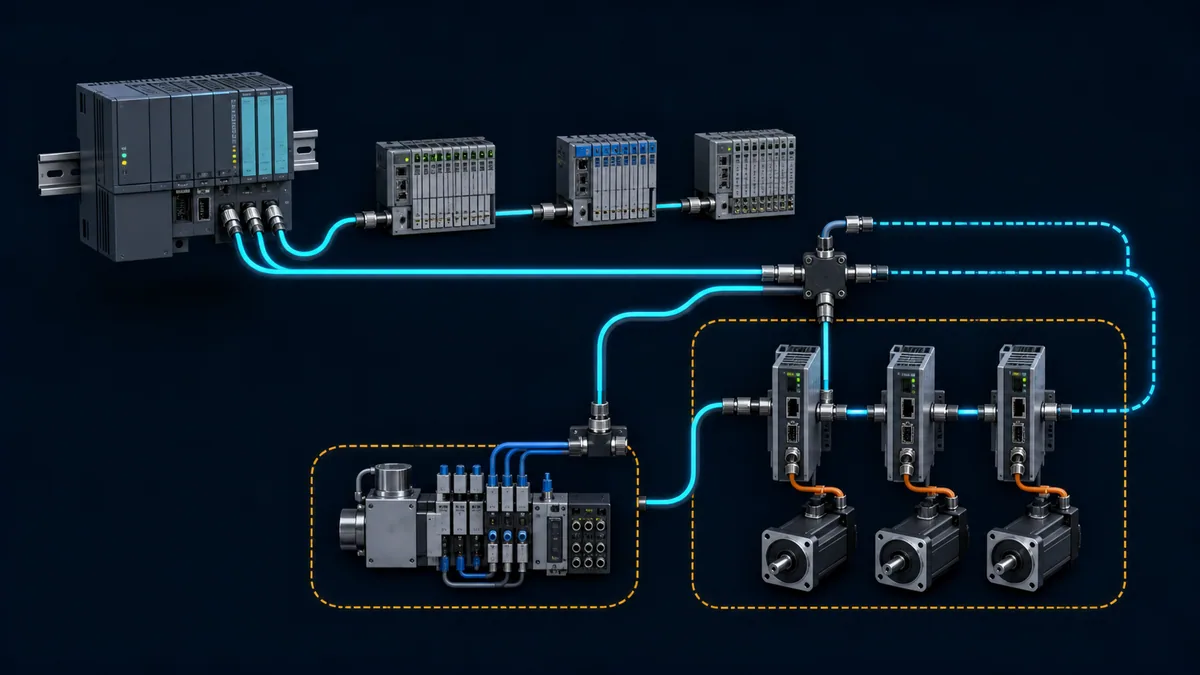
EtherCAT supports line, tree, star and branch structures using the ports and junctions provided by EtherCAT devices. Its physical arrangement can be flexible while the logical frame path remains deterministic and discoverable. A standard office Ethernet switch inserted into the real-time device path is not equivalent to an EtherCAT junction.
Topology evidence
| Design item | Record in the as-built | Commissioning proof |
|---|---|---|
| MainDevice port/NIC | controller, interface, MAC/driver and cable origin | correct interface is bound to EtherCAT and sends frames |
| device order | every coupler, terminal, drive and port path | scan order/identity matches project expectation |
| branch/junction | input and each numbered output port | branches appear in the intended topology position |
| copper/fibre segment | medium, connector, cable category/rating, route and length | link and error counters stable under operating environment |
| machine-module connection | detachable connector and hot-connect group if used | removal/rejoin behavior matches approved design |
| redundancy | primary/return route and supported MainDevice mode | controlled single-break test and recovery evidence |
| power architecture | electronics, field power and EtherCAT P where applicable | node power loss produces predicted topology/fail state |
For common 100BASE-TX copper links, the often-cited maximum is 100 m between devices, but the installed cable, connector, flex duty, EMC environment and device manual determine the valid segment. EtherCAT P combines communication and power under its own system rules; it is not ordinary Power over Ethernet. Fibre and other physical variants require compatible devices.
Live mini-lab
Try it: press START, then STOP
A stop-dominant seal-in rung: START latches the motor output through its own contact, and STOP breaks the circuit.
Watch the output lamp: it stays on after START until you press STOP.
Free to start · runs in your browserOpens plcsimulationsoftware.com — same team
Import ESI and match device identity
An ESI file describes one or more SubDevice types and revisions: identification, physical ports, process data, SyncManagers, mailbox protocols, Distributed Clock modes and other capabilities. Import it into the engineering tool's device repository using the tool's supported workflow.
Resolve ESI and scan mismatches
| Symptom | Candidate cause | Correct action |
|---|---|---|
| discovered device is unknown | ESI not installed or repository path/version wrong | obtain current ESI from device manufacturer; restart/update repository as required |
| product code matches, revision differs | hardware/firmware revision not described by selected entry | use manufacturer compatibility guidance; do not disable identity checks blindly |
| duplicate/outdated ESI entries | several files describe same family with different dates | retain controlled source/version and remove unintended repository conflicts |
| scanned order differs from project | cable/port order, inserted terminal or branch changed | reconcile as-built and project intentionally |
| offline device offers PDOs not online | ESI capability differs from SII/firmware or dynamic mapping | verify exact device revision and supported mapping workflow |
| replacement stays PREOP/SAFEOP | startup command/parameter unsupported on new revision | inspect AL status and startup-command failure; update configuration through change control |
Do not download an ESI from an unrelated file archive merely because the filename resembles the device. Use the manufacturer or ETG-listed product source, record the file/version/checksum, and retain it with the project.
Map PDOs to PLC variables
PDOs carry cyclic values. From the SubDevice perspective, RxPDOs are received by the SubDevice—commonly controller commands, target values and output bits. TxPDOs are transmitted by the SubDevice—commonly status, actual values and input bits. Some PLC tools present direction from the controller perspective, so verify the labels in that tool.
Generic drive and I/O mapping example
| Process item | Typical direction | PLC type consideration | Validation |
|---|---|---|---|
| drive control word | MainDevice to SubDevice / RxPDO | unsigned 16-bit bitfield | test each approved transition with status response |
| target velocity/position | MainDevice to SubDevice / RxPDO | signed width and engineering scaling | compare raw and engineering value at safe command |
| drive status word | SubDevice to MainDevice / TxPDO | unsigned 16-bit bitfield | verify ready/switched-on/fault logic from device profile |
| actual velocity/position | SubDevice to MainDevice / TxPDO | signed width, scale and rollover | compare with independent safe observation |
| digital input byte | SubDevice to MainDevice / TxPDO | bit ordering and debounce in application | actuate one channel and confirm raw bit |
| digital output byte | MainDevice to SubDevice / RxPDO | safe default and watchdog behavior | prove OFF state before enabling output |
| analog value/status | SubDevice to MainDevice / TxPDO | signedness, range, status and alignment | apply traceable points and fault condition |
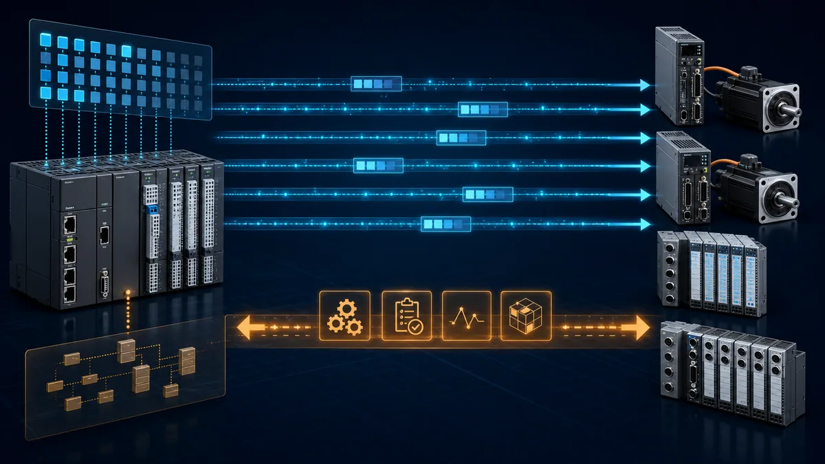
The byte/bit offset shown by the PLC tool is generated from the active PDO configuration. Hard-coding remembered offsets from another device revision is fragile. Map named, typed variables and retain a generated mapping report with the project.
Understand mailbox and device profiles
Mailbox communication supports acyclic protocols while cyclic exchange continues. CAN application protocol over EtherCAT, CoE, exposes an object dictionary and SDO services familiar from CANopen. Servo drives commonly use a standardized drive profile over CoE, but actual modes, objects and PDO choices remain device-specific.
Mailbox protocol roles
| Profile | Purpose | Common use | Limitation |
|---|---|---|---|
| CoE | CANopen application protocol over EtherCAT | object dictionary, SDO parameters, PDO definition, drive profile | object existence/access is device-specific |
| SoE | servo drive profile over EtherCAT | drive parameters for supported servo ecosystems | requires both MainDevice and drive support |
| FoE | file access over EtherCAT | firmware or file transfer where supported | not a universal update method; interruption handling matters |
| EoE | Ethernet over EtherCAT | tunneled Ethernet communication to supported devices | not the real-time cyclic process-data mechanism |
| AoE | ADS over EtherCAT | device/vendor communication and diagnostic access | implementation-specific use |
Startup parameter lists often write mailbox objects as the device moves through states. One rejected SDO can prevent transition to SAFEOP or OP. Preserve the exact object, subindex, abort/AL status and device state instead of deleting all startup commands.
Commission the EtherCAT state machine
EtherCAT SubDevices transition through INIT, PREOP, SAFEOP and OP. A BOOTSTRAP state is available for supported firmware-download functions. The MainDevice requests transitions; the SubDevice reports its Application Layer state and status code.
State behavior and diagnosis
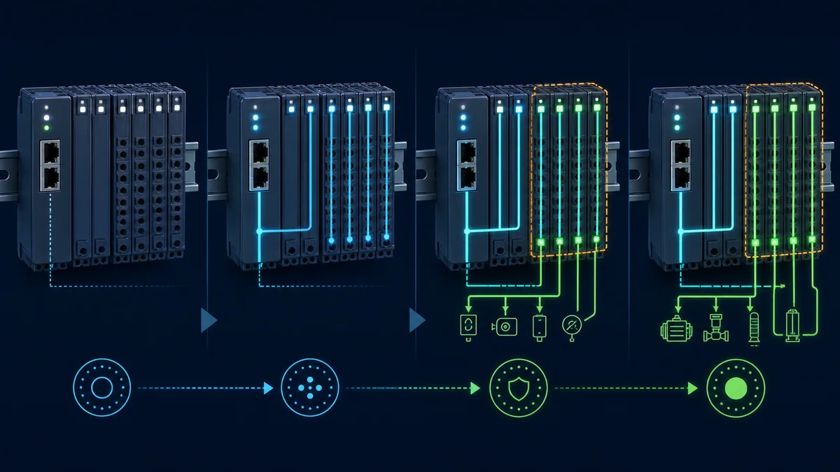
| State | Available behavior in principle | If transition stops here |
|---|---|---|
| INIT | basic ESC/register access; no mailbox/process exchange | identity, power, link, ESC/startup or MainDevice communication issue |
| PREOP | mailbox available; process-data exchange not operational | ESI/startup parameter/mailbox/profile issue |
| SAFEOP | input process data can be exchanged; outputs remain in safe behavior | PDO/SyncManager/DC/watchdog or application readiness issue |
| OP | configured input and output process data active | monitor Working Counter, state, timing and application health |
| BOOTSTRAP | optional firmware/file loading route | use only supported manufacturer process |
State descriptions are protocol principles; the exact output safe value, drive behavior and transition checks come from the SubDevice manual. Never command OP until machine risk controls, output mapping and watchdog/fail state have been validated.
Configure cycle time and Distributed Clocks
The EtherCAT frame cycle, PLC task, motion task, input latch and output update must form a coherent timing design. “EtherCAT is fast” does not guarantee that an overloaded controller task, unsupported adapter or poor application schedule meets a machine's jitter and latency requirements.
Timing design record
| Parameter | Record | Acceptance evidence |
|---|---|---|
| EtherCAT cycle | configured period and MainDevice limit | measured stable cycle under worst planned load |
| PLC/motion task | period, priority, phase and overrun monitoring | no overruns; defined relation to bus update |
| PDO data size | total input/output bytes and datagrams | within MainDevice/device and cycle capability |
| DC reference | selected first/explicit DC-capable device and source | reference stable and topology intentional |
| synchronization mode | free-run, SM-synchronous or DC/SYNC mode per device | device reports supported active mode |
| shift/phase | input latch/output event relative to cycle | measured against application requirement |
| watchdog | device and application timeout/action | controlled missing-frame test produces safe response |
| diagnostic limits | acceptable jitter/deviation/counter behavior | trending and alarm thresholds validated from system evidence |
Distributed Clocks use hardware-supported local clocks and topology-derived propagation delay compensation. The ETG describes synchronization well below one microsecond in suitable implementations, but this is not a universal end-to-end motion accuracy guarantee. Sensor latency, drive loops, mechanical dynamics, MainDevice scheduling and configuration still matter.
Diagnose Working Counter mismatches
Each EtherCAT datagram includes a Working Counter. Devices increment it according to the command and whether the addressed memory operation succeeds. The MainDevice knows the expected value for the configured datagram and compares the returned value each cycle.
Interpret WKC as participation evidence
| Result | Meaning | Next evidence |
|---|---|---|
| actual equals expected | expected addressed operations participated for that datagram | still inspect device/application diagnostics if process is wrong |
| actual lower than expected | one or more expected operations did not participate | identify affected datagram/logical range, device states and topology boundary |
| actual intermittently low | intermittent link, power/reset, state or timing/data-access issue | capture exact cycle plus port counters and state changes |
| actual unexpectedly high | configuration/topology/address expectation mismatch is possible | compare online topology and generated configuration |
| WKC healthy but I/O wrong | mapping, scaling, wiring, application or device process fault | raw PDO values and channel/device diagnostics |
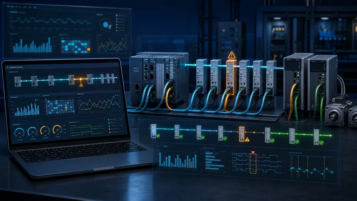
Do not translate “WKC error” directly into “replace the shown terminal.” A fault upstream can remove several downstream devices. A state or PDO configuration issue can affect participation without a physical link loss. First identify which datagram failed, then correlate topology and per-port evidence.
Use link and error counters to localize faults
EtherCAT SubDevice Controllers expose standardized diagnostic registers for port link state and error counters. Vendor tools may label receive errors, CRC/frame errors, forwarding errors and lost-link counters differently, and some counters are optional. Establish a baseline after power-up because switching events can increment counters; counters that continue increasing during normal operation deserve investigation.
Counter-to-cause matrix
| Evidence pattern | More consistent with | Controlled check |
|---|---|---|
| lost-link counter increases on one port | connector/cable movement, device power dip/reset or port hardware | inspect both ends and correlate device power/event time |
| receive/CRC errors begin at a boundary and downstream | signal integrity, cable/connector, EMC or PHY issue near boundary | compare adjacent port counters, cable route and approved substitution |
| many devices disappear after one node | upstream node power/port/cable or branch issue | first missing device and preceding output port |
| states drop without link loss | configuration, watchdog, mailbox/startup or device application fault | AL status code, device diagnostics and WKC/datagram |
| DC deviation grows while frames remain valid | reference/topology/timing configuration or DC device issue | DC reference, mode, task cycle and synchronization diagnostics |
| process value wrong with stable counters/state | PDO mapping, data type/scaling or field channel | raw mapped bytes, ESI/PDO report and channel evidence |
Commission a PLC, I/O and servo network
Use an isolated machine state with torque/energy risks controlled. The sequence below is cross-vendor; the exact commands and safety validation belong to the installed products.
Twelve-step commissioning workflow
- Record MainDevice/runtime, network adapter, firmware, licenses and supported EtherCAT features.
- Inventory every SubDevice's exact identity, revision, ESI source, port order and power needs.
- Draw the expected topology including junction port numbers and detachable machine modules.
- Install controlled ESI files and create/scan the network without enabling outputs.
- Resolve every expected-versus-actual identity and order difference.
- Select PDOs and export a mapping report with direction, offset, type, scale and safe default.
- Configure mailbox startup parameters individually and preserve any abort/status evidence.
- Set bus and PLC/motion task cycles within documented capabilities.
- Configure DC/synchronization only for devices/modes that require and support it.
- Transition INIT to PREOP to SAFEOP while verifying input data, state and AL status.
- Under the approved machine procedure, transition to OP and test one output/axis at a time.
- Inject controlled loss of link/frame or device power in a suitable test system to prove watchdog, diagnostics, safe state and recovery.
| Acceptance surface | Pass evidence | Release blocker |
|---|---|---|
| topology | every expected device/port and no unexplained device | ignored mismatch or auto-accepted wrong revision |
| state | all required devices OP with zero unexplained AL errors | cyclic state drops or hidden optional device missing |
| PDO mapping | raw single-point I/O and drive words match controlled report | guessed offsets, wrong direction/type or stale ESI |
| timing/DC | task/cycle stable and required sync within device/application limit | overruns, drifting reference or unsupported mode |
| diagnostics | expected WKC, counters stable and alarms expose first fault | counters hidden/reset without trending |
| fail behavior | cable/device/MainDevice loss produces approved safe state | outputs hold an unvalidated hazardous command |
| restoration | restart/rejoin follows designed manual/automatic policy | uncontrolled automatic motion after recovery |
Interactive practice boundary
Use the industrial communication protocols lab to practise separating cyclic data, configuration, topology, device state and fault evidence. It does not emulate EtherCAT ASIC processing, Distributed Clock accuracy, electrical signalling, servo-loop timing, Safety over EtherCAT or ETG conformance. Validate those properties with the approved MainDevice, SubDevices, capture/diagnostic tools and machine procedure.
Diagnostic answer map for search and AI-assisted troubleshooting
| User or AI query | Concise answer | Essential qualification |
|---|---|---|
| What is EtherCAT in a PLC system? | A PLC/industrial-PC MainDevice sends Ethernet frames through SubDevices that process assigned data on the fly. | The exact controller and interface must implement an EtherCAT MainDevice. |
| Is EtherCAT the same as ordinary Ethernet? | It uses Ethernet frames and physical technology, but cyclic devices use EtherCAT processing/state rather than normal IP polling. | Optional EoE can tunnel Ethernet traffic but is not the cyclic core. |
| What is an EtherCAT ESI file? | An XML device description containing identity, ports, PDO, mailbox and capability information. | Match the exact device/revision and use a controlled manufacturer source. |
| What is RxPDO versus TxPDO? | From the SubDevice view, RxPDO is received command/output data; TxPDO is transmitted status/input data. | Some PLC tools label direction from the controller view. |
| Why is an EtherCAT device stuck in SAFEOP? | Inputs may be exchanging while output activation is blocked by PDO, SyncManager, DC, watchdog or application checks. | Read the AL status code and device diagnostics before changing configuration. |
| What does EtherCAT Working Counter error mean? | A datagram did not receive the expected successful device participation. | It does not alone identify the physical component; correlate topology and port counters. |
| How do I find a bad EtherCAT cable? | Locate where lost-link or receive/CRC counters start increasing relative to topology. | Baseline counters and correlate both adjacent ports and power events. |
| Does S7-1200 support EtherCAT natively? | Do not assume so; verify the exact CPU/interface. Integration often uses a compatible gateway or separate controller. | Validate roles, PDO sizes, timing and failure behavior, not Ethernet connector alone. |
| Can an Allen-Bradley PLC control EtherCAT devices? | It requires a supported EtherCAT interface, gateway or co-controller for the exact architecture. | EtherNet/IP support does not imply native EtherCAT MainDevice capability. |
| Can a browser simulate EtherCAT timing? | It can teach mapping/state/diagnostic reasoning but cannot validate hardware-timed frames or Distributed Clocks. | Use real approved EtherCAT tools for timing, PHY, motion and conformance. |
Frequently asked questions
What is the difference between an EtherCAT MainDevice and SubDevice?
The MainDevice configures the network and originates EtherCAT frames. SubDevices process assigned data in those frames and forward them. Older documentation commonly calls these roles master and slave.
Does every PLC with an Ethernet port support EtherCAT?
No. The controller/runtime and network interface need an EtherCAT MainDevice stack, driver, engineering support and the required optional capabilities. Standard TCP/IP, PROFINET or EtherNet/IP support does not automatically add EtherCAT.
What information is stored in an EtherCAT ESI file?
An ESI can describe device identity/revisions, physical ports, SyncManagers, cyclic PDO choices, mailbox protocols, Distributed Clock modes and other configuration capabilities. The actual file contents vary by product.
Why does the scanned EtherCAT topology differ from the PLC project?
A cable may enter a different port, a junction branch/order may have changed, a terminal may be inserted/missing, or the project may contain a different revision. Compare the first mismatch and every branch port before accepting changes.
What happens in EtherCAT SAFEOP state?
In principle, input process data can be exchanged while outputs remain in their defined safe behavior. A device that will not reach OP commonly has a PDO, synchronization, watchdog or application error; inspect its AL status and manual.
What causes an EtherCAT Working Counter mismatch?
An addressed operation did not get the expected participation. Causes include missing/wrong-state devices, topology/configuration differences, inaccessible mapped memory, intermittent links, power resets or timing/state faults. Diagnose the affected datagram and topology boundary.
How do EtherCAT Distributed Clocks work?
DC-capable SubDevices contain hardware clocks. The MainDevice measures propagation relationships, selects/uses a reference and continuously aligns other clocks so local input/output events can occur at coordinated times. Configuration and device mode determine the actual result.
Can I put a normal Ethernet switch in an EtherCAT device line?
Do not treat an ordinary switch as an EtherCAT junction. Build branches with supported EtherCAT ports/junctions and follow the MainDevice and device documentation. A separate switched Ethernet network can coexist through designed interfaces.
How do I diagnose intermittent EtherCAT dropouts?
Trigger a capture on the first state/WKC fault and save topology, affected datagram, AL status, link state, per-port receive/CRC and lost-link counters, DC deviation, device power and machine event. Counters that keep increasing under normal operation localize the boundary.
Is Safety over EtherCAT the same as ordinary EtherCAT I/O?
No. Fail Safe over EtherCAT uses a certified safety communication layer and safety devices/application lifecycle. Standard EtherCAT diagnostics can support investigation, but safety design, modification and validation require the applicable certified products and procedures.
Sources, review scope, and limitations
This guide was reviewed on August 28, 2026. EtherCAT is standardized in IEC 61158 and IEC 61784 and maintained through the EtherCAT Technology Group ecosystem. Public technology pages explain the shared principles; exact controller classes, optional functions, timings and device behavior remain product-specific.
- EtherCAT technology, functional principle, diagnostics and profiles — EtherCAT Technology Group
- EtherCAT Compendium — EtherCAT Technology Group
- ETG.2200 EtherCAT Implementation Guide — EtherCAT Technology Group
- ESI downloads and best-practice resources — EtherCAT Technology Group
- EtherCAT Distributed Clocks — Beckhoff Information System
- EtherCAT diagnostic capabilities — Beckhoff
- EtherCAT ESC technology and error-counter interpretation — Beckhoff
- EtherCAT diagnosis and port counters — ABB PLC Help
- EtherCAT communication and ESI use — AutomationDirect
- PDO mapping and ESI selections — AutomationDirect
The illustrations are conceptual, not topology, wiring, timing or safety drawings. Published headline performance values are not a guarantee for a particular PLC, network interface, cycle load, cable plant or motion system. Changes to PDO mapping, state transitions, Distributed Clocks, drive control words, topology or safety communication can energize outputs or motion; commission only under the site's approved risk controls and exact manufacturer procedures.
Now run it · free to start
Follow plant data from sensor to SCADA
Fieldbus versus Ethernet, Modbus, EtherNet/IP, PROFINET, OPC UA and MQTT, then SCADA layers and alarms, taught on simulated equipment. Free to start.
Ownership disclosure: PLC Programming IO and PLC Simulation Software are operated by the same publisher.
PLC Programming IO Editorial Team
Industrial automation education, references, and software testing
The PLC Programming IO Editorial Team publishes sourced industrial-automation education and documents how material is reviewed, tested, and corrected. A team byline means the publisher is responsible for the page; it does not represent a fictional person or imply an engineering licence.
Coverage:
- • PLC programming concepts and examples
- • Vendor software tutorials and comparisons
- • SCADA, HMI, protocols, and instrumentation
- • Training, careers, and reference material
Review standard:
- • Prefer primary and official sources
- • Record software versions when material
- • Separate tested facts from estimates
- • Publish material corrections
Important scope note
This site provides education, not project-specific engineering approval. Safety, code, and compliance decisions require a qualified person with access to the actual machine and jurisdiction.