Allen-Bradley EtherCAT: Logix Gateway Setup and Diagnostics
Connect a ControlLogix or CompactLogix controller to EtherCAT with the correct gateway roles, a versioned I/O contract, measured timing and evidence-led diagnostics.
Review status: Editorially reviewed against current Rockwell Automation ControlLogix and EtherNet/IP documentation, ODVA EtherNet/IP references, EtherCAT Technology Group material and current Hilscher netTAP documentation; exact controller, firmware, gateway personality, EDS/AOP, assembly map, ESI, EtherCAT devices, timing, motion, electrical installation, cybersecurity and safety behavior require project-specific verification
Direct answer: Logix needs a role-correct EtherCAT boundary
A ControlLogix or CompactLogix controller does not become an EtherCAT MainDevice because its Ethernet port and an EtherCAT device use similar cable and connectors. Current Rockwell Automation controller and network documentation presents EtherNet/IP as the native industrial Ethernet path for these Logix families. It does not document the integrated controller port as a general EtherCAT MainDevice interface. Treat an Allen-Bradley-to-EtherCAT project as a two-protocol integration unless the exact controller or specialist module manual explicitly documents the required EtherCAT role.
If Logix must control ordinary cyclic I/O on a line of EtherCAT SubDevices, the normal bridge pattern is: Logix EtherNet/IP Scanner/originator → gateway EtherNet/IP Adapter → gateway EtherCAT MainDevice → EtherCAT SubDevices. The gateway must run those two complementary roles at the same time. Hilscher's current netTAP NT 151-RE-RE documentation provides one concrete product-family example: its supported firmware combinations include an EtherNet/IP Adapter, described in older device-role terminology as a slave, paired with an EtherCAT Master/MainDevice. That is evidence of a possible architecture, not a recommendation or proof that every device, profile, cycle or motion requirement will work.
If a machine already has its own EtherCAT MainDevice, Logix may instead exchange a small command-and-status image through a coupler or dual-device gateway. In that pattern, the EtherCAT machine controller retains ownership of its SubDevices. The bridge appears as an EtherNet/IP Adapter to Logix and as an EtherCAT SubDevice to the existing EtherCAT controller. A product that only supports this second pattern cannot independently run a loose line of EtherCAT I/O.
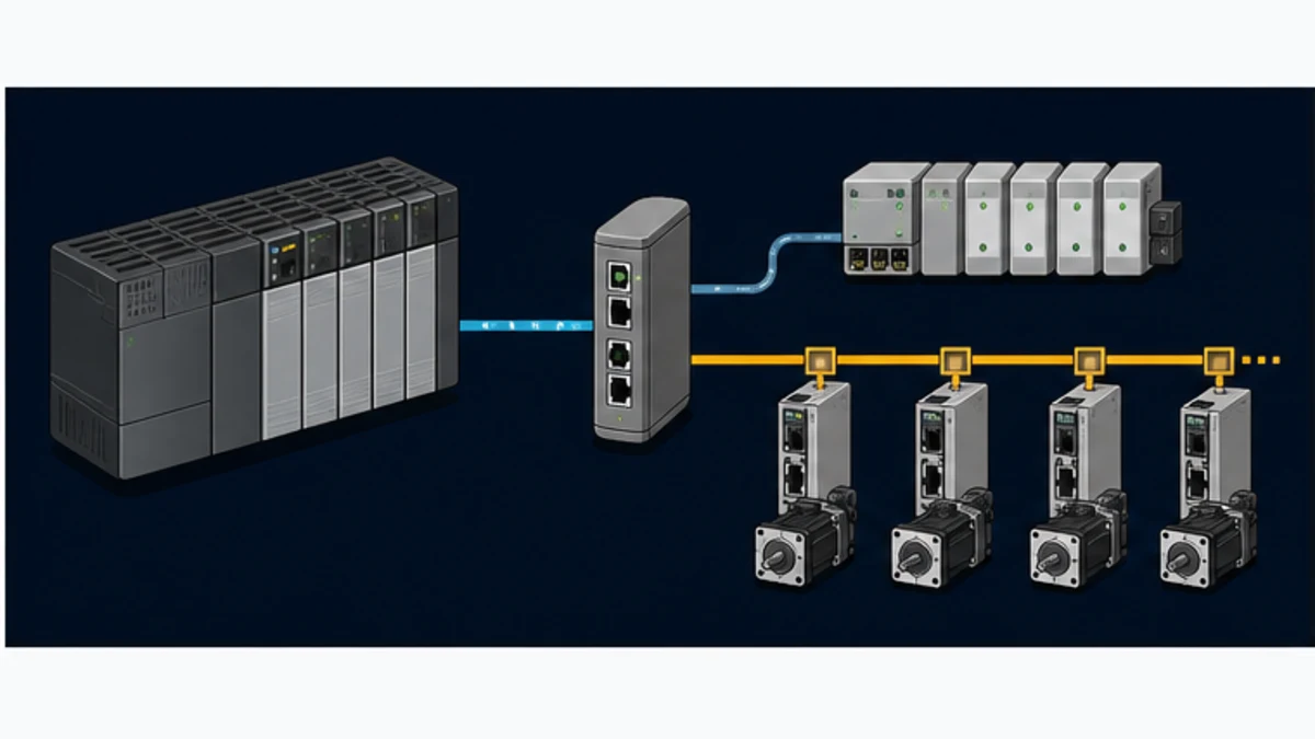
This page owns the Allen-Bradley and Rockwell Logix gateway-selection, Studio 5000 mapping, commissioning and cross-network troubleshooting task. Use the EtherCAT PLC guide for protocol-wide state-machine, frame, PDO, mailbox, Working Counter and Distributed Clocks fundamentals. Use the EtherNet/IP PLC guide for CIP connections, assemblies, RPI, multicast and DLR fundamentals. Keeping those parent subjects separate avoids duplicating broad protocol explanations or implying native compatibility.
Establish the capability from exact part numbers
Similar Ethernet media does not create protocol compatibility
EtherNet/IP and EtherCAT can both operate over familiar Ethernet physical media, yet their controller roles, frame behavior, discovery, configuration artifacts and timing models are different. EtherNet/IP adapts the Common Industrial Protocol, or CIP, to Ethernet and IP transports. ODVA describes Adapter and Scanner device classes, explicit messaging and implicit cyclic I/O connections. EtherCAT uses one MainDevice to organize a segment while SubDevices process assigned data in passing frames. An unmanaged switch, patch lead or IP address cannot translate those application protocols.
Begin with the exact catalog numbers rather than the broad words “Allen-Bradley PLC.” Record the controller family, controller catalog number, firmware revision, communication module catalog number, Studio 5000 Logix Designer version and installed Add-On Profiles. Open current Rockwell documentation for those exact products and list their supported networks and roles. If EtherCAT is not named as a supported MainDevice function, the project needs a documented external gateway, an approved specialist module, or a separate EtherCAT controller.
| Verification question | Retained evidence | Stop condition |
|---|---|---|
| Which Logix platform is installed? | complete controller and communication-module catalog numbers, series and firmware | only “ControlLogix” or “CompactLogix” is known |
| What role does the Logix-facing port provide? | manual naming EtherNet/IP Scanner/originator capability and supported connection types | role is inferred from an RJ45 socket or a product logo |
| What does the field equipment require? | manuals naming EtherCAT MainDevice/SubDevice roles, PDOs, profiles and synchronization modes | device is described only as “industrial Ethernet” |
| Who owns the EtherCAT line? | signed architecture identifying the MainDevice and every boundary | team cannot name the MainDevice |
| What must cross the gateway? | versioned byte contract with directions, types, age and invalid behavior | requirement says “share all tags” |
| Which functions are excluded? | written boundary for motion, safety, configuration, diagnostics and security | bridge is assumed to translate every service |
Check native alternatives before adding a gateway
Many drives, I/O platforms and robot interfaces are offered with different network options. If the same field product has an approved EtherNet/IP Adapter interface, connecting it directly to a supported Logix EtherNet/IP network usually removes a configuration tool, protocol boundary, latency source, spare part and diagnostic layer. This is not always possible on an installed machine or a vendor-owned EtherCAT subsystem, but it belongs in the design review.
Do not confuse “direct” with “automatically suitable.” A native EtherNet/IP device still needs its EDS or AOP, supported firmware, connection sizes, requested packet interval, ownership, network capacity and application behavior verified. The comparison simply asks whether the EtherCAT requirement is fundamental or incidental.
| Architecture | Best fit | Main advantage | Material limitation |
|---|---|---|---|
| native EtherNet/IP field option | selectable device interface and Logix owns control | one native engineering and diagnostic path | may not exist or may conflict with an established EtherCAT machine standard |
| EtherNet/IP-Adapter/EtherCAT-MainDevice gateway | Logix must control bounded ordinary I/O on EtherCAT SubDevices | supplies the missing EtherCAT initiating role | adds tools, mappings, latency, capacity limits and a failure domain |
| EtherNet/IP-Adapter/EtherCAT-SubDevice coupler | two existing controllers exchange machine data | creates a clear controller-to-controller contract | does not control the EtherCAT SubDevice line |
| separate native EtherCAT motion controller | EtherCAT timing and motion remain tightly coupled | preserves a qualified EtherCAT motion domain | requires supervisory command/status integration with Logix |
| supported in-chassis specialist module | exact module is documented for the target chassis and EtherCAT role | may integrate status and data more closely with Logix | vendor-specific lifecycle, capacity, profile and support constraints still apply |
Select the architecture by both port roles
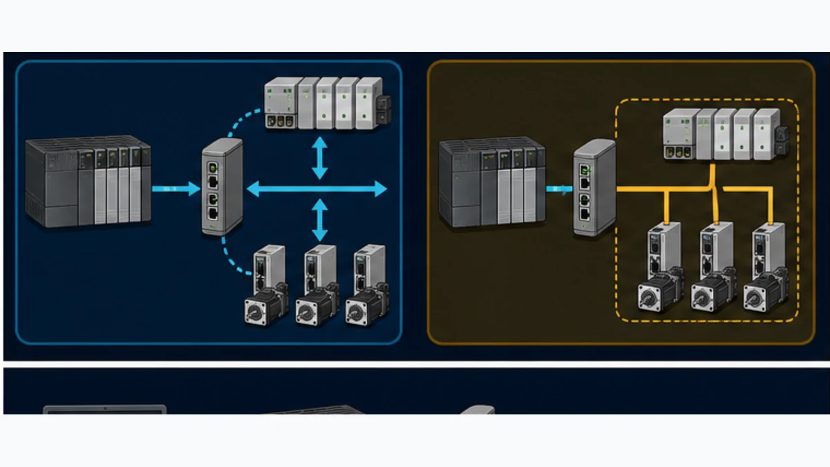
Pattern A: Logix owns ordinary EtherCAT I/O through a MainDevice gateway
In this pattern, Logix opens an EtherNet/IP implicit I/O connection to the gateway. Logix is the Scanner/originator; the gateway is the Adapter/target. On its isolated field-facing port, the same gateway is the EtherCAT MainDevice. It loads the EtherCAT topology, identifies SubDevices, advances their state machines, schedules frames, handles Working Counter expectations and maps selected PDO data into its EtherNet/IP assemblies.
The purchase description must say more than “EtherNet/IP to EtherCAT.” Confirm the exact simultaneous personality, primary and secondary port roles, firmware package, licenses, maximum assembly bytes, maximum EtherCAT SubDevices, minimum supported cycle, process-data mapping limits, mailbox services, drive-profile support, Distributed Clocks modes, hot-connect behavior, configuration tool and diagnostics. A vendor family may list both protocols while a particular firmware image supports the opposite role pair.
Hilscher's NT 151-RE-RE datasheet lists protocol combinations using abbreviations such as EIS/ECM: EtherNet/IP Slave/Adapter on one network and EtherCAT Master/MainDevice on the other. Its architecture uses separate network controllers and an internal data buffer. That is the role combination needed for basic Logix-owned EtherCAT I/O. The supplier's published gateway processing below 10 ms is a device-level product claim, not the complete command-to-feedback age, and must not be copied into a machine requirement without measurement.
Pattern B: Logix exchanges data with an existing EtherCAT machine
Here, a separate controller already owns the EtherCAT line. The bridge is an EtherNet/IP Adapter toward Logix and an EtherCAT SubDevice toward the machine controller. Each controller sees one ordinary I/O device on its own network. The bridge copies a deliberate request/status interface between those images.
This is usually the cleaner pattern for vendor machines, skids and cells. Logix can request modes, send recipes or line-speed references, receive ready/running/fault states and monitor production counters without taking responsibility for internal EtherCAT drives or remote I/O. The EtherCAT machine controller keeps its native cycle, Distributed Clocks configuration, drive state machines and diagnostic ownership.
Pattern C: a native EtherCAT controller owns synchronized motion
Use a native, vendor-supported EtherCAT motion controller or approved platform when coordinated servo axes, registration, camming or precise phase relationships are central to the machine. Logix can remain the cell or line controller and exchange supervisory data through a documented peer interface. Keep fast position loops, synchronized triggers and drive-profile sequencing inside the native motion domain.
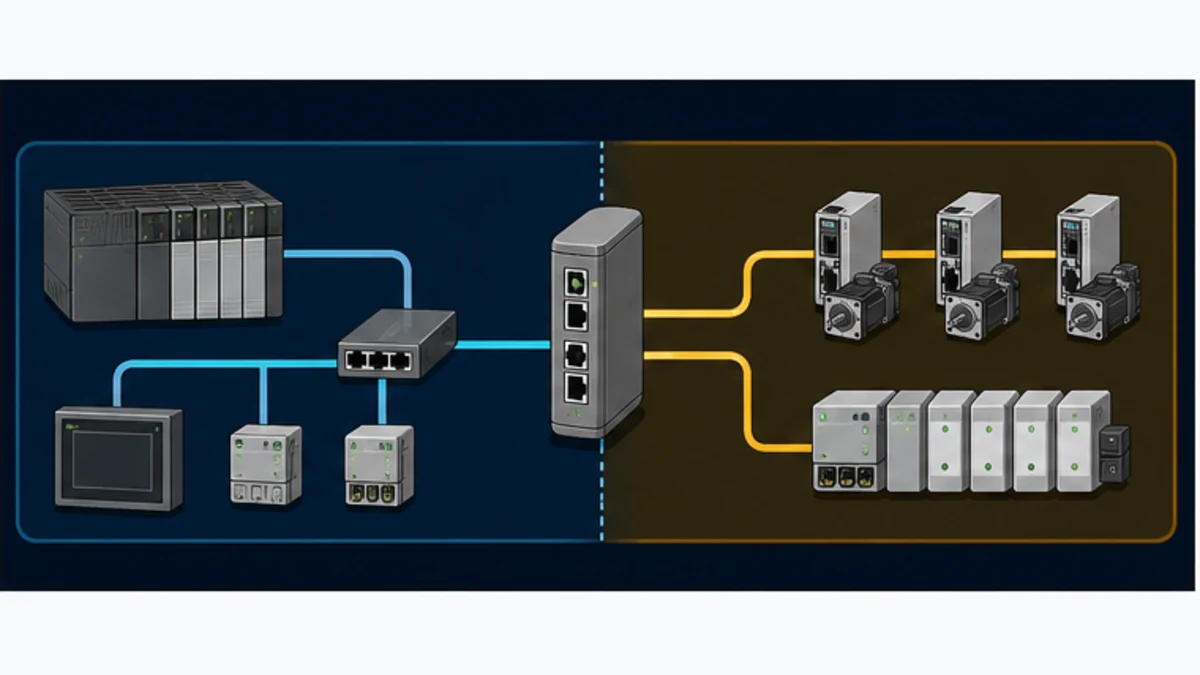
| Required result | Logix-facing role | EtherCAT-facing role | Appropriate pattern |
|---|---|---|---|
| ControlLogix reads and writes ordinary EtherCAT I/O | EtherNet/IP Adapter | EtherCAT MainDevice | active dual-network gateway |
| CompactLogix exchanges commands with a vendor machine | EtherNet/IP Adapter | EtherCAT SubDevice | controller-to-controller coupler or dual-device gateway |
| EtherCAT controller supervises a Logix subsystem | role depends on approved peer architecture; often Adapter at Logix boundary | EtherCAT SubDevice | bounded machine interface, not field-I/O ownership |
| multiple EtherCAT axes require precise coordination | supervisory EtherNet/IP or another approved peer interface | native EtherCAT MainDevice belongs to motion controller | hierarchical control architecture |
| field device offers a supported EtherNet/IP option | native Adapter in the field device | no EtherCAT bridge | direct EtherNet/IP architecture |
Reject names that omit direction
“EtherCAT/EtherNet/IP converter,” “two-port gateway” and “multi-protocol bridge” are discovery phrases, not specifications. The product may be an EtherNet/IP Scanner to EtherCAT SubDevice—the reverse of the common Logix requirement. It may support both device roles, so neither side controls a field network. It may load only one stack at a time, omit EtherCAT Distributed Clocks or expose fewer bytes than the project needs. Put the complete role pair and simultaneous-operation requirement on the quotation request.
Freeze the interface contract before Studio 5000 configuration
A useful gateway map carries meaning and health
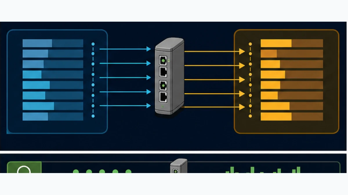
Define the smallest interface that lets each controller remain internally independent. Typical Logix outputs are request bits, a command sequence, interface version, recipe number, mode request and bounded setpoints. Typical Logix inputs are accepted sequence, ready/running/complete states, interface version, diagnostic summary, data-valid state, heartbeat and bounded actual values. Avoid mirroring controller-scoped tags or hundreds of internal bits.
For every field, record producer, consumer, byte and bit offset, CIP assembly direction, EtherCAT PDO direction, primitive type, byte order, sign, scaling, engineering unit, valid range, update expectation, invalid marker, startup value and response when stale. “Input” is viewpoint-dependent: an EtherNet/IP Input Assembly is produced by the Adapter and consumed by Logix, while an EtherCAT input PDO is produced toward the MainDevice. Use producer and consumer names in the contract to remove that ambiguity.
| Offset | Logix tag | Logix view | Type | Contract rule |
|---|---|---|---|---|
0.0 |
EC_RequestRun |
output to gateway | BOOL | request only; remote permissives and safety still govern action |
0.1 |
EC_ResetRequest |
output to gateway | BOOL pulse | edge or sequence behavior is explicit; never a permanently asserted reset |
2 |
EC_CommandSequence |
output to gateway | UINT | increments for every new command set; rollover behavior is tested |
4 |
EC_CommandHeartbeat |
output to gateway | UINT | changes at a defined application interval while the producing task is healthy |
6 |
EC_LocalContractVersion |
output to gateway | UINT | command acceptance requires the approved compatible version |
8 |
EC_SpeedDemand_x10 |
output to gateway | INT | signed, bounded value with 0.1 engineering-unit scaling |
16.0 |
EC_RemoteReady |
input to Logix | BOOL | application readiness, not a functional-safety claim |
16.1 |
EC_RemoteRunning |
input to Logix | BOOL | backed by documented feedback, not command echo alone |
18 |
EC_AcceptedSequence |
input to Logix | UINT | identifies which command set the remote application accepted |
20 |
EC_StatusHeartbeat |
input to Logix | UINT | remote application freshness source independent of link state |
22 |
EC_InterfaceFault |
input to Logix | WORD | versioned interface diagnostic enumeration |
24 |
EC_ActualSpeed_x10 |
input to Logix | INT | value is usable only when validity, version and age tests pass |
Protect multi-byte values and revisions
Choose one byte order at the gateway boundary and verify it with non-symmetric patterns such as hexadecimal 12 34 56 78, positive and negative integers, minimum/maximum scale values and a known IEEE-754 floating-point value if REAL data is unavoidable. Do not assume that a DINT array in Logix, an assembly byte stream, a gateway word map and an EtherCAT PDO structure share alignment or byte order.
Group a coherent command set with a sequence. The producer writes values, version and control bits, then changes the sequence. The consumer copies the received block, confirms a stable sequence, validates every range and acknowledges the accepted sequence. This prevents a consumer from acting on a partially updated multi-field command if the two networks and application tasks are not phase-aligned.
| Contract element | Purpose | Fault prevented |
|---|---|---|
| interface version | blocks silent use of incompatible maps | one side downloads a new field layout while the other stays old |
| command sequence | identifies a coherent request set | consumer mixes fields from two producer updates |
| accepted sequence | proves remote application—not only the gateway—processed a command | Logix mistakes transport for execution |
| heartbeat and calculated age | detects a frozen producer while network links remain up | stale values look valid indefinitely |
| data-valid and quality summary | distinguishes usable process data from copied bytes | healthy EtherNet/IP connection masks an EtherCAT or device fault |
| bounded values and invalid markers | catches scale, endian and sensor failures | absurd numbers reach machine logic |
| first-fault code and timestamp | preserves the initiating boundary through cascades | later connection alarms erase the original cause |
| restart handshake | requires fresh intent after recovery | restored communication restarts equipment unexpectedly |
Use a dedicated Logix interface layer
Keep raw module-defined or generic-module tags inside one Add-On Instruction, program or routine owned by the interface. The outbound routine sanitizes and packs application commands. The inbound routine copies raw bytes, unpacks types, checks version, range, quality and age, and publishes a typed user-defined structure. Machine logic consumes EtherCATCell.Status.Ready, not scattered Gateway:I.Data[17].3 references.
A vendor-neutral Structured Text pattern can express the intent without pretending to be drop-in code:
HeartbeatChanged := EC_StatusHeartbeat <> LastStatusHeartbeat;

IF HeartbeatChanged THEN
    LastStatusHeartbeat := EC_StatusHeartbeat;
    StatusAge_ms := 0;
ELSE
    StatusAge_ms := StatusAge_ms + InterfaceTaskPeriod_ms;
END_IF;

ContractOK := EC_RemoteContractVersion = ExpectedContractVersion;
Fresh := StatusAge_ms <= MaximumStatusAge_ms;
TransportOK := GatewayModuleHealthy AND EtherNetIPConnectionHealthy;
RemoteNetworkOK := EC_EtherCATOperational AND EC_DataValid;

InterfaceHealthy := TransportOK AND RemoteNetworkOK AND ContractOK AND Fresh;

IF NOT InterfaceHealthy THEN
    EC_RequestRun := FALSE;
    PublishedStatus.Valid := FALSE;
END_IF;
Run Structured Text in the simulator
The actual Logix instructions, timers, connection-status members and data-copy method depend on controller firmware, profile and project standards. The important design is the separation of transport health, remote-network health, contract compatibility, freshness and application validity.
Live mini-lab
Try it: press START, then STOP
A stop-dominant seal-in rung: START latches the motor output through its own contact, and STOP breaks the circuit.
Watch the output lamp: it stays on after START until you press STOP.
Free to start · runs in your browserOpens plcsimulationsoftware.com — same team
Configure the EtherNet/IP side in Studio 5000
Prefer the exact supported profile
Obtain the gateway manufacturer's current EDS, Add-On Profile or Studio 5000 integration instructions for the exact firmware personality. An EDS describes EtherNet/IP identity and communication capabilities; an AOP can provide a richer device-specific configuration experience. Neither configures the EtherCAT topology behind an active gateway. Preserve the source URL, version and checksum with the project.
If a supported AOP is supplied, add the exact catalog object beneath the correct controller or EtherNet/IP bridge in the I/O Configuration tree. Set the approved IP address or host identity, profile revision, connection and RPI. If only a generic Ethernet module is supported, enter the Input, Output and Configuration Assembly instances, sizes and data format exactly as the gateway manual specifies. Rockwell documentation shows that generic modules create controller tags from those assembly settings; a wrong instance, byte/word unit or size can keep the connection faulted or silently shift the interpretation.
Do not guess 100/101/1 because another device uses those common-looking numbers. Assembly instances are product-defined. Confirm whether sizes are entered as SINTs, INTs or DINTs for the chosen communications format and software version. Confirm whether run/idle headers are handled automatically. Record connection type, unicast/multicast choice, requested packet interval, timeout behavior and ownership requirements.
| Studio 5000 item | Acceptance evidence | Frequent defect |
|---|---|---|
| product integration | exact EDS/AOP or documented generic-module procedure matches firmware | nearest catalog entry selected because the name looks similar |
| assembly instances | supplier table identifies Input, Output and Configuration instances | instances copied from a forum or another firmware personality |
| data sizes and format | byte totals match gateway configuration in both directions | 16 means words on one side and bytes on the other |
| RPI | supported by controller, network and gateway; included in measured age budget | RPI minimized without capacity or task analysis |
| electronic keying | project standard and vendor guidance are documented | keying disabled to hide a product/revision mismatch |
| module inhibit/startup | commissioning sequence prevents unexpected use of stale outputs | connection establishes before contract and readiness checks exist |
| diagnostics | connection fault, module status and first failure are exposed to interface logic | only the I/O tree icon is checked during commissioning |
Engineer the RPI instead of selecting the smallest value
The requested packet interval controls how frequently the EtherNet/IP implicit I/O connection requests updates; it is not the complete application response time. A very small RPI can consume controller and network connection resources without improving a gateway whose internal or EtherCAT cycle is slower. A very large RPI can dominate the age budget and stale-data detection. Begin with the application requirement and documented device limits, then measure under representative controller and network load.
Keep management and explicit-message activity out of the critical commissioning window where possible. Diagnostic web traffic, parameter reads, produced/consumed tags and other I/O connections share controller, module, switch and gateway resources. Capture utilization and connection statistics when the production configuration is active, not only on an empty bench.
Configure the EtherCAT side with the exact ESI set
Active gateway configuration
Use the gateway vendor's supported configuration tool and manual. Load the firmware personality that provides EtherNet/IP Adapter and EtherCAT MainDevice simultaneously. Import the exact EtherCAT SubDevice Information, or ESI, XML for every installed device and revision. Build the physical order, choose PDO mappings, configure necessary mailbox startup parameters, select a defensible EtherCAT cycle and enable Distributed Clocks only where the gateway and devices support the intended mode.
ETG describes ESI as the XML representation of a SubDevice's network-accessible properties, process-data mapping options, mailbox protocols and synchronization modes. Match vendor ID, product code and revision rather than choosing a visually similar device. An online scan that finds an “unknown” or revision-mismatched unit is evidence to stop and obtain the correct description, not permission to force the nearest XML.
For ordinary I/O, prove state progression through INIT, PREOP, SAFEOP and OP as applicable, expected versus actual Working Counter, PDO direction and watchdog response. For drives, additionally prove the exact application profile, control/status word transitions, supported operation modes, scaling and fault reset. A gateway that can transport drive PDOs is not necessarily a qualified multi-axis motion controller.
Existing EtherCAT controller configuration
For the coupler pattern, the machine's EtherCAT engineering tool imports the bridge ESI and adds it as a SubDevice. The EtherCAT controller remains responsible for topology, cycle, PDO selection, state transitions and diagnostics. Compare its selected RxPDO/TxPDO lengths with the gateway's EtherNet/IP Output/Input assembly lengths field by field. Maintain one signed interface revision across both controller projects.
| Evidence | Active MainDevice gateway | Existing-controller coupler |
|---|---|---|
| EtherCAT owner | gateway | separate machine or motion controller |
| description files | ESI for every downstream SubDevice | ESI for the bridge/coupler in the existing controller project |
| topology | gateway project owns exact order and branches | existing EtherCAT project owns bridge position and identity |
| PDO map | gateway maps SubDevice PDOs to EtherNet/IP assemblies | bridge PDOs mirror the bounded Logix assembly contract |
| state diagnostics | gateway reports line and device AL states, WKC and port evidence | existing controller reports bridge state and network evidence |
| timing | gateway EtherCAT cycle joins Logix task/RPI in age budget | two controller tasks/cycles plus bridge transfer join age budget |
| restoration | gateway personality, project, ESI set and Logix configuration are restored | both controller projects and shared contract revision are restored |
Build and measure an end-to-end timing budget
Multiple cycles create phase-dependent age
End-to-end age is not simply the EtherNet/IP RPI plus the EtherCAT cycle. A command may wait for the Logix task, the next EtherNet/IP production opportunity, the gateway copy task, the next EtherCAT frame and the remote application task. Feedback travels through another series of boundaries. If independently scheduled cycles align badly, an occasional update can take materially longer than the typical value.
Create typical, worst-observed and maximum-allowed budgets for both directions. Toggle a sequence value at the producing application boundary and trace when the consuming application accepts it. Run the test under representative I/O connection count, controller task load, switch traffic, complete EtherCAT topology and diagnostic activity. Repeat across power-up, cable restoration and device-recovery conditions.
| Timing component | Configuration evidence | Measurement evidence |
|---|---|---|
| Logix producing task | period, priority, overlap and watchdog | task monitor or trace shows actual release and completion behavior |
| EtherNet/IP connection | RPI, connection type, timeout and module path | sequence transition is observed at gateway-facing data boundary |
| gateway processing | supplier documentation and firmware-specific settings | controlled input-to-output propagation distribution under load |
| EtherCAT cycle | cycle, synchronization mode, topology and watchdog | MainDevice statistics and trace/capture where supported |
| remote application | task that consumes/produces mapped PDO data | accepted sequence and response transition in controller trace |
| maximum data age | requirement tied to machine behavior | injected delay/loss causes rejection before hazardous or invalid use |
Hilscher advertises gateway data processing below 10 ms for the NT 151 family. Even when representative hardware confirms that claim, total age still includes the producer task, RPI, EtherCAT schedule, remote task and phase. Quote the measured end-to-end distribution for the exact project instead of turning a component claim into a system guarantee.
Preserve native timing for motion
EtherCAT Distributed Clocks synchronize supported SubDevices to an EtherCAT reference-clock domain. CIP Motion and CIP Sync are different services with their own products, timing model and validation. A general assembly/PDO gateway does not automatically translate CIP Motion objects into an EtherCAT drive profile or merge the two clock domains. It may carry a speed reference adequately for a slow independent axis while being unsuitable for coordinated position control.
Classify every exchanged value. Supervisory recipes, mode requests, production counts and line-speed references often tolerate a measured bridge. Coordinated cam positions, registration events, torque loops, synchronized capture and safe motion require a vendor-approved deterministic architecture. Put those exclusions in the specification before the gateway is purchased.
Commission one boundary at a time
Prepare a reversible test state
Archive the Logix project, gateway firmware and configuration, EtherCAT project or ESI set, switch configuration and device parameter backups. Record checksums, versions, serial numbers and a rollback owner. Commission with field energy removed or the machine in an approved controlled test state. The first successful bit transfer must not be a real actuator command.
- Verify controller, EtherNet/IP module, gateway and EtherCAT device catalog numbers, series and firmware against the approved design.
- Inspect power, functional earth, shielding, port labels and physical segregation using each manufacturer's installation instructions.
- Connect the EtherNet/IP side only; assign the approved IP configuration and prove exact gateway identity and Logix module connection.
- Confirm Input, Output and Configuration Assembly instances, format and byte sizes against the gateway project.
- For an active gateway, attach one known EtherCAT SubDevice and prove identity, order, state and PDO mapping before adding the complete line.
- For an existing EtherCAT controller, prove the bridge SubDevice in that project and compare both image definitions.
- With commands inhibited, toggle one bit and one non-symmetric multi-byte pattern in each direction; retain screenshots or exports at every boundary.
- Test sign, scaling, extremes, invalid markers, heartbeat stop, sequence rollover and contract-version mismatch.
- Remove EtherNet/IP and EtherCAT links independently; verify first-fault capture, invalidation, command inhibition and defined local behavior.
- Restore each failure; require deliberate resynchronization and prove that communication return alone cannot restart hazardous motion.
- Repeat timing and loss tests under representative controller, network, gateway and EtherCAT load.
- Complete the approved functional, cybersecurity and functional-safety validation before production release.
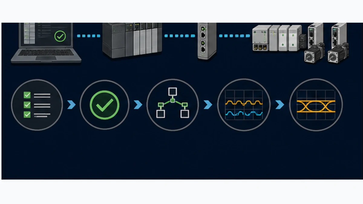
| Acceptance test | Controlled stimulus | Expected Logix evidence | Expected gateway or EtherCAT evidence |
|---|---|---|---|
| EtherNet/IP loss | disconnect the approved Logix-facing test link | module/connection fault, interface invalid, commands inhibited, first timestamp retained | EtherCAT side follows documented independent-loss policy |
| EtherCAT first-link loss | disconnect field-facing link in controlled state | gateway may remain connected, but remote-network health and data-valid fail | state/WKC/visible-device evidence identifies EtherCAT boundary |
| downstream node loss | remove power or link at a known topology position | affected data rejected; recovery cannot restart automatically | first missing position and port counters localize fault |
| frozen application | stop heartbeat changes while both transports remain operational | age timer expires and fallback is applied | green network status demonstrates why application freshness is separate |
| map mismatch | load an intentionally incompatible lab contract revision | version check blocks requests and identifies mismatch | raw transport may remain healthy, separating data from meaning |
| recovery | restore exact baseline, then acknowledge | health rebuilds in defined sequence; fresh intent is required | both protocol states recover without unapproved remapping |
Diagnostic answer map: diagnose the first failed layer
Capture four simultaneous views
Retain the Logix I/O-tree/module and controller diagnostics, the gateway's EtherNet/IP and system diagnostics, the EtherCAT MainDevice topology/state view, and the application contract view. A green Logix module connection proves only the Logix-facing transport. The gateway can remain a healthy EtherNet/IP Adapter while its EtherCAT network is in PREOP, missing a SubDevice or producing invalid data.
On EtherCAT, compare expected and actual Working Counter, required AL state, visible device count/order, identity/revision and per-port error or lost-link evidence. A Working Counter mismatch indicates that the expected number of memory operations was not completed; it is a strong digital symptom, not a unique diagnosis. Combine it with topology and physical evidence before replacing hardware. On EtherNet/IP, inspect module fault details, connection timeouts, identity/keying, assemblies, sizes, RPI and path before changing ladder logic.
| Symptom | First discriminating evidence | Likely boundary | Next controlled check |
|---|---|---|---|
| gateway missing from I/O tree online state | ping alone is insufficient; inspect module path, identity, keying and connection fault | EtherNet/IP identity/configuration | confirm exact IP, profile, product revision and route |
| module connection faults immediately | assembly instances, data format and configured sizes | EtherNet/IP application connection | compare every value with firmware-specific gateway manual |
| EtherNet/IP healthy but all process data invalid | gateway remote-network status and EtherCAT state | gateway personality or EtherCAT configuration | verify active role pair, ESI set, device count/order and required OP state |
| EtherCAT stops in SAFEOP | AL status, PDO assignment, watchdog and DC mode | EtherCAT application configuration | match exact device revision, SyncManager/PDO lengths and startup parameters |
| intermittent WKC mismatch | expected/actual WKC plus port error and lost-link counters | EtherCAT physical/device/timing | localize first affected topology position; inspect power, cable, shielding and port |
| raw bytes move but values are wrong | known hex pattern at Logix assembly, gateway map and PDO | representation contract | verify direction, offset, byte order, alignment, sign and scale |
| values freeze with both networks green | application heartbeat age and accepted sequence | producer task or gateway copy | identify which boundary stopped changing; retain first timestamp |
| motion is rough only under load | end-to-end age/jitter trace and native drive diagnostics | architecture/timing | move tight loop to approved native controller or prove vendor-supported limits |
| equipment restarts after cable restoration | latched request, accepted sequence and startup inhibit | recovery logic | require fresh command, remote ready and deliberate acknowledgement |
Separate identity, state, bytes and semantics
Ask the diagnostic questions in a fixed order. Does the expected product answer with the exact identity? Did the EtherNet/IP connection and required EtherCAT states establish? Do known bytes move in each direction at the documented offsets? Are the values compatible, fresh, in range and meaningful to the receiving application? Did the machine behave correctly through normal, loss and recovery cases? Each answer narrows the failed layer.
Do not clear, power-cycle or download before retaining the first evidence unless safety requires it. A restart may erase an AL status, module fault, port counter sequence or first-out application code. Capture controller time, gateway time and EtherCAT controller time—or document their offsets—so events can be ordered later.
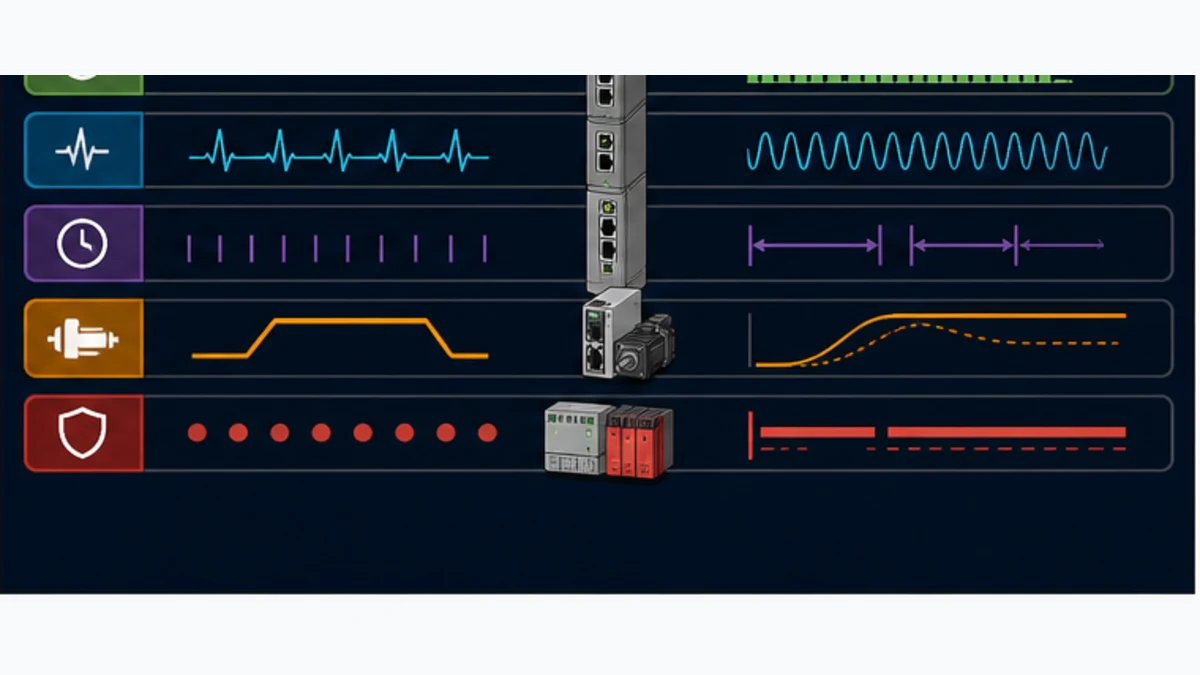
| Layer | Positive proof | Misleading shortcut |
|---|---|---|
| physical | correct port, power, cable, bonding and stable counters under representative operation | link lights prove application communication |
| identity | exact CIP identity/keying and exact EtherCAT vendor/product/revision/order | a similar profile or ESI entry is close enough |
| protocol state | Logix I/O connection established; required EtherCAT states and expected WKC sustained | gateway web page is reachable |
| byte transport | known patterns arrive in both directions at reviewed offsets | nonzero data means the mapping is correct |
| contract | version, sequence, age, quality, range and scale pass | most process values look plausible |
| machine behavior | normal, loss, overload, recovery and restart tests meet specification | one successful cycle proves production readiness |
| functional safety | approved architecture, components, calculations, validation and proof tests meet the safety requirement | ordinary watchdog or mapped permit is credited with PL or SIL |
Bound motion, safety, cybersecurity and availability claims
Ordinary EtherNet/IP assemblies and EtherCAT PDOs transferred by a general gateway are not a functional-safety channel. A watchdog, heartbeat or data-valid bit can improve standard-control fault response, but it does not create CIP Safety, Safety over EtherCAT/FSoE, Performance Level or Safety Integrity Level. Do not assume that a gateway translates CIP Safety and FSoE. Keep guards, emergency stops, STO and other risk-reduction functions in the approved safety architecture unless an exact certified product and validated design explicitly provide otherwise.
For each communication loss, define the local responsible controller, ordinary output behavior, invalid-data behavior, alarm, reset and restart rule. Holding a displayed temperature may be acceptable while holding a speed command may not be. “Set outputs to zero” can also be wrong where controlled deceleration or a maintained utility is required. The machine risk assessment and functional specification determine the response; a generic gateway default does not.
The bridge adds configuration software, firmware, credentials, management services and backup files. Place each management interface in the approved industrial zone, use unique credentials where supported, restrict services and remote paths, record configuration hashes, monitor vendor advisories and test restoration onto a spare. Do not route general enterprise traffic through the field-facing EtherCAT port. EtherCAT's physical use of Ethernet does not make that port an ordinary plant LAN connection.
| Governance control | Required evidence | Release blocker |
|---|---|---|
| safety boundary | hazard-specific safe response and independent approved safety function | mapped ordinary bit is treated as safety-rated permission |
| motion boundary | documented ownership of every fast loop and timing domain | general gateway is assumed to translate synchronized motion |
| access control | named owners, approved management path and credential handling | shared default credentials or unnecessary remote exposure |
| configuration control | versioned controller, gateway, ESI and interface files with checksums | replacement depends on an undocumented engineering laptop |
| monitoring | connection, EtherCAT state, freshness, first fault and time-aligned logs | one common alarm hides the side that failed |
| lifecycle | supported firmware, spare, restore drill and vendor advisory process | gateway is an untested single point of failure |
Procurement and design-review checklist
Attach a role-and-acceptance schedule to the quotation. Name the exact ControlLogix or CompactLogix controller, communications path, Studio 5000 version, required EtherNet/IP Adapter behavior, required EtherCAT MainDevice or SubDevice behavior, SubDevice list, assembly and PDO bytes, profile/mailbox needs, cycle and maximum data-age requirement, environmental rating, power, isolation, diagnostic access, configuration license, cybersecurity expectations, certifications and spare strategy.
Require the supplier to identify the precise order number, firmware personality and simultaneous protocol combination. Ask for current manuals, EDS/AOP, ESI where applicable, configuration software and license terms before purchase. If a motion claim matters, obtain a written statement of supported drive profiles, modes, DC behavior and measured limitations. Then run a representative-hardware acceptance test; do not accept a protocol-logo matrix as the final proof.
| Design gate | Go evidence | Hold evidence |
|---|---|---|
| ownership | every port is labelled Scanner/Adapter or MainDevice/SubDevice | arrows only say Ethernet or data |
| product fit | supplier confirms exact simultaneous role pair, firmware and tools | both protocol logos appear but roles are omitted |
| mapping | signed assembly/PDO contract includes version, age, quality and recovery | spreadsheet contains only offsets and tag names |
| capacity | bytes, connections, devices and features fit documented limits with margin | diagnostic and future fields were not counted |
| performance | representative worst-case data age and jitter meet requirement | component cycle values were merely added |
| diagnostics | team can isolate Logix, gateway, EtherCAT position and application faults | one gateway-ready bit is the only evidence |
| restoration | spare replacement and complete configuration restore are demonstrated | files, license or firmware cannot be reproduced |
| safety/security | responsible reviewers approve explicit boundaries and controls | gateway is credited with undocumented safety or security behavior |
Worked architecture decisions
Remote EtherCAT I/O with slow machine sequencing
A CompactLogix machine needs several digital and analog points from an existing EtherCAT terminal line. No coordinated motion crosses the bridge, and a measured tens-of-milliseconds age satisfies the control specification. The defensible candidate is an EtherNet/IP-Adapter/EtherCAT-MainDevice gateway. Map only required I/O plus network state, data validity, heartbeat, version and diagnostic summary. Validate terminal ESI revisions, analog scaling, loss response and end-to-end age. A native EtherNet/IP I/O alternative should still be costed because it may reduce lifecycle risk.
Vendor machine with an internal EtherCAT controller
A ControlLogix line controller must start a packaging machine, select a recipe and receive ready, running, complete, fault and count data. The packaging machine already has a native EtherCAT controller. Use an EtherNet/IP-Adapter/EtherCAT-SubDevice coupler or another vendor-approved controller interface. Keep axis commands and EtherCAT diagnostics in the packaging controller; expose a versioned machine contract and enough summary evidence for line-level diagnosis. This avoids creating two MainDevices for one EtherCAT segment.
Multi-axis machine requiring sub-cycle synchronization
A cell specification calls for synchronized capture and coordinated axes on EtherCAT drives while ControlLogix manages upstream material handling. A general gateway should carry supervisory mode, recipe, line-speed reference, readiness and production data only. The native EtherCAT motion controller owns the servo loop, Distributed Clocks, drive profile and axis faults. The integration acceptance test measures supervisory age and proves that loss on either side produces the approved state without representing the gateway as a synchronized-motion translator.
Retrofit with an ambiguous gateway already purchased
The label lists EtherNet/IP and EtherCAT but the EtherCAT I/O line never reaches OP. Before changing mappings, find the firmware personality and port-role table. If the unit is EtherNet/IP Adapter plus EtherCAT SubDevice, it expects controllers on both sides and cannot own the I/O line. The remedy is an approved MainDevice personality/product, a separate EtherCAT controller or a native EtherNet/IP field redesign—not more Studio 5000 tags.
Frequently asked questions
Do Allen-Bradley ControlLogix controllers support EtherCAT natively?
Current Rockwell Automation ControlLogix product and network documentation centers the integrated industrial Ethernet capability on EtherNet/IP and does not document the ordinary controller port as a general EtherCAT MainDevice. Verify the exact controller and any specialist communication module by catalog number and current manual. Without explicit EtherCAT role documentation, use a role-correct external gateway or separate EtherCAT controller.
Can I connect an EtherCAT drive directly to a CompactLogix Ethernet port?
Not merely with a cable. The controller port and drive option must implement the same protocol with complementary roles. If the drive has a supported EtherNet/IP Adapter option, use the Rockwell- and drive-vendor-approved direct integration. If it is EtherCAT-only, an approved EtherCAT MainDevice architecture is required.
Which gateway roles let Logix control EtherCAT I/O?
Logix normally acts as the EtherNet/IP Scanner/originator, so the gateway must be an EtherNet/IP Adapter toward Logix and an EtherCAT MainDevice toward the SubDevice line. Confirm those roles operate simultaneously in the exact firmware personality and verify capacity, profiles, cycle, diagnostics and licenses.
Is an EtherNet/IP-to-EtherCAT coupler always an EtherCAT MainDevice?
No. Some couplers are devices on both sides: EtherNet/IP Adapter and EtherCAT SubDevice. They exchange data between two existing controllers but cannot independently control a line of EtherCAT SubDevices. Product direction and role tables are more important than the converter's title.
What do EDS, AOP and ESI files configure?
An EDS describes EtherNet/IP device identity and capabilities, while an Add-On Profile can provide richer Studio 5000 integration. ESI describes an EtherCAT SubDevice to the EtherCAT configuration tool. None of them replaces the project-specific contract that defines the meaning, scale, version, freshness and loss response of mapped data.
How should a generic Ethernet module be configured in Studio 5000?
Use the gateway manufacturer's exact Input, Output and Configuration Assembly instances, data format and sizes for the installed firmware personality. Do not copy values from another product. Match the gateway byte totals, choose a justified RPI, expose connection status and prove both directions with known test patterns before enabling commands.
How can Logix detect stale EtherCAT data when the connection stays green?
Carry a changing heartbeat or sequence from the remote application, calculate its age in Logix, require a compatible contract version and carry explicit remote-network and data-valid states. Reject or substitute the data when any condition fails. Link and connection status alone cannot prove that the remote application is still updating meaningfully.
Can a gateway translate CIP Motion into EtherCAT synchronized motion?
Do not assume it can. A general process-image gateway does not automatically translate CIP Motion objects, EtherCAT drive profiles or the two timing domains. Keep tightly synchronized axes under a documented native motion controller or use an exact vendor-approved architecture validated on representative hardware.
What should I inspect when EtherNet/IP is healthy but EtherCAT data is bad?
Keep the healthy Logix-facing result and inspect the gateway's EtherCAT view: loaded personality, exact device count/order and identity, AL states, expected versus actual Working Counter, PDO lengths/directions, watchdog/DC configuration and port errors. Then compare raw patterns, byte order, scale, interface version and heartbeat age.
Does a gateway watchdog make ordinary mapped data safety rated?
No. Watchdogs, heartbeat bits and command inhibition improve standard-control diagnostics but do not create CIP Safety, FSoE, PL or SIL. Functional safety requires an approved safety requirements specification, architecture, components, calculations, validation and proof testing for the actual machine.
Practical next step
Write one of these role strings on the design before choosing hardware: Logix Scanner → gateway EtherNet/IP Adapter / EtherCAT MainDevice → SubDevices, or Logix Scanner → EtherNet/IP Adapter / EtherCAT SubDevice coupler → existing EtherCAT MainDevice. Freeze a small versioned map and ask the supplier to confirm the exact order number, firmware, roles, files, limits and representative acceptance test in writing.
Sources, review scope, and limitations
This guide was reviewed on August 30, 2026. Controller, profile, firmware, gateway personality, EtherCAT device and software capabilities change. These sources establish current documented concepts and product routes; only approved project documents and representative hardware prove a particular installation.
- Rockwell Automation, ControlLogix 5580 controller product page.
- Rockwell Automation, ControlLogix and GuardLogix technical documentation.
- Rockwell Automation, ControlLogix EtherNet/IP Network Devices User Manual, 1756-UM004.
- Rockwell Automation, EtherNet/IP Network Devices User Manual, ENET-UM006.
- Rockwell Automation, EtherNet/IP connected products and integration resources.
- Rockwell Automation, Logix 5000 Controllers I/O and Tag Data Programming Manual.
- ODVA, EtherNet/IP technology and CIP service overview.
- ODVA, EtherNet/IP Technology Overview, Publication 138.
- ODVA, current CIP network specification editions.
- ODVA, EtherNet/IP and CIP technical document library.
- Hilscher, netTAP NT 151-RE-RE product page and supported protocol roles.
- Hilscher, netTAP NT 151-RE-RE datasheet and firmware combinations.
- Hilscher, netTAP NT 151-RE-RE user manual.
- EtherCAT Technology Group, EtherCAT functional principle, MainDevice, ESI and Distributed Clocks.
- EtherCAT Technology Group, EtherCAT Compendium.
- EtherCAT Technology Group, ESI specification downloads and schema information.
- EtherCAT Technology Group, ETG.2200 EtherCAT SubDevice Implementation Guide.
- EtherCAT Technology Group, EtherCAT diagnosis for users.
- EtherCAT Technology Group, conformance guidance for device users and OEMs.
- EtherCAT Technology Group, official EtherCAT product guide.
Now run it · free to start
Follow plant data from sensor to SCADA
Fieldbus versus Ethernet, Modbus, EtherNet/IP, PROFINET, OPC UA and MQTT, then SCADA layers and alarms, taught on simulated equipment. Free to start.
Ownership disclosure: PLC Programming IO and PLC Simulation Software are operated by the same publisher.
PLC Programming IO Editorial Team
Industrial automation education, references, and software testing
The PLC Programming IO Editorial Team publishes sourced industrial-automation education and documents how material is reviewed, tested, and corrected. A team byline means the publisher is responsible for the page; it does not represent a fictional person or imply an engineering licence.
Coverage:
- • PLC programming concepts and examples
- • Vendor software tutorials and comparisons
- • SCADA, HMI, protocols, and instrumentation
- • Training, careers, and reference material
Review standard:
- • Prefer primary and official sources
- • Record software versions when material
- • Separate tested facts from estimates
- • Publish material corrections
Important scope note
This site provides education, not project-specific engineering approval. Safety, code, and compliance decisions require a qualified person with access to the actual machine and jurisdiction.