Beckhoff EtherCAT: TwinCAT 3 Setup, PDO Mapping and Diagnostics
Configure a Beckhoff PLC or IPC as an EtherCAT MainDevice in TwinCAT 3, map terminal PDOs to typed PLC data, commission Distributed Clocks where required, and diagnose state, Working Counter and CRC faults.
Review status: Editorially reviewed against current Beckhoff TwinCAT 3 I/O, EtherCAT System, EK1100, Tc2_EtherCAT, security and EtherCAT Technology Group documentation; the exact Beckhoff target, TwinCAT build/packages, operating system, real-time adapter, ESI, device identity/revision, terminal power, PDO/Startup configuration, task/DC timing, safety design and witnessed acceptance record govern each installation
Direct answer: configure the target, I/O chain and validity contract together
To configure EtherCAT on a Beckhoff PLC, Embedded PC or Industrial PC in TwinCAT 3, select the exact runtime target, bind an EtherCAT I/O device to a supported real-time Ethernet adapter or the target's documented EtherCAT interface, add or safely scan the physical SubDevice chain, compare it with the released topology, select the exact ESI and PDO variants, link I/O variables to typed PLC variables, assign the bus to the intended cyclic task, then activate and commission from a controlled safe state. Do not accept “the terminals are in OP” as the finish. Prove device identity, DevState, frame Working Counter state, per-device WcState, raw values, quality/status, output behavior, timing and recovery.
In current EtherCAT terminology, TwinCAT is the MainDevice that originates frames and configures the network. Beckhoff documentation and the TwinCAT user interface may still use “master” and “slave”; a field coupler or terminal is an EtherCAT SubDevice. An EK1100 is a SubDevice bus coupler between 100BASE-TX EtherCAT and the Beckhoff E-bus terminal row. It is not the MainDevice and it does not run the PLC application.
The working implementation chain is:
TwinCAT real-time task → EtherCAT MainDevice → supported interface → exact physical topology → SubDevice PDOs → TwinCAT process image → typed PLC interface → validated machine behavior
Every arrow is a test boundary. A link light proves a local physical link. A scan proves that TwinCAT discovered something. OP proves an EtherCAT state transition. None alone proves that the correct product, PDO variant, byte meaning, fresh value or machine response is present.
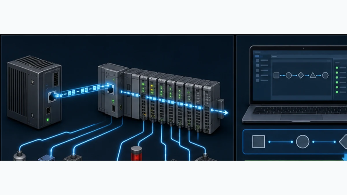
This page owns the Beckhoff/TwinCAT implementation task: target and adapter, discovery, ESI identity, PDO and Startup data, PLC linking, cyclic timing, commissioning, runtime health and fault isolation. The vendor-neutral EtherCAT PLC guide retains frame processing, cross-vendor selection, general topology and protocol fundamentals. The PLC communication troubleshooting guide retains the cross-protocol evidence ladder.
Understand the Beckhoff and EtherCAT roles before selecting hardware
Separate XAE engineering, XAR runtime and the EtherCAT interface
TwinCAT Engineering, commonly described as XAE, is where the project, I/O tree, mappings and PLC code are created. The real-time runtime, commonly described as XAR, executes on the selected target. They can be on the same computer, but a common production arrangement uses an engineering workstation connected to a remote CX or IPC target. The I/O configuration must describe the target that actually sends EtherCAT frames, not whichever laptop currently displays the project.
The runtime needs an interface that the exact Beckhoff target and installed TwinCAT environment support for EtherCAT real-time operation. On a PC target, the TwinCAT real-time Ethernet driver and the compatible-device list matter. On a CX controller, a built-in port may have a documented dedicated EtherCAT role. The presence of an RJ45 socket, an ordinary Windows network connection or successful IP traffic does not prove that a port is the approved real-time EtherCAT interface.
| Layer | Role in the released system | Evidence to freeze | Common mistake |
|---|---|---|---|
| engineering workstation | edits, compares, activates and troubleshoots the project | TwinCAT build/packages, project revision and authenticated user | treating the laptop's NIC as the production bus |
| TwinCAT runtime target | executes real-time tasks and PLC/motion application | target model, image/OS, runtime build, routes and licenses | testing locally then assuming a remote CX is identical |
| EtherCAT MainDevice | originates frames and manages state/configuration | I/O device object, AMS Net ID, sync task and adapter reference | calling the EK1100 the master |
| real-time interface | transmits the cyclic EtherCAT frames | exact physical port, MAC/PCI reference, driver and compatibility result | selecting a corporate-LAN adapter because it has link |
| coupler and terminals | SubDevices that process datagrams and expose I/O | order, identity/revision, ports, power and ESI/PDO record | scanning a row and accepting any discovered order |
| PLC interface | consumes inputs and produces outputs through mapped process images | typed variables, mapping export, quality/freshness and fallback | reading only the value while ignoring status |
Use MainDevice and SubDevice without hiding vendor UI terms
The EtherCAT Technology Group now uses MainDevice and SubDevice. TwinCAT screens, libraries and older manuals may use master/slave names, and function blocks such as FB_EcGetMasterState and FB_EcGetSlaveState retain their product API names. Use the exact API when writing code, while keeping the architecture clear: only the MainDevice initiates EtherCAT frames; SubDevices process the relevant datagrams as frames pass.
The direction of PDO names also needs a fixed viewpoint. A device RxPDO is received by the SubDevice and normally carries controller outputs toward it. A device TxPDO is transmitted by the SubDevice and normally carries inputs/status toward the MainDevice. In TwinCAT, confirm the I/O tree direction and the exact device manual instead of reasoning from the words receive/transmit without a named owner.
Choose the TwinCAT target and real-time network adapter
Start from the installed target, not an abstract PLC family
Record the controller or IPC order number, CPU architecture, operating system/image, TwinCAT runtime build and installed packages before editing I/O. Confirm which physical port is documented for EtherCAT and whether another service already owns it. If a third-party PC adapter is proposed, use TwinCAT's real-time compatible-device workflow for that exact adapter, driver and target. Compatibility can change with hardware revisions and software updates; an adapter that works for ordinary Ethernet is not automatically suitable.
Keep engineering traffic, corporate networking and the EtherCAT device segment separated according to the approved architecture. Standard EtherCAT Device Protocol traffic is not an IP subnet that should be extended through ordinary office switching for convenience. If a selected device exposes EoE, a web service or an upstream management interface, treat that as a separately designed and secured function rather than permission to merge networks.
| Preflight check | Acceptable evidence | Stop condition |
|---|---|---|
| exact target | online target identity matches released controller/IPC and image | project points to engineering PC or an unknown target |
| TwinCAT version | XAE/XAR and package compatibility is documented and archived | project conversion or runtime mismatch is unresolved |
| EtherCAT port | product manual or compatible-device view identifies the interface | only a generic NIC/link indication exists |
| port ownership | interface is not simultaneously assigned to conflicting network duties | corporate/IP service and real-time bus share an unapproved path |
| runtime/task capacity | representative task, motion and I/O load is measured | cycle overruns or unsupported target assumptions remain |
| recovery access | route, local service method, known-good project and rollback are available | activation could strand the target or energize outputs without recovery |
Do not use configuration activation as an adapter test
Activating a changed TwinCAT configuration can restart the runtime, alter I/O mappings and change output behavior. Resolve the port and driver selection before connecting live actuators. Use a bench chain or inhibit energy under the site's procedure. A failed activation is not a harmless discovery method on a production machine.
TwinCAT PLC logic simulation or a local test runtime can prove state logic, decoding and fallback when appropriate test inputs are supplied. It cannot prove the physical EtherCAT adapter, cable, device identity, E-bus current, Distributed Clocks or real field response. Keep those acceptance claims separate.
Design the EtherCAT topology, power and cabling
Treat the EK1100 as a powered coupler boundary
The standard EK1100 family couples 100BASE-TX EtherCAT to a row of EL/ES/EM terminals over E-bus. Beckhoff documentation for common variants lists up to 100 m between 100BASE-TX devices and a typical maximum 2 A E-bus supply at normal temperatures, with variant- and temperature-specific limits. Those values are not universal promises for every EK11xx/EK15xx product. Verify the exact order number, ambient derating, terminal current total, power-contact load, isolation, conductor and enclosure design.
TwinCAT calculates a theoretical E-bus load from configured terminals. Compare that with the exact coupler/power-feed capacity and the real hardware order. A green communication state does not prove adequate field voltage or power-contact capacity. Sensor and actuator load power may be electrically separate from E-bus electronics and can fail independently.
Use EtherCAT branches and junctions, not an ordinary switch
Line, tree and branch topologies are built with device ports and EtherCAT junction/coupler products that preserve the protocol's frame traversal. A normal Ethernet switch is not a substitute inside the Device Protocol path. Record every used port, direction, cable type/length, connector, shielding/grounding method, moving-cable requirement and cabinet boundary.
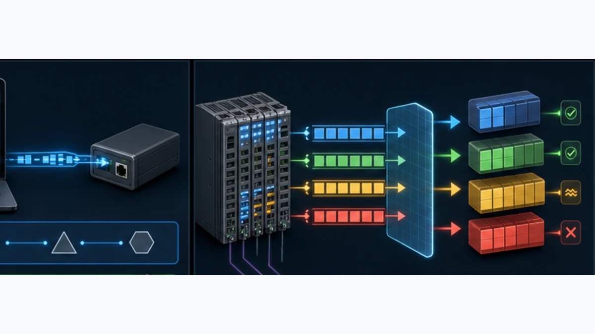
| Physical design field | Record | Failure prevented or exposed |
|---|---|---|
| MainDevice port | target label, logical adapter, physical port and MAC/PCI reference | wrong NIC or cable is activated |
| topology | ordered device list and every branch/port relationship | moved terminal or unexpected junction changes the logical chain |
| segment cable | category/product, length, connector and environmental rating | intermittent CRC/link errors and overlength assumptions |
| E-bus demand | each terminal current plus coupler/feed margin and derating | terminal row becomes unstable under load |
| field/load power | voltage, current, protection, groups and safe isolation | communication is healthy while an actuator supply is absent |
| identity policy | Vendor ID, product code, revision/serial check rules | look-alike replacement changes the process map |
| failure response | affected SyncUnit, stale-value rule, output fallback and machine action | downstream faults propagate without a defined response |
Freeze TwinCAT, ESI, topology and Startup configuration
Archive the complete engineering compatibility set
An EtherCAT SubDevice Information file, or ESI, is XML that describes product identity, process data, mailbox capabilities and synchronization options. Beckhoff documents the TwinCAT 3 default ESI location as C:\TwinCAT\3.1\Config\Io\EtherCAT. A TwinCAT installation contains the Beckhoff ESI set current when that build was produced; third-party and newer device descriptions require controlled installation from the manufacturer. TwinCAT reads changed descriptions when a new System Manager window opens.
Do not replace ESI files casually on a shared engineering machine. Archive the approved source, version/checksum and project. Compare newly available descriptions and release notes. A device EEPROM can expose identity and configuration information, but that does not eliminate the need for the correct engineering description and an approved offline configuration.
| Controlled artifact | Why it changes behavior | Release evidence |
|---|---|---|
| TwinCAT XAE/XAR | determines configurator, runtime and library behavior | exact build/packages and target image |
| I/O project | owns adapter, topology, identity checks, PDOs, Startup and task binding | source revision plus activated configuration backup |
| ESI files | define device variants, PDO options, mailbox and synchronization data | manufacturer source, filename, date/version and checksum |
| device firmware/revision | can alter supported mappings, diagnostics and replacement compatibility | online identity and approved revision policy |
| PLC mapping | connects process-image symbols to application variables | mapping export/diff and typed interface version |
| Startup list/CoE baseline | reapplies parameters during EtherCAT startup | reviewed index/subindex, value, state and device scope |
| timing design | owns task period, phase, watchdog and DC mode/reference | measured baseline and acceptance limits |
Treat online CoE edits as changes, not experiments that disappear
CoE mailbox access can read or write a device object dictionary when supported. Some online changes take effect immediately and may be retained non-volatilely by a device. If an approved setting must survive replacement and restart, place the exact documented operation in the TwinCAT Startup list or another controlled vendor workflow. If it is only a temporary diagnostic change, record and restore the baseline.
Never browse a CoE list and write plausible values by index on a live machine. Index/subindex meaning, data type, valid range, required state and persistence are device-specific. Preserve the first error and the original value. A successful ADS/CoE transaction proves the service completed; it does not prove the resulting machine behavior is acceptable.
Discover EtherCAT devices and compare before accepting
Scan only in a controlled Config Mode state
Beckhoff's TwinCAT workflow scans I/O while the target is connected and TwinCAT is in Config Mode. It can find the EtherCAT interface, couplers and attached terminals, then offer a FreeRun view. On an existing machine, save the known-good project first and place outputs/energy in the approved safe state. Never make “scan, accept all, activate” the maintenance procedure.
Compare the discovered list with the released bill of materials, electrical drawings, offline tree and cabinet labels. Identity, order, branch port and revision policy all matter. A missing terminal can shift downstream position-based assumptions. A physically similar terminal can expose a different PDO. A discovered device that TwinCAT labels unknown may indicate a missing/old ESI, unexpected identity, damaged EEPROM or a product outside the approved set; identify it before creating a generic placeholder.
Use a structured diff gate
| Diff result | Meaning | Required action |
|---|---|---|
| exact match | found order and identities meet released policy | proceed to mapping and offline/online compare |
| revision differs but policy allows it | replacement may be compatible within configured check rules | verify manufacturer compatibility, PDOs and functional acceptance |
| product code differs | not the configured SubDevice | stop; install approved hardware or engineer a controlled change |
| terminal order differs | topology/process image may differ | restore physical order or review the entire mapping and drawings |
| unknown device | ESI/identity cannot be resolved confidently | obtain exact manufacturer ESI and inspect device identity/EEPROM |
| unexpected branch or missing link | physical topology differs or path is interrupted | inspect ports, cable, power and junction order before activation |
| extra device | unreviewed hardware exists in the discovered chain | identify ownership and include it only through change control |
Scanning helps build a new bench project, but an offline configuration is often safer for repeat machines because it makes the intended identity explicit before hardware is present. Whichever route is used, the released project—not the latest opportunistic scan—owns the production topology.
Live mini-lab
Try it: press START, then STOP
A stop-dominant seal-in rung: START latches the motor output through its own contact, and STOP breaks the circuit.
Watch the output lamp: it stays on after START until you press STOP.
Free to start · runs in your browserOpens plcsimulationsoftware.com — same team
Configure PDOs, Startup data and device identity
Select the exact PDO variant before linking variables
The TwinCAT Process Data tab presents Sync Managers, PDO assignment and PDO content described by the device. For mailbox-capable devices, Beckhoff documents SM0/SM1 for mailbox traffic and commonly SM2 for output process data and SM3 for input process data. Some PDOs are fixed or mandatory; some devices provide predefined compatible PDO sets; some permit configurable content. Follow the exact device manual.
A changed PDO assignment is not merely a PLC-symbol edit. Beckhoff notes that the SubDevice must pass the PreOp-to-SafeOp transition and the configuration must be re-enabled for a new assignment. Changing the process image generally requires configuration activation. Plan the stop, backup and output state accordingly.
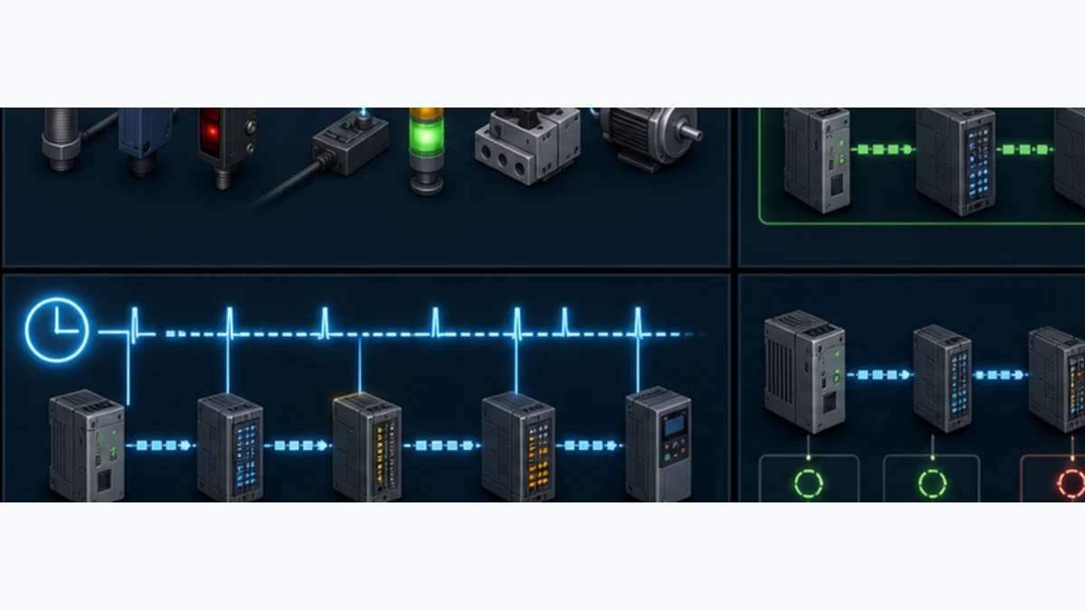
| Contract field | Example form | Acceptance proof |
|---|---|---|
| physical source | coupler/terminal/channel and connector | cabinet stimulus reaches the intended channel |
| EtherCAT direction | SubDevice TxPDO to PLC input or RxPDO from PLC output | direction is named from the device viewpoint and verified in I/O tree |
| PDO identity | object/index and selected predefined assignment | offline selection matches online device support |
| process layout | byte.bit offset, width and TwinCAT I/O symbol | asymmetric patterns prove no shifted or swapped fields |
| PLC type | BOOL, signed/unsigned integer, structure or approved application type |
type width/sign and alignment are reviewed |
| engineering conversion | raw range, scale, offset, unit and limits | low/mid/high and negative cases match a reference |
| status/quality | device status word, WcState, age and application validity |
bad communication or channel state invalidates use |
| fallback | hold, substitute, stop, alarm or inhibit per risk design | cable/device loss produces the witnessed response |
Keep identity checks strict enough for the process risk
TwinCAT can check Vendor ID and product code and can apply revision rules during startup. Choose the policy deliberately. Allowing a compatible higher revision may simplify service; it still requires vendor evidence and representative validation. Enforcing an exact revision reduces variation but can block a legitimate spare. Serial-number or explicit identification features can distinguish identical products when position alone is insufficient.
The device tree and Startup list should tell a future engineer what must be present and why. Use descriptive names tied to drawings and functional locations. Avoid hiding the only identity record inside an HMI label or unversioned spreadsheet.
Link EtherCAT process data to typed PLC interfaces
Map through a dedicated hardware boundary
Declare PLC I/O variables with appropriate input/output allocation, link them to the intended TwinCAT I/O symbols and expose a separate normalized application interface. Directly scattering hardware-linked variables through machine logic makes revision, fallback and simulation difficult. A dedicated function block or structure can preserve raw value, status, freshness, engineering value and command ownership.
Manual links, generated mappings and TcLinkTo attributes can all be valid when governed consistently. Attribute paths depend on I/O tree names and hierarchy, so a renamed device can break an assumed path. Review the mapping view/diff after topology or PLC-structure changes. An unlinked variable, a linked symbol with the wrong width or a retained application value can look plausible online.
Prove value and validity separately
For each input, capture raw bytes/bits at the I/O symbol, linked PLC variable and normalized application tag. Test asymmetric values such as 1, 2, 4, 127, 128, negative values and non-round engineering points as applicable. This exposes bit shifts, sign and byte-order mistakes better than testing zero and full scale.
For each output, keep the machine inhibited, command one bounded pattern, confirm the raw output PDO and measure the field response with the approved method. Then remove communication and confirm the designed watchdog/fallback. The output test must not rely on the same PLC value that generated the command as its only feedback.
| PLC interface member | Purpose | Rule |
|---|---|---|
Raw |
exact process-image value | preserve for commissioning and fault evidence |
CommValid |
bus/PDO communication acceptance | false when relevant frame/device WC or state is invalid |
ChannelValid |
device/channel diagnostic acceptance | independent from EtherCAT link health |
Fresh or age |
application update expectation | reject stale retained values after a timeout justified by timing design |
Value |
typed/scaled engineering value | update or accept only under explicit validity policy |
Command |
bounded requested output | owned by one state/authority path |
Feedback |
independent process or device response | never infer solely from echoed command data |
FaultFirst |
first failed layer and timestamp | retain until acknowledged under the alarm philosophy |
Set the EtherCAT sync task and Distributed Clocks deliberately
Bind cyclic I/O to the intended real-time task
TwinCAT cyclic tasks drive fieldbuses and process-image copies. Choose the EtherCAT Sync Task and cycle from the real application requirements, target capacity, device limits and motion architecture. Faster is not automatically better. A bus cycle below a terminal's supported conversion or minimum cycle can create errors without improving the physical measurement. Multiple tasks and phases can make controller-to-field latency differ from the nominal bus period.
Measure target task execution, jitter/overrun indicators, EtherCAT frame timing and consumer update under representative PLC, motion, HMI, logging and acyclic load. Define acceptance percentiles or worst-case limits appropriate to the machine. Do not publish one “Beckhoff EtherCAT cycle time” as though every controller and terminal supports it.
Enable Distributed Clocks only for devices and functions that need it
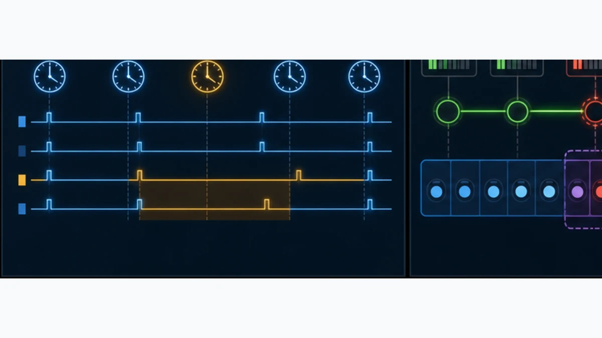
EtherCAT Distributed Clocks aligns supported SubDevice clocks to a reference. TwinCAT commonly selects the first suitable DC device as the reference, though the exact configuration can be controlled. Supported modes can include FreeRun, synchronization to a Sync Manager event, and DC synchronization using SYNC events. The available modes and minimum cycles come from each device/ESI/manual.
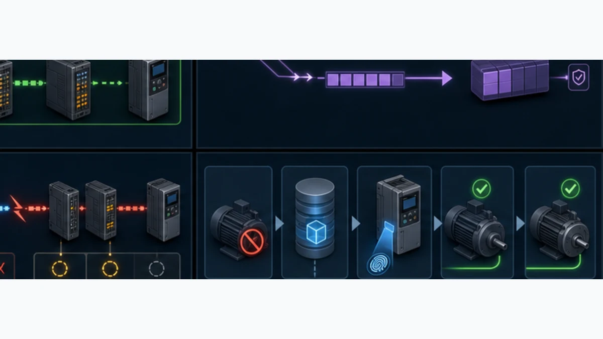
| Mode or timing choice | Appropriate question | Required evidence |
|---|---|---|
| FreeRun | may the device run on its own local cycle? | device supports it and observed value/timing meets the process need |
| SM-synchronous | should device processing follow passing process-data events? | supported mode, correct PDO/SM and stable operation under load |
| DC synchronous | must multiple device events align to a shared clock? | DC support, reference selection, cycle/shift, sync status and measured phase |
| input-based DC | should sampling align to the input timing model documented by the device? | exact product procedure and timestamp/latency acceptance |
| faster task | does shorter controller period improve the required response? | CPU headroom and end-to-end measurement, not nominal period alone |
| different SyncUnits | is fault containment worth additional datagram overhead? | documented fault model, measured load and WC behavior |
DC is not a checkbox that guarantees motion quality. Servo profile, drive task, NC/motion configuration, reference clock, cabling, CPU isolation and machine mechanics also govern the result. If a DC device cannot reach or retain OP, inspect its supported mode, cycle, shift/reference and task start before replacing hardware.
Commission the complete Beckhoff EtherCAT chain
Move from identity to output in a fixed order
Commission under the site's electrical, mechanical and functional-safety procedures. Back up the running project and device parameters before activation. Separate control power from hazardous actuator energy where the design permits. Have a tested rollback route and local access to the target.
- Record target, TwinCAT build/packages, adapter, ESI set, I/O project, PLC revision and all device identities.
- Verify drawings, cable path, coupler/terminal order, power groups, E-bus total and field/load supplies with energy controlled.
- Compare the offline tree with a controlled scan or online identity; resolve every difference before accepting it.
- Review PDO assignments, Startup list, identity checks, SyncUnits, sync task and DC modes.
- Compile the complete TwinCAT solution and review mapping/configuration changes, warnings and target compatibility.
- Activate in the approved safe state; keep PLC commands and physical energy inhibited.
- Prove target RUN/Config state, MainDevice OP, configured device count, each required SubDevice state,
DevStateand frame WC health. - Stimulate every input and prove raw, linked, scaled, status, freshness and application behavior.
- Exercise bounded outputs one at a time, measure field response and prove watchdog/fallback before enabling machine sequences.
- Run CoE/Startup, event, cable-loss, power-loss, wrong-device and replacement tests that the design requires.
- Measure task/DC/cyclic behavior under representative maximum load and retain the baseline.
- Re-enable energy through the validated safety procedure and perform the machine functional acceptance.
| Acceptance case | Stimulus | Evidence to retain | Reject if |
|---|---|---|---|
| cold start | power-cycle through approved sequence | device order/identity, state transition and Startup results | manual online edits are required to reach normal operation |
| input mapping | apply multiple known field values | raw I/O, PLC type/scale, status and reference measurement | only a convenient zero/full-scale point was tested |
| output mapping | command bounded patterns with energy controlled | PDO, terminal LED/state, independent field measurement and fallback | output energizes unexpectedly or echo is the only proof |
| cable interruption | open a selected link safely | first timestamp, topology, WC/state, CRC/link data and application response | retained input remains valid or machine response is undefined |
| wrong device | install/introduce a controlled identity mismatch | startup check and rejection/diagnostic | look-alike device is silently accepted with different map |
| replacement | fit approved spare with known baseline | identity, Startup parameters, map, diagnostics and functional test | OP alone is counted as acceptance |
| representative load | run PLC/motion/HMI/logging and necessary acyclic services | task, frame, DC and consumer timing distributions | average passes while overruns/tails violate the process requirement |
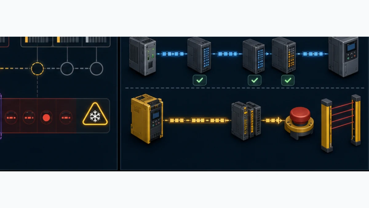
Diagnose Beckhoff EtherCAT faults from state to physical port
Start with the minimum cyclic health contract
Beckhoff's EtherCAT System documentation recommends monitoring at least the MainDevice DevState and each cyclic frame's Working Counter state such as Frm0WcState; healthy target values are zero. It also exposes per-SubDevice state and optional WcState. For the documented WcState, 0 means valid real-time communication in the last cycle and 1 means invalid. When invalid, related input data can remain at the last valid value. Therefore, a stable-looking value must be rejected or marked stale when its communication validity is bad.
A Working Counter mismatch means the expected datagram memory interactions did not all occur. It is a powerful symptom, but one command may include several devices in the same SyncUnit. It does not uniquely identify which terminal failed. Use state, actual topology, link/lost-frame information, port CRC counters, power and identity to localize the first failed boundary.
Read the state transition that failed
EtherCAT states narrow the configuration layer:
- INIT has no process-data or mailbox operation; establish interface/device presence and initialization.
- PREOP allows mailbox communication but not cyclic process data; failures progressing onward often involve identity, Startup/CoE, PDO or basic configuration.
- SAFEOP provides inputs/process-data operation while outputs remain in a safe behavior by default; inability to reach OP can involve valid output data, watchdog, sync/DC or device-specific conditions.
- OP permits normal process and mailbox communication, but still requires WC, channel status and application validity.
- BOOT is a firmware-service state, not a normal operating target.
Do not repeatedly clear an EtherCAT error before recording its AL status, current/requested state, timestamp and surrounding events. The failed transition contains more information than the later generic “not OP” symptom.
Use topology and CRC counters to find the physical boundary
TwinCAT's online topology view compares configured and actual nodes and displays port CRC error counters. Beckhoff identifies damaged frames, cable faults, contact problems and loose connectors as possible CRC causes. Record counters, clear them once under a controlled test, then observe which port increments with a repeatable stimulus such as cable motion or machine cycle. Do not replace the terminal solely because its port shows a count; the damaged frame or link can involve the cable and adjacent connection.
| Symptom | First discriminating evidence | Likely layer | Next controlled action |
|---|---|---|---|
| no EtherCAT device/adapter available | target identity and Compatible Devices/Adapter selection | target, driver or NIC support | compare exact port/driver with target documentation; do not activate another NIC blindly |
| scan finds no boxes | adapter link, target Config Mode, first coupler power and cable | physical/adapter boundary | verify selected physical port, coupler supply and first segment |
| unknown or wrong device | online Vendor ID/product/revision versus ESI/project | identity/description | install exact approved ESI or correct hardware; retain original project |
| stuck PREOP | AL status, Startup entry and mailbox response | identity, CoE or initialization | preserve error; compare ESI, revision and each startup write/state |
| stuck SAFEOP | PDO sizes/assignment, valid outputs, watchdog and DC sync | process configuration/timing | restore approved PDO set; verify task and device sync requirements |
MainDevice DevState nonzero |
exact bit/state plus device count and topology | aggregate network state | identify first non-OP/missing/link device before resetting |
| frame WC state nonzero | affected frame/SyncUnit and per-device state/WC | cyclic processing | narrow to participating devices, topology, power and identity |
WcState = 1 with plausible input |
input age/raw capture and affected SyncUnit | invalid/stale cyclic data | invalidate application value; locate state/topology/physical fault |
| CRC counter grows | exact port, time and physical stimulus | cable/connector/EMC/link | inspect both ends, cable route and connector; substitute known-good segment |
| devices OP but value wrong | selected PDO, link, raw bits, type, sign/scale and channel status | mapping/application | apply asymmetric known values and trace field-to-application |
| intermittent DC Sync lost | task overruns, reference, cycle/shift and device DC status | synchronization/load | restore approved timing and measure under representative load |
| outputs fail while bus healthy | load supply, terminal/channel diagnostics and command/fallback | field power/channel/application | prove supply and raw output separately from feedback |
Monitor EtherCAT health in the TwinCAT PLC
Link fast cyclic diagnostics and request detailed state asynchronously
Make the minimum real-time validity fields part of the PLC hardware interface: relevant MainDevice DevState, frame FrmXWcState, required per-device WcState, device/channel status and application age. Evaluate them in the task that consumes the data or transfer them with an explicit freshness contract. Log the first transition and enough context to diagnose it; do not flood the alarm system every scan.
The Tc2_EtherCAT library provides asynchronous ADS-based function blocks such as FB_EcGetMasterState, FB_EcGetSlaveState and functions for broader device diagnostics. Their request model uses an execute edge, bBusy, completion/error and nErrId. Do not retrigger every cycle or overwrite the first error. The AMS Net ID and fixed SubDevice address must come from the released configuration, not a copied sample.
CoE reads/writes such as FB_EcCoeSdoReadEx and FB_EcCoeSdoWriteEx are service operations. Serialize and rate-limit them as documented. Use cyclic PDO data for routine real-time values. A maintenance HMI that launches arbitrary SDO writes can change device behavior and must be replaced by bounded, authorized operations.
| Runtime diagnostic | Cadence | What it proves | What it does not prove |
|---|---|---|---|
DevState |
cyclic | aggregate MainDevice/device/link state is at expected zero | correct value scaling or field power |
FrmXWcState |
cyclic | expected commands in that frame had valid WC | unique failing device when a SyncUnit spans several devices |
device WcState |
cyclic where exposed | device's cyclic data exchange was valid last cycle | channel measurement is physically valid |
| device/channel status | cyclic/event | product reports a channel/device condition | EtherCAT link is necessarily the cause |
FB_EcGetMasterState |
event/diagnostic request | detailed MainDevice EtherCAT state via ADS | deterministic per-scan health by itself |
FB_EcGetSlaveState |
event/diagnostic request | selected SubDevice EtherCAT/link state | why a mapping or field signal is wrong without more evidence |
| CRC/topology snapshot | event/maintenance | spatial physical evidence over a time window | automatic proof that one named component must be replaced |
| application age/validity | cyclic | consumer accepts a fresh, good value under its contract | protocol conformance or functional safety |
Preserve first fault, consequence faults and recovery separately
When one coupler loses power, downstream states, frame WC and many application alarms may change in the same cycle. Latch the first observed layer with monotonic time, state, WC, topology/device position and target/task context. Keep consequence alarms for operator awareness but do not let them replace the first-out record.
Recovery should be an explicit state. Communication returning to OP is necessary, not sufficient. Require stable WC/state for a justified interval, valid channel data, application reinitialization and any process-specific acknowledgement before resuming commands. Safety restart rules remain independent.
Govern replacement, security and functional safety
Make terminal replacement reproducible
An approved spare needs more than a matching terminal family name. Verify product code, revision policy, terminal position, ESI, selected PDOs and device parameters. If settings were changed online but never entered in the Startup list or controlled backup, the replacement can communicate with defaults and behave differently. After replacement, rerun identity, raw mapping, diagnostics, fallback and the necessary functional calibration or actuator test.
For repeat machines, store a recovery pack containing the TwinCAT solution, source revision, XAE/XAR/package list, target image information, ESI files, mapping export, Startup/CoE baseline, device firmware, licenses, safety project references, drawings and witnessed acceptance results. Test restoring it on representative spare hardware before an outage.
Treat activation and parameter access as privileged OT changes
TwinCAT configuration activation, PLC download, adapter changes and CoE writes can change field behavior. Apply named user roles, least privilege, controlled engineering routes, backups, signed/protected project features where appropriate and current Beckhoff security guidance/advisories. Restrict operating-system access to authorized users. Segment the engineering and upstream networks; do not expose ADS or engineering services merely to simplify remote service.
Cybersecurity does not come from EtherCAT's deterministic cycle. The MainDevice runtime, engineering workstation, routes, packages, remote access and archives are part of the attack/change surface. Record who activated which project and when.
Ordinary EtherCAT status is not a safety function
Standard EtherCAT PDOs, WcState, terminal diagnostics and PLC fallback are ordinary control evidence. Safety over EtherCAT, or FSoE, is a separate safety protocol with safety containers, certified compatible components and a validated safety application/lifecycle. A standard terminal mapped into a safety-capable Beckhoff controller does not become safety-rated.
Keep emergency stop, guard, safe motion and similar credited functions under the machine risk assessment and approved safety architecture. Test ordinary communication loss and the safety response separately. Never use a browser simulator, PLC status bit or unvalidated timeout as the only risk-reduction measure.
Frequently asked questions
How do I configure EtherCAT on a Beckhoff PLC in TwinCAT 3?
Select the exact TwinCAT runtime target and supported EtherCAT interface, create the EtherCAT I/O device, add or safely scan the SubDevice chain in Config Mode, compare it with the released topology, install the exact ESI files, select PDOs and Startup parameters, link typed PLC variables, assign the sync task/DC modes, then activate and commission under controlled energy. Prove identity, state, WC, raw data, validity, outputs and recovery.
Is the Beckhoff EK1100 an EtherCAT master?
No. The EK1100 is an EtherCAT SubDevice bus coupler that connects 100BASE-TX EtherCAT to a Beckhoff E-bus terminal row. The TwinCAT target and its configured EtherCAT device perform the MainDevice role. Verify the exact EK1100 variant's power, temperature, interface and terminal limits.
How do I scan EtherCAT devices in TwinCAT 3?
Connect to the correct target, place TwinCAT in Config Mode, right-click the I/O Devices node and use Scan, then scan the selected EtherCAT interface for boxes. On an existing machine, first save the known-good project and establish a safe output state. Compare every discovered identity, order and branch with the released configuration before accepting or activating it.
Where do ESI files go in TwinCAT 3?
Beckhoff documents C:\TwinCAT\3.1\Config\Io\EtherCAT as the default TwinCAT 3 EtherCAT ESI directory. Obtain files from the device manufacturer, archive their version/checksum, close and reopen the relevant engineering/System Manager window after controlled installation, and verify that the exact product/revision and PDO options appear.
How do I map EtherCAT PDOs to TwinCAT PLC variables?
Choose the approved input/output PDO assignment on the device's Process Data tab, activate/re-enable the configuration through the required state transition, declare correctly typed PLC I/O variables and link each I/O symbol to the dedicated hardware interface. Prove direction, bit/byte offset, width, sign, scaling, status and stale-data handling with asymmetric field tests.
What do DevState, Frm0WcState and WcState mean in TwinCAT?
DevState summarizes MainDevice/device/link status; Beckhoff's normal target is zero. FrmXWcState identifies invalid Working Counter results for commands in a cyclic frame; its healthy target is zero. Per-device WcState is 0 for valid cyclic communication in the last cycle and 1 for invalid. A bad WC can leave old input values visible, so the application must evaluate it.
Why is a Beckhoff EtherCAT terminal stuck in PREOP or SAFEOP?
PREOP failures commonly point toward identity, ESI, mailbox/Startup or initialization evidence. SAFEOP failures more often involve PDO assignment/size, valid output data, watchdog or synchronization/DC settings. Preserve the exact AL status and failed transition, compare it with the product manual, and correct that boundary before clearing the error or replacing hardware.
How do I locate an intermittent EtherCAT cable fault in TwinCAT?
Capture the first state/WC event, open online topology and record port CRC/link counters and timestamps. Clear counters once under a controlled test, reproduce the condition and see which boundary increments. Inspect both connector ends, cable route, motion, shielding/grounding and nearby power events. Substitute a known-good segment before blaming a terminal solely because its port displays the counter.
When should I enable Distributed Clocks in TwinCAT?
Use DC when the exact devices and machine function require synchronized sampling, outputs, timestamps or motion. Select only modes supported by the ESI/device manual, verify the reference clock, cycle/shift and task binding, then measure synchronization and end-to-end behavior under load. Leave devices FreeRun or SM-synchronous when that is the documented and sufficient design.
Is ordinary Beckhoff EtherCAT data functionally safe?
No. Ordinary EtherCAT PDOs, states and diagnostics are not by themselves a credited safety channel. Functional-safety communication uses Safety over EtherCAT/FSoE with certified components, a safety application and a validated lifecycle. Keep standard control diagnostics outside the credited PL/SIL function unless the exact approved safety design states otherwise.
Practical next step
Export the current TwinCAT project and photograph the target, EtherCAT port, coupler and terminal labels. Create one table with target/port → configured device → physical order → ESI/revision → PDO → PLC variable → validity → field test. Resolve the first blank or mismatch before scanning or activating anything. Then test one input, one output and one controlled cable loss from field signal to application response.
Sources, review scope and limitations
This guide was reviewed on August 30, 2026. TwinCAT packages, target operating systems, device revisions and product support change. Beckhoff documentation often retains master/slave wording in UI/API names; this page uses ETG MainDevice/SubDevice terminology while preserving exact function-block names. Only the current product manual, approved project, risk assessment and witnessed tests authorize an installation.
- Beckhoff, TwinCAT 3 I/O device selection and supported-target filtering.
- Beckhoff, TwinCAT EtherCAT Adapter tab and compatible-device workflow.
- Beckhoff, TwinCAT 3 Basics manual, including real-time Ethernet adapter installation.
- Beckhoff, EtherCAT System Manual Version 6.0.0.
- Beckhoff, TwinCAT 3 EtherCAT Process Data tab, Sync Managers and PDO assignment.
- Beckhoff, ESI device-description installation and TwinCAT 3 directory.
- Beckhoff, EtherCAT default settings, DevState, Working Counter, SyncUnits and runtime diagnostics.
- Beckhoff, TwinCAT EtherCAT Online tab and per-port CRC counters.
- Beckhoff, TwinCAT EtherCAT Topology dialog.
- Beckhoff, EtherCAT State Machine behavior for INIT, PREOP, SAFEOP, OP and BOOT.
- Beckhoff, EtherCAT synchronization modes and Distributed Clocks.
- Beckhoff, EK1100 coupler function and E-bus supply boundary.
- Beckhoff, EtherCAT wire-bound cabling and segment/E-bus notes.
- Beckhoff,
FB_EcGetMasterStatein the Tc2_EtherCAT library. - Beckhoff,
FB_EcGetSlaveStatein the Tc2_EtherCAT library. - Beckhoff, CoE access with
FB_EcCoeSdoReadExandFB_EcCoeSdoWriteEx. - Beckhoff, TwinCAT 3 security management and user access rights.
- EtherCAT Technology Group, EtherCAT Compendium: MainDevice, SubDevice, state, DC, error handling and user aspects.
- EtherCAT Technology Group, EtherCAT Implementation Guide and ESI definition.
- EtherCAT Technology Group, Safety over EtherCAT and the black-channel safety boundary.
Now run it · free to start
Follow plant data from sensor to SCADA
Fieldbus versus Ethernet, Modbus, EtherNet/IP, PROFINET, OPC UA and MQTT, then SCADA layers and alarms, taught on simulated equipment. Free to start.
Ownership disclosure: PLC Programming IO and PLC Simulation Software are operated by the same publisher.
PLC Programming IO Editorial Team
Industrial automation education, references, and software testing
The PLC Programming IO Editorial Team publishes sourced industrial-automation education and documents how material is reviewed, tested, and corrected. A team byline means the publisher is responsible for the page; it does not represent a fictional person or imply an engineering licence.
Coverage:
- • PLC programming concepts and examples
- • Vendor software tutorials and comparisons
- • SCADA, HMI, protocols, and instrumentation
- • Training, careers, and reference material
Review standard:
- • Prefer primary and official sources
- • Record software versions when material
- • Separate tested facts from estimates
- • Publish material corrections
Important scope note
This site provides education, not project-specific engineering approval. Safety, code, and compliance decisions require a qualified person with access to the actual machine and jurisdiction.