OpenPLC EtherCAT: Runtime v4 Setup, PDO Mapping and Diagnostics
Configure the OpenPLC Runtime v4 EtherCAT plugin, dedicate the correct NIC, import ESI files, map PDO channels to IEC variables and diagnose state or working-counter faults.
Review status: Editorially reviewed against OpenPLC Runtime v4.1.10 source/release evidence, current Autonomy Logic EtherCAT editor documentation and EtherCAT Technology Group references; exact host, NIC, OS, runtime build, plugin, ESI, device firmware, PDOs, timing, electrical installation and safe process behavior require project-specific verification
Direct answer: OpenPLC EtherCAT support is versioned and plugin based
OpenPLC Runtime v4 supports an EtherCAT MainDevice through a native EtherCAT plugin. The current runtime repository builds native plugins, its default plugin configuration includes libethercat_plugin.so, and the current editor documentation provides EtherCAT bus scanning, ESI repository, channel mapping, timing and diagnostics workflows. The plugin entry is disabled by default in plugins_default.conf, so the existence of OpenPLC v4 does not prove that EtherCAT is enabled, built or connected on a particular host.
Use a current Runtime v4 release and a supported OpenPLC Editor/Autonomy Edge workflow. As reviewed on August 30, 2026, the latest published runtime release is v4.1.10, released August 11, 2026. The old OpenPLC v3 repository is archived, read-only and marked end of life. It contained an earlier EtherCAT build path, but it should not be presented as the current default for a new project.
The minimum defensible path is: identify the exact v4 runtime build; prove that its native EtherCAT plugin and required packet-access dependency load; reserve a dedicated compatible Ethernet interface; connect a line of powered EtherCAT SubDevices; import the manufacturer ESI XML for every exact product/revision; scan or construct the bus; map ESI-derived TxPDO and RxPDO channels to IEC located variables; select a realistic cycle and watchdog; then prove INIT, PREOP, SAFEOP and OP transitions, expected working counter, data direction, scaling, fault response and deliberate recovery.
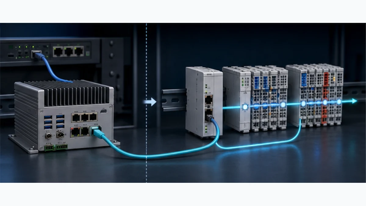
This page owns the OpenPLC-specific v4 implementation and troubleshooting task. Use the EtherCAT PLC guide for protocol-wide frame processing, topology, ESI, Distributed Clocks, PDO/mailbox and state-machine fundamentals. Use the OpenPLC hub for the wider editor, runtime, hardware and tutorial surface. Those broader owners should link here for the exact integration rather than repeating a second setup procedure.
Establish the OpenPLC generation and support boundary
Runtime v4 is not the archived v3 EtherCAT path
Search results and old forum posts often point to ./install.sh linux ethercat in OpenPLC v3 or to a community ethercat_src repository. The archived v3 README still documents that capability, which makes the advice look current. However, the repository was archived on April 4, 2026 and its README says the project reached end of life and was replaced by Runtime v4.
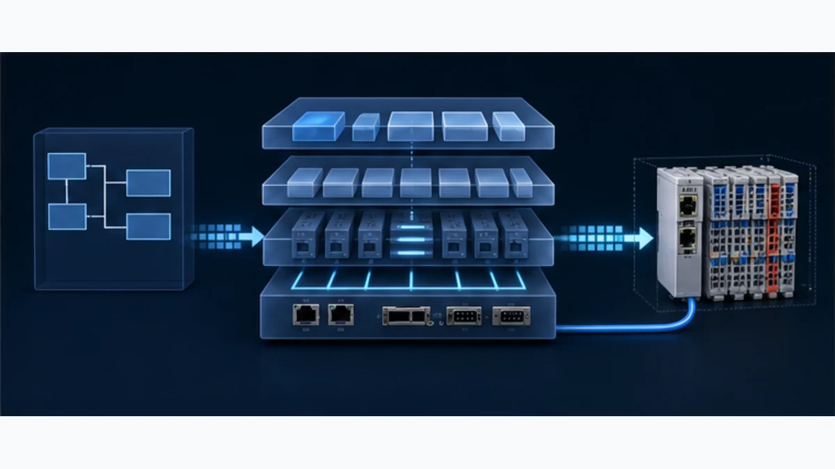
Runtime v4 has a different architecture: a headless runtime core, an editor/runtime API and a plugin system with native C/C++ shared libraries. Its installer scans native plugin directories, initializes required submodules and builds native plugins. Its default plugin list names an EtherCAT native plugin and a JSON configuration path. Treat v3 and v4 as separate products with separate installation, project, configuration and diagnostic instructions.
| Evidence found | What it proves | What it does not prove |
|---|---|---|
| Runtime v4 latest release is v4.1.10 | a dated current release exists | the installed host is on that release or supports the selected NIC/device |
plugins_default.conf lists libethercat_plugin.so |
the current project includes an EtherCAT native-plugin route | the plugin is enabled; the default row shows it disabled |
| Runtime installer builds native plugins and mentions SOEM/EtherCAT requirements | source installation includes the build workflow and dependencies | every packaged image or custom fork contains a working binary |
| current editor docs expose EtherCAT bus, ESI, mapping and diagnostics views | a supported engineering workflow exists for Runtime v4 | every editor build/account/target exposes the same capability |
| v3 README contains an EtherCAT install option | the old generation had a documented experimental/integrated route | v3 is maintained or preferred for a new installation |
“OpenPLC supports EtherCAT” is a five-part claim
A project can claim support only after all five rows are true: the editor can represent the bus, the runtime has the plugin, the operating system permits raw Ethernet access, the NIC/driver can cycle the actual network, and the SubDevice configuration matches. Missing any row produces a partial installation, not a working controller.
| Boundary | Required proof | Frequent mistaken shortcut |
|---|---|---|
| editor capability | EtherCAT bus editor is available for the connected v4 target | seeing an EtherCAT option in a menu means the target supports it |
| runtime capability | exact runtime version reports the EtherCAT discovery/cyclic service and loads the plugin | installing the editor also installs/configures the fieldbus runtime |
| host capability | required permissions, packet driver, real-time resources and dedicated NIC are available | any USB Ethernet adapter or container bridge is deterministic |
| device description | current manufacturer ESI matches vendor ID, product code and revision | a similarly named XML file is close enough |
| application contract | PDO direction, IEC addresses, types, scale, quality and safe response pass | an OP state makes every mapped value correct and safe |
Choose the host, operating system and network interface
Use one dedicated EtherCAT NIC
Current Autonomy documentation tells vPLC users to mark the EtherCAT NIC as a Dedicated Interface and states that the runtime requires exclusive raw-Ethernet access. The bus editor also warns against sharing that interface with management traffic because intermittent working-counter problems can result. Keep runtime/editor management, Internet access and ordinary plant Ethernet on another interface.
An EtherCAT segment starts from the selected MainDevice NIC and enters the IN port of the first SubDevice. Standard switched Ethernet infrastructure does not belong between the MainDevice and first SubDevice unless an exact EtherCAT product architecture explicitly provides the required function. Follow the SubDevice line/branch/junction topology supported by the products. A conventional managed switch is not an EtherCAT junction.
| Host option | Plausible use | Required validation | Hold condition |
|---|---|---|---|
| native industrial Linux PC | engineering bench or controlled machine runtime | v4 build/plugin, compatible NIC/driver, dedicated interface, scheduler/IRQ behavior and measured jitter | shared office NIC, unsupported kernel/driver or uncontrolled host workload |
| Autonomy Edge vPLC | managed runtime and current documented bus/editor workflow | runtime v4 capability, NIC marked Dedicated Interface and assigned to the vPLC | discovery banner says service unavailable or NIC was not dedicated |
| Windows runtime | supported current release where the packet driver/plugin workflow is present | exact v4 package, Npcap requirement, plugin load and representative cyclic test | copying Linux .so instructions or assuming a desktop adapter is real-time capable |
| Docker/container | reproducible software test with explicitly passed raw interface/capabilities | host networking/interface ownership, permissions, image version and real hardware proof | ordinary Docker bridge/port mapping is treated as the EtherCAT wire |
| Raspberry Pi or small SBC | education or bounded experiment after exact platform proof | architecture build, NIC/driver, electrical interface, CPU isolation and load/jitter results | “OpenPLC runs on Pi” is used as proof of EtherCAT production suitability |
The v4 installer requests privileges for real-time scheduling and builds native plugins. Those privileges increase the security and availability consequences of the host. Do not use --privileged as a blanket fix copied from a forum. Grant the smallest documented capabilities, isolate the fieldbus interface, restrict runtime management access, retain signed/current packages and validate the exact deployment model.
Freeze a host evidence sheet
Record OS distribution and kernel, runtime/editor versions, installation source and checksum, plugin binary and configuration, NIC vendor/device/driver/firmware, PCI or USB path, interface name/MAC, CPU affinity, scheduler policy, interrupt placement, cycle time, worst observed jitter and device count. Interface names can change after hardware replacement; the project needs a stable identification/recovery method rather than a remembered eth0 string.
| Host evidence | Example record | Acceptance question |
|---|---|---|
| release | OpenPLC Runtime v4.1.10, package/source checksum | is this the tested build, not merely “v4”? |
| plugin | exact library path, load status and config checksum | did the runtime load the intended EtherCAT plugin? |
| packet access | Linux raw interface or current Windows/Npcap path | can discovery and cyclic frames use the fieldbus NIC exclusively? |
| NIC | PCI ID, driver, firmware, interface/MAC | will replacement or reboot select the correct port? |
| timing | configured bus cycle, task interval, measured max/percentiles | does the host meet the application age/jitter requirement under load? |
| security | management NIC, firewall, credentials, update and log access | can the fieldbus stay isolated while the runtime remains maintainable? |
Install and prove the v4 EtherCAT plugin
Start from the current release, not a copied branch command
For source installation, follow the current OpenPLC Runtime README and installer for the selected release. The repository documents CMake 3.28+ and notes that native plugins such as EtherCAT are built during setup. The installer initializes git submodules needed by plugins that vendor libraries such as SOEM, builds shared libraries and copies them to the central plugin output directory.
For a packaged installer or container, do not assume its contents from the source tree. Confirm the release’s platform assets, current documentation and runtime logs. The current default plugin file gives the conceptual row:
ethercat,./build/plugins/libethercat_plugin.so,0,1,./core/src/drivers/plugins/native/ethercat/ethercat_config.json,
The fields are name, native library path, enabled flag, native-plugin type and configuration path. The 0 in the default enabled position is important: enabling is a deliberate target/project action. Do not edit production configuration until the interface, device project, safe output state and rollback path are approved.
Prove the plugin before adding application logic
- Verify the exact runtime version from the running target, not only the downloaded filename.
- Confirm the native plugin binary exists for the host architecture and all dependencies resolve.
- Confirm the plugin configuration parses and identifies the intended dedicated interface.
- Start the runtime with the EtherCAT line disconnected or outputs inhibited according to the approved test plan.
- Retain the plugin initialization log and discovery-service state.
- Connect one known powered coupler/device through the correct IN port.
- Run discovery and compare vendor ID, product code, revision and physical position.
- Stop and restart the runtime; prove that identity, configuration and disabled/enabled state are deterministic.
| Failure | First proof | Likely correction |
|---|---|---|
| plugin file missing | build/install log and configured library path | install the exact supported package or rebuild current release with native plugins |
| plugin load/symbol error | runtime first error and dependency inspection | resolve the exact platform dependency; current v4.1.3 release notes mention graceful Windows/Npcap failure handling |
| discovery service unavailable | connected runtime version, capability and dedicated interface | use Runtime v4/current target and correct the host/NIC assignment |
| scan disabled | runtime connection plus selected NIC and service readiness | establish the editor-runtime connection and choose the dedicated interface |
| scan returns no devices | link, correct NIC, first IN port, SubDevice power | prove physical path before changing ESI or PDO settings |
Live mini-lab
Try it: press START, then STOP
A stop-dominant seal-in rung: START latches the motor output through its own contact, and STOP breaks the circuit.
Watch the output lamp: it stays on after START until you press STOP.
Free · no signup to try · runs in your browserOpens plcsimulationsoftware.com — same team
Import ESI and build the physical bus configuration
Scan first, then match exact identity
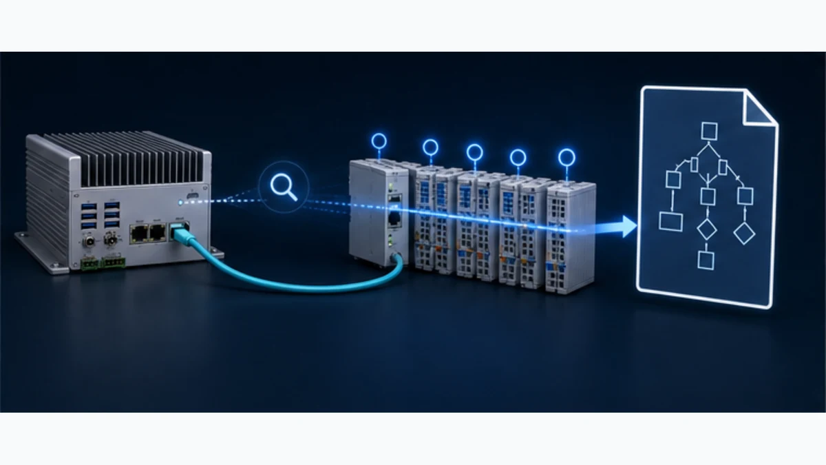
The current Bus tab lists devices discovered on the selected interface by physical position, vendor ID and product code. A scanned row marked No XML means the runtime saw a SubDevice but the editor repository has no matching ESI XML for the vendor/product/revision. Download the current ESI from the device manufacturer, record its source/version/checksum, import it into the repository, and scan again.
ESI is not optional decoration. EtherCAT Technology Group defines it as the XML device description containing network-accessible properties, process-data mapping options, mailbox protocols and synchronization modes. A device with the same marketing name but another product code or revision may expose different PDOs or startup behavior. Do not defeat identity checks merely to reach OP.
| Scan or repository symptom | Meaning | Correct evidence action |
|---|---|---|
| expected devices in exact physical order | link and enumeration are plausible | compare count, position, vendor ID, product code and revision with the bill of materials |
| first device absent | wrong NIC, no link/power or cable connected to wrong port | inspect selected interface, link, power and first SubDevice IN port |
| downstream devices absent | break/power/device problem after last visible position | inspect the segment between the last visible and first missing device |
| No XML | physical device found but no matching ESI entry | obtain manufacturer ESI for exact identity and re-add after import |
| project order differs from scan | physical construction or offline project changed | reconcile under change control; do not accept an accidental reorder |
| replacement remains mismatched | product/revision/PDO/startup behavior differs | restore the approved part/revision or approve a new interface version |
The editor can also add a device from the repository before hardware is available. That is useful for offline planning, but it does not prove the physical chain. At commissioning, compare the offline order to a live scan. Removing a configured device removes its mappings; retain a project backup before structural changes.
Map PDO channels to IEC 61131-3 variables
Understand direction from the SubDevice perspective
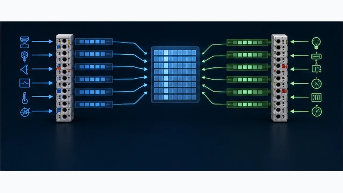
EtherCAT PDO direction is frequently reversed in conversation. TxPDO is transmitted by the SubDevice and becomes an input to the controller. RxPDO is received by the SubDevice and carries controller outputs. Current OpenPLC editor documentation displays TxPDO-derived channels as inputs and RxPDO-derived channels as outputs, then assigns suitable located addresses such as %IX, %QX, %IW and %QW.
The current editor can pre-assign addresses while avoiding collisions with other EtherCAT and remote-device mappings. That prevents a simple duplicate, but it cannot decide application meaning. Rename aliases, create typed semantic variables at the application boundary, document scale and preserve quality/freshness. Never scatter raw %IW7 references across logic without a versioned map.
| Process item | EtherCAT view | OpenPLC view | Acceptance proof |
|---|---|---|---|
| digital input | one SubDevice TxPDO bit | %IXbyte.bit or mapped BOOL |
actuate one approved channel; prove raw and semantic state |
| digital output | one SubDevice RxPDO bit | %QXbyte.bit or mapped BOOL |
output remains inhibited until quality and permissives pass |
| 16-bit analog input | TxPDO entry | %IWn, INT/UINT/WORD as declared |
test low/mid/high and fault code; verify signedness/scale |
| 32-bit setpoint | RxPDO entry | %QDn, DINT/UDINT/REAL as declared |
use asymmetric hexadecimal patterns and safe bounded command |
| drive status word | TxPDO bitfield | WORD plus decoded state | compare every relevant bit to exact drive profile/manual |
| drive control word | RxPDO bitfield | WORD produced by reviewed sequencer | prove state transitions, timeout and command removal |
| application heartbeat | selected cyclic field | counter plus age timer | stop producer and prove stale data is rejected |
Keep a human-readable mapping contract
| Field | Required record |
|---|---|
| identity | bus, physical position, vendor ID, product code, revision and ESI filename/checksum |
| PDO entry | Tx/Rx PDO, index/subindex where exposed, bit length and direction |
| IEC binding | located address, IEC type, alias and consuming/producing program |
| semantics | process name, engineering unit, scale, valid range, enumerations and reserved values |
| quality | device state, working-counter/configuration condition, freshness and substitute behavior |
| command ownership | mode, permissive, accepted/active/complete/fault handshake and reset ownership |
| interface version | major/minor mapping revision and compatible controller/device project versions |
Use known non-symmetric patterns to expose byte order and type errors: 16#0001, 16#0100, 16#7FFF, 16#8000, 16#FFFF, and known IEEE-754 values when REAL is genuinely declared. Observe the ESI/channel model, runtime raw image and application variable. Do not “fix” an unexplained value by multiplying or swapping until the exact boundary is identified.
Configure cycle time, task relationship, watchdog and Distributed Clocks
Start conservatively and measure
Current editor documentation gives an EtherCAT bus cycle range of 100 to 100000 microseconds with a 1000-microsecond default. That UI range is not a guarantee that an arbitrary host can sustain 100 microseconds, nor that a device application needs it. Select a starting cycle from device requirements, network size, host capability and application task. Measure under representative CPU, I/O, logging and communication load.
The PLC task and EtherCAT exchange are related but not automatically identical. If the bus updates every 1 ms while application logic runs every 20 ms, the application consumes only one of many samples. If application logic expects new data faster than the bus produces it, repeated values are normal. Document sampling, output update, end-to-end age and timeout semantics.
| Timing setting | Design question | Evidence |
|---|---|---|
| bus cycle | how often should cyclic frames exchange for this device set? | measured cycle/jitter and device OP stability under load |
| IEC task interval | how often should the application consume/produce mapped values? | task trace and worst execution time below interval with margin |
| plugin task priority | what host scheduler/priority is actually granted? | running policy/priority, CPU/IRQ placement and overrun record |
| watchdog cycles | how many missed exchanges trigger the configured reaction? | calculated time plus injected missed-cycle test |
| application stale timer | when is a value too old for the process? | heartbeat/age test independent of link state |
| Distributed Clocks | which devices/mode/reference clock need synchronization? | exact ESI/device support, DC status and measured synchronization |
Do not label an ordinary OpenPLC EtherCAT project “hard real time” because a priority field exists. Determinism is a measured property of the complete host, kernel, driver, NIC, plugin, device line, cycle configuration and workload. Do not label a fast ordinary process-data watchdog a safety function. Safety over EtherCAT requires an independently selected, certified and validated FSoE architecture where applicable; normal OpenPLC process data does not create it.
Configure startup parameters and state transitions
Treat INIT, PREOP, SAFEOP and OP as diagnostic gates
EtherCAT SubDevices move through a defined Application Layer state machine. INIT provides basic register access. PREOP enables mailbox configuration where supported. SAFEOP establishes input process data while outputs remain in their safe behavior. OP enables the configured output process data. The MainDevice requests transitions; the SubDevice reports state and status.
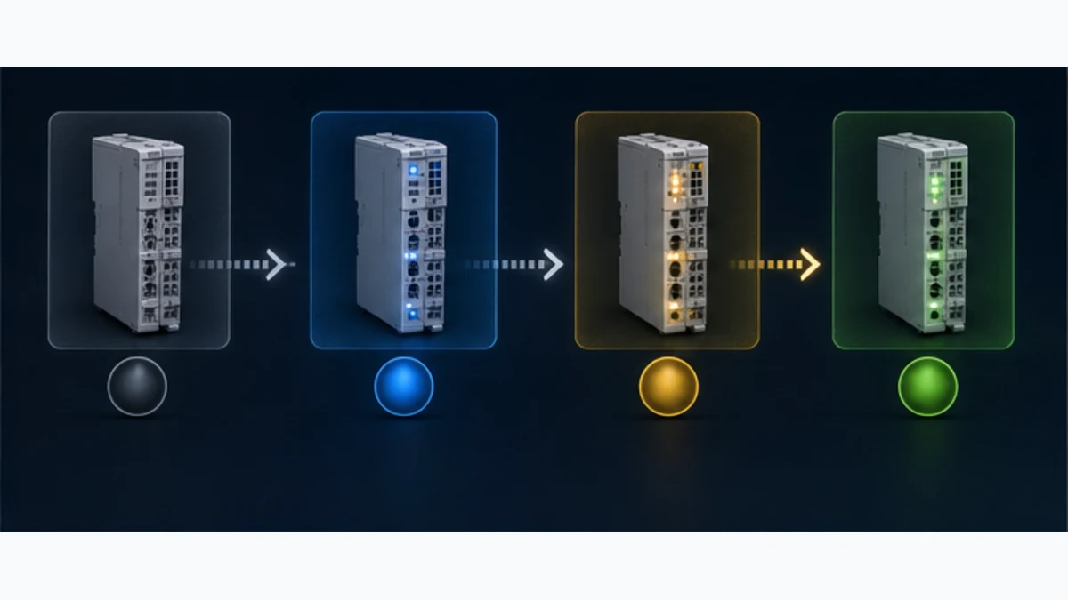
| Stopped state | First interpretation | First proofs |
|---|---|---|
| INIT | MainDevice cannot establish expected basic device/configuration path | link/order, identity, ESI/configuration and AL status |
| PREOP | mailbox/startup configuration or identity mismatch | exact SDO index/subindex/abort, ESI revision and startup list |
| SAFEOP | PDO/SyncManager/DC/watchdog/output readiness mismatch | expected process image, AL status, DC config and device manual |
| OP with wrong values | transport state passed but data contract is wrong | raw PDO, IEC address/type, byte order, scale and application quality |
| OP oscillates/recovering | intermittent physical/timing/WKC/configuration problem | WKC history, link/error counters, first affected position and host overruns |
Current OpenPLC troubleshooting guidance says a MainDevice stuck in PRE-OP commonly indicates an ESI revision mismatch and SAFE-OP failure can follow a rejected startup SDO. Preserve the actual runtime log: object index/subindex, abort or AL status, device position and time. Do not remove every startup write until the bus reaches OP; that can hide a required parameter and move the failure into application behavior.
Commission OpenPLC EtherCAT in evidence gates
| Gate | Test | Pass condition |
|---|---|---|
| 1. release set | compare editor, runtime, plugin, OS, NIC, ESI and device firmware | exact supported/tested bundle is archived |
| 2. safe construction | inspect dedicated NIC, direct first link, SubDevice order, power and approved machine state | physical system matches drawing with outputs independently inhibited |
| 3. discovery | scan the dedicated interface | expected count/order/vendor/product/revision appears once |
| 4. ESI match | import manufacturer files and add devices | no unexplained No XML or identity mismatch remains |
| 5. state sequence | start bus with application commands disabled | every required device reaches intended state with recorded AL status |
| 6. input mapping | actuate known non-hazardous inputs | raw channel, located variable and semantic variable agree |
| 7. output mapping | use approved bounded test mode | correct channel changes only after quality/permissives and returns safe |
| 8. type/scale | apply boundary/asymmetric values | sign, order, scale, range and fault values pass |
| 9. timing | load host and fieldbus representatively | cycle, jitter, WKC and task execution retain requirement-derived margin |
| 10. fault/recovery | break one defined boundary at a time | stale quality, safe response, alarm, retained evidence and deliberate recovery pass |
| 11. restart/restore | reboot/replace where approved | plugin, interface, ESI, mapping and disabled command state restore deterministically |
An OP master state is not the final acceptance criterion. Prove the actuator or process feedback, command ownership, failure response and restart prevention under the approved site procedure. Do not force outputs or connect/disconnect a live machine merely to complete a tutorial.
Troubleshoot by the first failed boundary
Use working counter as a consistency alarm, not a root cause
EtherCAT appends a Working Counter to each datagram. Addressed SubDevices increment it when the addressed memory operation is processed. The MainDevice knows the expected value and can detect inconsistent cyclic exchange. EtherCAT Technology Group emphasizes that a wrong WKC is a digital symptom, not a unique cause: missing/unreached devices, resets, non-OP states and other conditions can all produce it.
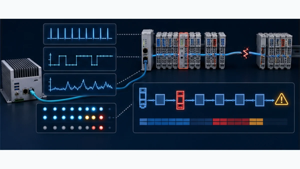
| Symptom | First discriminating evidence | Likely boundary | Avoid |
|---|---|---|---|
| EtherCAT option absent | editor build, connected target and runtime capabilities | wrong editor/target/generation | reinstalling ESI files |
| discovery unavailable | v4 runtime version, plugin/service and dedicated NIC assignment | runtime/plugin/host | editing PDO mappings |
| no devices found | selected NIC/link, first IN port and SubDevice power | physical/interface | changing cycle time |
| No XML | scanned vendor/product/revision versus repository | ESI identity | importing an unrelated family XML |
| stuck PREOP | exact ESI/revision and failed startup/mailbox status | identity/startup | disabling identity checks |
| stuck SAFEOP | AL status, PDO/SyncManager, SDO and DC settings | process configuration/timing | forcing OP repeatedly |
| OP but WKC mismatch | expected/actual WKC, states, first missing device and port errors | physical/reset/state/timing | treating OP badge as healthy |
| values frozen | WKC/state plus heartbeat/data-age and raw PDO | application quality/mapping | accepting last value as live |
| value wrong | known raw pattern, direction, IEC type, byte/word order and scale | data contract | arbitrary swap/multiplier |
| cycle overrun | runtime timing log, CPU/IRQ/workload and configured cycle | host scheduling/load | only raising priority |
| outputs act after reconnect | stale command, enable/permissive and recovery-state logic | application restart design | increasing watchdog until symptom disappears |
Preserve the first failure
Before restart, export or capture runtime version, plugin status, configured interface, device count/order, MainDevice state, each SubDevice state/AL status, expected and actual WKC, cycle/overrun statistics, link/error counters, first failed startup SDO, raw mapped values, application data age and the time of the physical event. Correlate clocks. A reset may recover operation while destroying the cause.
Packet capture on EtherCAT requires an approved topology and qualified method. Inserting a normal switch, long tap lead or uncontrolled adapter can change or break the network. Use supported diagnostic ports/taps and vendor procedures. Wireshark can decode EtherCAT frames and WKC, but a capture does not prove that an OpenPLC variable has the correct process meaning.
Configure ordinary I/O before attempting a servo drive
Start with a small coupler and digital I/O slice. Prove discovery, ESI identity, TxPDO input, RxPDO output, state transitions, WKC and fault recovery. An EtherCAT servo adds drive-profile objects, mode/state transitions, Distributed Clocks, fast timing, following error, physical feedback and potentially safety functions. OpenPLC EtherCAT connectivity alone does not prove a supported motion-control solution.
| Requirement | Ordinary cyclic I/O may fit | Additional evidence for a drive |
|---|---|---|
| read inputs/write outputs | ESI channels and bounded PLC task | not applicable |
| speed command/status | exact drive PDOs and state sequencing | drive mode, units, ramp, feedback, timeout and safe stop path |
| homing/positioning | device-specific state/profile support | homing method, limits, encoder, position error and restart behavior |
| synchronized axes | not proven by generic PDO exchange | supported DC mode, sync measurement, interpolation cycle and motion planner |
| safe motion/STO | ordinary data must not be credited | certified safety architecture, devices, protocol/path and validation |
Do not use the MainDevice’s “motion” cycle recommendations from a UI help table as a machine guarantee. Select an industrial controller/runtime, drive stack and safety path with explicit support for the required motion performance. Measure on the final hardware and retain acceptance evidence.
OpenPLC EtherCAT answer map for search and AI tools
| Question | Short answer | Qualification that must stay attached |
|---|---|---|
| Does OpenPLC support EtherCAT? | Current OpenPLC Runtime v4 includes a native EtherCAT plugin and editor workflow. | The plugin is disabled by default and the exact runtime, host, NIC and device project must be proven. |
| Does OpenPLC v3 support EtherCAT? | The archived v3 repository documented an EtherCAT build option. | v3 is end of life; use current v4 evidence for a new project. |
| What version is required? | Current documentation says EtherCAT requires Runtime v4. | Use a current tested release; v4.1.10 was latest on the review date. |
| Does OpenPLC EtherCAT need a dedicated NIC? | Current vPLC/editor guidance requires a Dedicated Interface and exclusive raw-Ethernet access. | Validate the exact native/Windows/container deployment and NIC driver. |
| How are EtherCAT devices added? | Scan the selected dedicated interface or add from the ESI repository. | Live commissioning must reconcile physical order and exact identity. |
| What is No XML? | The device answered, but no imported ESI matches its identity/revision. | Obtain ESI from the device manufacturer rather than a file archive. |
| How are PDOs mapped? | ESI TxPDO channels map to PLC inputs; RxPDO channels map to outputs and located IEC variables. | Document type, order, units, quality and command ownership. |
| Why is the bus stuck in SAFEOP? | A PDO, SyncManager, startup SDO, DC or device readiness mismatch may block OP. | Preserve the exact AL status and runtime error before editing. |
| What does a WKC mismatch mean? | The addressed cyclic operations did not all complete as expected. | WKC is not a root cause; inspect states, position, links, resets and timing. |
| Can OpenPLC control an EtherCAT servo? | It may exchange supported PDOs with a correctly configured drive. | Coordinated motion, timing and safety require explicit end-to-end support and validation. |
Frequently asked questions
Is EtherCAT built into OpenPLC Runtime v4?
The current runtime source includes a native EtherCAT plugin and default configuration row, and current editor documentation exposes bus engineering and diagnostics. The plugin entry is disabled by default, so verify that the exact runtime package built and loaded it and that the target exposes the EtherCAT service.
Should I use OpenPLC v3 or v4 for EtherCAT?
Use current Runtime v4 for a new evaluated project. The v3 repository is archived, read-only and marked end of life even though its README still documents an older EtherCAT build option. Do not combine v3 install commands with v4 plugin/editor instructions.
Why is the OpenPLC EtherCAT Scan button disabled?
Current troubleshooting guidance checks three boundaries: the editor must be connected to Runtime v4, a network interface must be selected, and the discovery service must be available. For a managed vPLC, the EtherCAT NIC must have been assigned as a Dedicated Interface.
Can OpenPLC EtherCAT share the management Ethernet port?
Do not design it that way. Current editor guidance calls for a dedicated NIC and warns that management traffic can cause intermittent working-counter faults. Keep editor/runtime management on another interface and document the exclusive fieldbus port.
Where do OpenPLC EtherCAT ESI files come from?
Obtain ESI XML from the exact SubDevice manufacturer/product source. Record its version and checksum. Match vendor ID, product code and revision. A No XML scan result proves discovery but not a valid device model.
What is TxPDO versus RxPDO in OpenPLC?
Direction is named from the SubDevice: TxPDO data travels from the SubDevice into OpenPLC inputs; RxPDO data travels from OpenPLC outputs to the SubDevice. Confirm the editor mapping and actual device manual before commands are enabled.
Why does OpenPLC EtherCAT stop in PREOP or SAFEOP?
PREOP commonly points to identity, ESI or mailbox/startup configuration. SAFEOP commonly points to PDO/SyncManager, Distributed Clock, startup SDO or output-readiness problems. Use the exact AL status and runtime log rather than repeatedly requesting OP.
What causes an OpenPLC EtherCAT WKC mismatch?
A different working counter means not all expected datagram memory operations completed. Missing/unreached devices, a reset, a non-OP state, physical errors or timing problems are candidates. Correlate the first failed position, state, links, counters and host overruns.
Can I run OpenPLC EtherCAT in Docker?
A container can package the runtime, but an ordinary Docker bridge does not become an EtherCAT interface. The host must expose the correct raw dedicated NIC and required capabilities through a documented, secured deployment. Validate timing and recovery on the actual host and network.
Can a browser simulator validate OpenPLC EtherCAT hardware?
No. A browser lab can teach state, mapping, quality and layered fault diagnosis. It cannot validate the v4 plugin, host scheduler, NIC, ESI, device firmware, physical topology, cycle jitter, drive motion or safety response. Repeat every acceptance test on the approved representative system.
Sources, review scope and limitations
This guide was reviewed on August 30, 2026. OpenPLC releases, editor surfaces, hosted products, package contents, plugins and documentation can change quickly. Pin and retest the exact release set. Product/device manuals and the site’s approved control/safety lifecycle govern an installed machine.
- OpenPLC Runtime v4.1.10 latest release — Autonomy Logic on GitHub
- OpenPLC Runtime v4 architecture, install and plugin overview — Autonomy Logic
- Default plugin configuration including the disabled EtherCAT native-plugin row — Autonomy Logic
- Runtime installer and native plugin/SOEM build workflow — Autonomy Logic
- OpenPLC v4 plugin architecture and native plugin lifecycle — Autonomy Logic
- Archived OpenPLC v3 repository and EtherCAT/EOL generation boundary — OpenPLC Project
- OpenPLC EtherCAT Bus tab, dedicated NIC, scan and ESI matching — Autonomy Logic
- OpenPLC EtherCAT Channel Mappings and IEC located variables — Autonomy Logic
- OpenPLC EtherCAT Device Info and exact identity/revision evidence — Autonomy Logic
- OpenPLC EtherCAT Advanced cycle, priority and watchdog settings — Autonomy Logic
- OpenPLC EtherCAT runtime diagnostics — Autonomy Logic
- OpenPLC EtherCAT troubleshooting, state and working-counter symptoms — Autonomy Logic
- EtherCAT technology, ESI, working counter and diagnosis principles — EtherCAT Technology Group
- ETG.2200 EtherCAT implementation guide and state-machine context — EtherCAT Technology Group
- EtherCAT Diagnosis for Users and working-counter limits — EtherCAT Technology Group
- OpenPLC Runtime security considerations for images, privileges, logs and volumes — Autonomy Logic
The six figures are original conceptual editorial illustrations generated for this guide. They are not OpenPLC or EtherCAT product drawings, software screenshots, approved topologies, pinouts, waveform limits, status-code references, conformance results or safety designs. OpenPLC is an Autonomy Logic/OpenPLC Project name. EtherCAT is a registered trademark and patented technology licensed by Beckhoff Automation GmbH, Germany. This independent educational page is not an official vendor publication.
This guide does not authorize connecting/disconnecting an energized fieldbus, changing host privileges or network security, loading a runtime/plugin/project, forcing I/O, commanding a drive, bypassing a safeguard or energizing machinery. Only qualified and authorized personnel following the site risk assessment, hazardous-energy and electrical safe-work programs, approved change/rollback plan, validated safety lifecycle and exact manufacturer instructions should work on an installed system. Ordinary EtherCAT/OpenPLC data and watchdogs are not safety functions.
Now run it · free · no signup
Practise the logic before you set up OpenPLC
Run motor, timer and counter logic in your browser with nothing to install, then rebuild it in OpenPLC. Free to try — no signup.
Ownership disclosure: PLC Programming IO and PLC Simulation Software are operated by the same publisher.
PLC Programming IO Editorial Team
Industrial automation education, references, and software testing
The PLC Programming IO Editorial Team publishes sourced industrial-automation education and documents how material is reviewed, tested, and corrected. A team byline means the publisher is responsible for the page; it does not represent a fictional person or imply an engineering licence.
Coverage:
- • PLC programming concepts and examples
- • Vendor software tutorials and comparisons
- • SCADA, HMI, protocols, and instrumentation
- • Training, careers, and reference material
Review standard:
- • Prefer primary and official sources
- • Record software versions when material
- • Separate tested facts from estimates
- • Publish material corrections
Important scope note
This site provides education, not project-specific engineering approval. Safety, code, and compliance decisions require a qualified person with access to the actual machine and jurisdiction.