Modbus RTU Tutorial: RS-485 Wiring, Frames & CRC
Implement Modbus RTU with the official serial-line model: RS-485 trunk wiring, termination, timing, addressing, function codes, CRC checks, PLC examples, and diagnostics.
Introduction: Master Modbus RTU Protocol for Industrial Automation
Modbus RTU is a common serial protocol in manufacturing, process control, building automation and energy applications. This guide focuses on implementing and diagnosing the published protocol rather than making an unsupported estimate of its installed base.
Developed for Modicon controllers in 1979, Modbus remains available through open specifications maintained by the Modbus Organization. Many PLCs, drives and instruments implement it, but function codes, register maps and electrical details vary by device; verify each endpoint manual.
This comprehensive Modbus RTU protocol tutorial covers everything from fundamental concepts to advanced implementation techniques. You'll learn frame structure details, function code operations, RS-485 wiring practices, PLC configuration procedures, and troubleshooting methods that professional automation engineers use to create robust Modbus RTU communication networks.
The Modbus protocol family includes three variants: Modbus RTU for serial communication using binary encoding, Modbus ASCII for serial communication using ASCII encoding, and Modbus TCP/IP for Ethernet networks. This guide focuses specifically on Modbus RTU, the most common variant for serial industrial communications.
Chapter 1: Understanding Modbus RTU Fundamentals
What is Modbus RTU Protocol?
Modbus RTU (Remote Terminal Unit) is a serial communication protocol that uses binary encoding to transmit data between master and slave devices over RS-232, RS-422, or RS-485 networks. The protocol defines message structure, data formats, error checking methods, and communication rules that ensure reliable data exchange in industrial environments.
Key Characteristics of Modbus RTU:
- Binary Encoding: Compact message format using 8-bit binary values
- Master/Slave Architecture: Single master controls communication with multiple slaves
- Function Code Based: Standardized commands for read/write operations
- CRC Error Checking: 16-bit cyclic redundancy check ensures data integrity
- Simple Implementation: Minimal processing requirements for embedded systems
- Vendor Neutral Specification: Implemented by devices from many automation vendors; confirm the exact model
Modbus RTU History and Evolution
Origins (1979): Modicon developed Modbus as a simple protocol for its PLC products, initially using RS-232 serial communication for point-to-point connections. The protocol's design prioritized simplicity and reliability over advanced features or high-speed performance.
Standardization (1999-2004): Schneider Electric transferred ownership to the Modbus Organization, which published open specifications and established conformance testing procedures. This transition ensured Modbus remained vendor-neutral and freely available for implementation.
Modern Applications: Today, Modbus RTU remains available in many sensors, drives, meters, PLCs, gateways, and SCADA interfaces. Its presence and supported functions are product-specific, so verify the exact model and firmware.
Why Modbus RTU Remains Industry Standard
Universal Compatibility: Virtually every PLC, HMI, SCADA system, and industrial device supports Modbus RTU communication, ensuring easy integration between equipment from different manufacturers without proprietary protocols or special adapters.
Mature and diagnosable: The frame format and CRC are well documented, which makes the protocol practical to inspect with a serial analyzer. Reliable operation still depends on cable, topology, termination, biasing, grounding, baud rate and device implementation.
Low Implementation Cost: Simple hardware requirements, royalty-free licensing, and extensive documentation reduce implementation costs while providing performance sufficient for most industrial applications. Standard RS-485 transceivers and basic microcontrollers can implement complete Modbus RTU stacks.
Extensive Support Resources: Abundant training materials, troubleshooting guides, diagnostic tools, and technical expertise make Modbus RTU accessible to automation professionals at all experience levels.
Modbus Protocol Comparison
| Feature | Modbus RTU | Modbus ASCII | Modbus TCP |
|---|---|---|---|
| Physical Layer | RS-232/RS-485 | RS-232/RS-485 | Ethernet TCP/IP |
| Encoding | Binary (8-bit) | ASCII (7-bit) | Binary (8-bit) |
| Message Size | Compact | ~2x larger | Compact + TCP overhead |
| Error Checking | CRC-16 | LRC (1 byte) | TCP checksums |
| Speed | Device and serial-line dependent | Device and serial-line dependent | Network and device dependent |
| Distance | Physical-layer, cable, data-rate and installation dependent | Physical-layer, cable, data-rate and installation dependent | Ethernet medium and topology dependent |
| Addressing | Serial addresses 1–247; electrical segment limit is separate | Serial addresses 1–247; electrical segment limit is separate | Unit identifier and endpoint implementation dependent |
| Best For | Serial networks | Legacy systems | Modern Ethernet |
| Efficiency | High | Moderate | High |
When to Use Modbus RTU:
- Serial communication required (no Ethernet infrastructure)
- Serial links whose tested distance and data rate fit the selected EIA/TIA-485 implementation
- Simple point-to-point or multi-drop networks
- Integration with legacy serial devices
- Cost-sensitive applications
- Installations where an engineered differential serial link meets the EMC and grounding requirements
When to Consider Alternatives:
- High-speed data requirements exceed serial capabilities
- Existing Ethernet infrastructure available
- Need for more than 247 nodes on single network
- Advanced diagnostics and security features required
Chapter 2: How Modbus RTU Communication Works

Master/Slave Architecture Explained
Master Device Role: The Modbus RTU master initiates all communication on the network, sending requests to specific slave devices and waiting for responses. Only one master can control the network at any time, preventing message collisions and ensuring deterministic communication behavior.
Slave Device Role: Slave devices listen continuously for messages addressed to their unique slave ID, respond when queried by the master, and never initiate communication independently. This passive behavior ensures predictable network timing and prevents communication conflicts.
Network Topology: Modbus RTU typically uses multi-drop topology where one master connects to multiple slaves through a shared communication bus. Each slave requires a unique address (1-247), with address 0 reserved for broadcast messages that all slaves receive but don't respond to.
Request/Response Communication Model
Communication Flow:
- Master sends request message to specific slave address
- Slave receives message and validates CRC checksum
- Slave processes request and prepares response data
- Slave sends response message back to master
- Master validates response CRC and processes data
- Master proceeds to next transaction after appropriate delay
Transaction Timing: Each transaction requires specific timing intervals to ensure reliable communication. Masters must wait for slave responses before sending new requests, and proper silent intervals between messages prevent data corruption.
Half-Duplex Operation: RS-485 networks operate in half-duplex mode, meaning only one device transmits at any time while others listen. This requires careful timing management and proper bus arbitration to prevent message collisions.
Modbus RTU Timing Requirements
Silent Interval (3.5 Character Times): Modbus RTU uses silent intervals of at least 3.5 character times to mark message boundaries. This silence ensures receivers can distinguish separate messages and synchronize frame decoding properly.
Character Time Calculation: Character time depends on baud rate and includes start bit, 8 data bits, parity bit (if used), and stop bit(s):
- At 9600 baud: 1 character ≈ 1.146 ms, 3.5 characters ≈ 4.0 ms
- At 19200 baud: 1 character ≈ 0.573 ms, 3.5 characters ≈ 2.0 ms
- At 115200 baud: 1 character ≈ 0.096 ms, 3.5 characters ≈ 0.33 ms
Response Timeout: The master needs a timeout for a missing response. Derive it from request and response transmission time, device processing time, gateway delay, turnaround behavior, and the required retry policy. Measure the slowest supported device state instead of copying a generic range.
Inter-Frame Delay: Some devices require additional delay between transactions to process requests. This delay varies by device and should be documented in device specifications.
Communication Flow Example
Reading Holding Registers Transaction:
Master Query:
[0x01] [0x03] [0x00 0x00] [0x00 0x02] [CRC]
Device  Read    Start      Quantity    Check
ID=1   Holding  Address    2 Registers
       Regs    0

Slave Response:
[0x01] [0x03] [0x04] [0x12 0x34] [0x56 0x78] [CRC]
Device  Read   Byte   Register   Register   Check
ID=1   Holding Count  0 Value    1 Value
       Regs   4 bytes
Communication Steps:
- Master sends query after 3.5 character silence
- Slave ID 1 recognizes its address
- Slave validates CRC and processes function code
- Slave reads requested registers and formats response
- Slave sends response with data and CRC
- Master validates response and extracts register values
- Master waits 3.5 character times before next transaction
Chapter 3: RS-485 Physical Layer Implementation
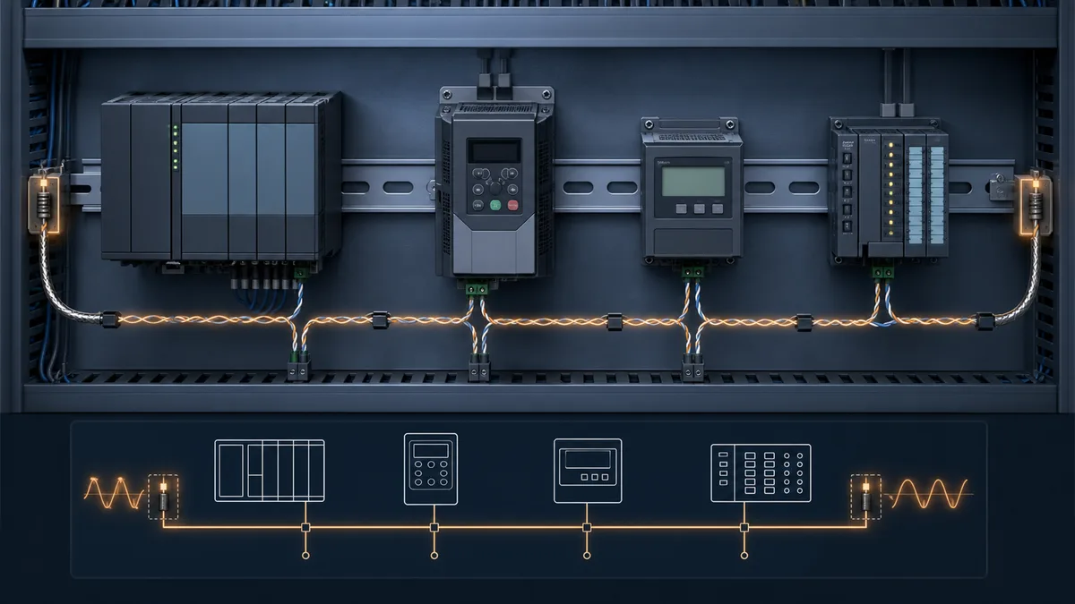

Understanding RS-485 Serial Communication
RS-485 Electrical Characteristics: RS-485 defines differential signaling using two wires (A and B) to transmit data, providing excellent noise immunity and long-distance capability. Voltage differences between A and B lines represent data bits, with typical voltage swings of ±1.5V to ±6V.
Key RS-485 Advantages:
- Multi-drop Capability: 32 full unit loads is the conservative baseline; higher node counts require fractional-unit-load transceivers and device documentation
- Cable Length: Depends on baud rate, cable impedance/capacitance, topology, load count, termination and installation noise—do not apply one universal maximum
- High Noise Immunity: Differential signaling rejects common-mode noise
- Flexible Topology: Supports point-to-point, multi-drop, and repeater networks
- Cost Effective: Simple transceiver chips and standard twisted-pair cabling
RS-485 Wiring Configurations
Two-Wire Half-Duplex (Most Common): Uses single twisted-pair for bidirectional communication:
- The two data conductors using the polarity names printed in each device manual
- Optional signal ground reference
- Signal-reference and shield/drain conductors installed according to the device and site EMC design
Four-Wire Full-Duplex (Point-to-Point): Uses separate twisted-pairs for transmit and receive:
- TX+ / TX- for transmit direction
- RX+ / RX- for receive direction
- Enables simultaneous bidirectional communication
- Limited to point-to-point applications
Wiring Best Practices:
- Use the cable type and characteristic impedance required by the installed transceivers and vendor guide
- Maintain consistent polarity throughout network
- Keep cable runs straight without stubs or branches
- Minimize cable length and number of nodes
- Terminate shields according to the cable, device, and EMC design; do not apply a universal one-end rule
Network Termination Requirements
Why Termination is Critical: Without proper termination, signal reflections at cable ends cause waveform distortion, increased error rates, and communication failures, especially at higher baud rates or longer cable lengths.
Termination Resistor Selection:
- Match the installed cable and transceiver guidance; 120 Ω is common but not universal
- Verify resistance, tolerance, and power rating from the network design
- Terminate only the two physical ends of a trunk unless the product documentation specifies another supported topology
- Confirm whether the endpoint already contains switchable or fixed termination before adding an external resistor
Termination Methods:
- Passive Termination: 120Ω resistor at each cable end
- Biased Termination: 120Ω resistor plus bias resistors (failsafe)
- Active Termination: Powered circuitry maintaining idle state
- Switchable Termination: DIP switches for flexible configuration
Biased Termination Circuit:
     +5V
      |
    620Ω (pull-up to A)
      |
      A----[120Ω]----B
                     |
                   620Ω (pull-down from B)
                     |
                    GND
Biased termination ensures defined idle state when no devices drive the bus, preventing false triggering and improving noise immunity.
Cable Specifications and Distance
Recommended Cable Types:
- Belden 3105A (24 AWG, 120Ω impedance)
- Alpha Wire 6173 (22 AWG, low capacitance)
- General purpose 22-24 AWG twisted-pair
- Category 5/6 Ethernet cable (for short runs)
Distance vs. Baud Rate Guidelines:
| Baud Rate | Maximum Distance | Typical Application |
|---|---|---|
| 9600 | 1,200m (4,000 ft) | Large facilities |
| 19200 | 1,200m (4,000 ft) | Standard networks |
| 38400 | 1,000m (3,300 ft) | Medium distances |
| 57600 | 800m (2,600 ft) | Shorter runs |
| 115200 | 500m (1,650 ft) | High-speed local |
Extending Network Distance:
- RS-485 repeaters regenerate signals (up to 10,000m total)
- Fiber optic converters for extreme distances
- Multiple segments with proper isolation
- High-quality cable reduces attenuation
Grounding and Shielding Best Practices
Signal Ground Reference: Connect signal ground (common) wire between all nodes to provide voltage reference. This prevents ground potential differences from creating common-mode voltage that exceeds input limits.
Shield Grounding:
- Terminate the cable shield according to the endpoint manuals and site EMC design
- Grounding at multiple points creates ground loops
- Ground loops cause circulating currents and noise injection
- Use drain wire connected to earth ground through chassis
Isolation Considerations:
- Isolated transceivers prevent ground loops
- Optical isolation protects against voltage differences
- Isolated power supplies reduce common-mode noise
- Surge protection devices guard against transients
Chapter 4: Modbus RTU Frame Structure Deep Dive
Complete Frame Breakdown
Every Modbus RTU message consists of five essential components transmitted as continuous binary stream without gaps:
┌─────────────────────────────────────────────────────────┐
│ Silence │ Address │ Function │ Data │ CRC-16 │ Silence │
│  3.5t   │ 1 byte  │  1 byte  │ N bytes │ 2 bytes │  3.5t  │
└─────────────────────────────────────────────────────────┘
Frame Component Details:
- Silent Interval (3.5 character times): Message start marker
- Slave Address (1 byte): Device ID (1-247), 0 for broadcast
- Function Code (1 byte): Command type (1-127 valid, 128+ error)
- Data Field (0-252 bytes): Function-specific parameters and values
- CRC-16 (2 bytes): Error checking value (low byte first)
- Silent Interval (3.5 character times): Message end marker
Slave Address Field
Valid Address Range:
- 1-247: Individual slave addresses
- 0: Broadcast address (all slaves execute, none respond)
- 248-255: Reserved for future use
Address Assignment Strategy: Document and label all device addresses clearly to facilitate troubleshooting and maintenance. Many organizations use address ranges by device type or physical location.
Broadcast Operations: Broadcast messages (address 0) enable simultaneous write operations to all slaves but don't generate responses, making them suitable for synchronized actions but unsuitable for read operations.
Function Code Field
Function codes define the operation type and expected data format. Standard function codes (1-64) are defined by Modbus specification, while user-defined codes (65-72 and 100-110) allow custom implementations.
Function Code Categories:
- Bit Access: Read/write individual bits (coils and discrete inputs)
- Word Access: Read/write 16-bit registers
- File Record Access: Read/write file records (rarely used)
- Diagnostics: Network testing and troubleshooting
- Exception Responses: Error indication (function code + 0x80)
Data Field Structure
Request Data: Contains function-specific parameters such as starting addresses, quantity of points, and values to write. Data format varies by function code but always uses big-endian byte order.
Response Data: Contains requested data, status information, or error codes. Response format depends on request function code and operation success.
Data Limits: Maximum frame size of 256 bytes limits data field to 252 bytes (256 - address - function - CRC), restricting maximum registers per transaction to 125 for read operations.
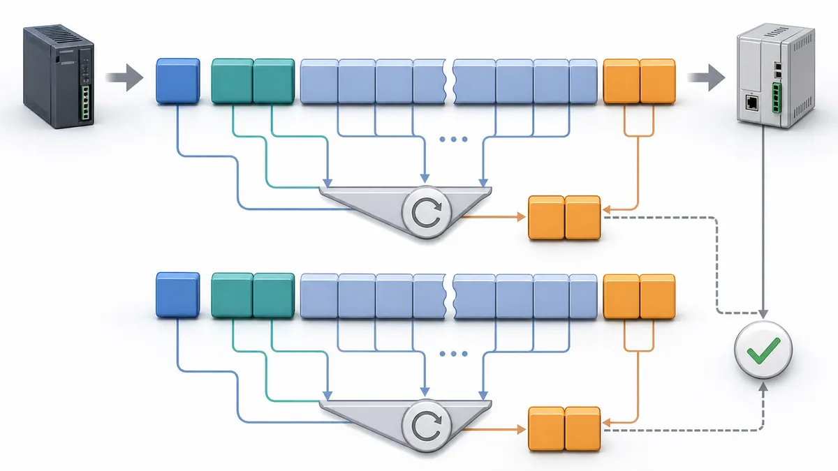
CRC-16 Error Checking
Purpose: 16-bit Cyclic Redundancy Check detects transmission errors including single-bit errors, double-bit errors, odd number of bit errors, and burst errors up to 16 bits long.
CRC Calculation Process:
- Initialize 16-bit register to 0xFFFF
- XOR first data byte with low byte of register
- Shift register right one bit
- If LSB was 1, XOR register with 0xA001
- Repeat steps 3-4 eight times for each byte
- Process all bytes (address, function, data)
- Resulting register value is CRC (low byte transmitted first)
CRC Example Code (Pseudo-code):
function CalculateCRC(data[], length):
    crc = 0xFFFF

    for i = 0 to length-1:
        crc = crc XOR data[i]

        for j = 0 to 7:
            if (crc AND 0x0001):
                crc = (crc >> 1) XOR 0xA001
            else:
                crc = crc >> 1

    return crc  // Low byte first, then high byte
CRC Verification: Receivers calculate CRC on received bytes and compare with transmitted CRC. Mismatches indicate transmission errors and trigger message rejection without response.
Chapter 5: Modbus RTU Function Codes Complete Reference
Read Coils (Function Code 01)
Purpose: Read status of discrete output coils (binary outputs)
Request Format:
[Slave ID] [0x01] [Start Address Hi] [Start Address Lo]
[Quantity Hi] [Quantity Lo] [CRC Lo] [CRC Hi]
Example - Read 10 coils starting at address 0x0014:
Request:  0x01 0x01 0x00 0x14 0x00 0x0A [CRC]
Response: 0x01 0x01 0x02 0xCD 0x01 [CRC]
          (Byte count=2, Data=0x01CD = bits status)
Coil Status Encoding: Bit 0 of first byte = coil at start address, bit 1 = next coil, etc. Each byte contains 8 coil states with unused high-order bits set to 0.
Read Discrete Inputs (Function Code 02)
Purpose: Read status of discrete inputs (binary inputs)
Request Format: Identical to Read Coils (Function 01) but operates on discrete input area
Example - Read 8 discrete inputs starting at address 0x0000:
Request:  0x01 0x02 0x00 0x00 0x00 0x08 [CRC]
Response: 0x01 0x02 0x01 0xAC [CRC]
          (Byte count=1, Data=0xAC = 10101100b)
Data Interpretation: Response indicates status of 8 inputs: OFF-OFF-ON-OFF-ON-ON-OFF-ON (reading right to left, LSB to MSB).
Read Holding Registers (Function Code 03)
Purpose: Read values from holding registers (read/write registers)
Request Format:
[Slave ID] [0x03] [Start Address Hi] [Start Address Lo]
[Quantity Hi] [Quantity Lo] [CRC Lo] [CRC Hi]
Example - Read 2 registers starting at address 0x006B:
Request:  0x01 0x03 0x00 0x6B 0x00 0x02 [CRC]
Response: 0x01 0x03 0x04 0x02 0x2B 0x00 0x64 [CRC]
          (Byte count=4, Reg1=0x022B=555, Reg2=0x0064=100)
Most Common Function: Function 03 represents the most frequently used Modbus function for reading process values, setpoints, and status information from devices.
Read Input Registers (Function Code 04)
Purpose: Read values from input registers (read-only registers)
Request Format: Identical to Read Holding Registers (Function 03) but operates on input register area
Example - Read 1 register at address 0x0008:
Request:  0x01 0x04 0x00 0x08 0x00 0x01 [CRC]
Response: 0x01 0x04 0x02 0x00 0x0A [CRC]
          (Byte count=2, Register value=0x000A=10)
Typical Usage: Input registers typically hold analog sensor values, temperatures, pressures, flow rates, and other measured process variables that devices update automatically.
Write Single Coil (Function Code 05)
Purpose: Write status to single discrete output coil
Request Format:
[Slave ID] [0x05] [Address Hi] [Address Lo]
[Value Hi] [Value Lo] [CRC Lo] [CRC Hi]
Coil Value Encoding:
- 0xFF00 = Coil ON
- 0x0000 = Coil OFF
- Other values invalid
Example - Turn ON coil at address 0x00AC:
Request:  0x01 0x05 0x00 0xAC 0xFF 0x00 [CRC]
Response: 0x01 0x05 0x00 0xAC 0xFF 0x00 [CRC]
          (Echo of request confirms success)
Response Format: Successful write operations echo the complete request as response, confirming address and value written.
Write Single Register (Function Code 06)
Purpose: Write value to single holding register
Request Format:
[Slave ID] [0x06] [Address Hi] [Address Lo]
[Value Hi] [Value Lo] [CRC Lo] [CRC Hi]
Example - Write value 0x0003 to register 0x0001:
Request:  0x01 0x06 0x00 0x01 0x00 0x03 [CRC]
Response: 0x01 0x06 0x00 0x01 0x00 0x03 [CRC]
          (Echo confirms write success)
Common Applications: Writing setpoints, control parameters, operating modes, and configuration values to devices.
Write Multiple Coils (Function Code 15/0x0F)
Purpose: Write multiple discrete output coils in single transaction
Request Format:
[Slave ID] [0x0F] [Start Address Hi] [Start Address Lo]
[Quantity Hi] [Quantity Lo] [Byte Count] [Data...] [CRC Lo] [CRC Hi]
Example - Write 10 coils starting at address 0x0013:
Request:  0x01 0x0F 0x00 0x13 0x00 0x0A 0x02 0xCD 0x01 [CRC]
          (Write 10 coils, 2 bytes data, values=0x01CD)
Response: 0x01 0x0F 0x00 0x13 0x00 0x0A [CRC]
          (Confirms start address and quantity)
Data Encoding: Multiple bytes with each bit representing one coil state. Unused bits in last byte should be 0.
Write Multiple Registers (Function Code 16/0x10)
Purpose: Write multiple holding registers in single transaction
Request Format:
[Slave ID] [0x10] [Start Address Hi] [Start Address Lo]
[Quantity Hi] [Quantity Lo] [Byte Count] [Data...] [CRC Lo] [CRC Hi]
Example - Write 2 registers starting at address 0x0001:
Request:  0x01 0x10 0x00 0x01 0x00 0x02 0x04 0x00 0x0A 0x01 0x02 [CRC]
          (Write 2 regs, 4 bytes, Reg1=0x000A=10, Reg2=0x0102=258)
Response: 0x01 0x10 0x00 0x01 0x00 0x02 [CRC]
          (Confirms start address and quantity)
Efficiency Advantage: Writing multiple registers in single transaction significantly improves performance compared to multiple Write Single Register operations.
Function Code Summary Table
| Code | Name | Operation | Max Quantity | Common Usage |
|---|---|---|---|---|
| 01 | Read Coils | Read discrete outputs | 2000 coils | Output status monitoring |
| 02 | Read Discrete Inputs | Read discrete inputs | 2000 inputs | Digital input reading |
| 03 | Read Holding Registers | Read R/W registers | 125 registers | Process data, setpoints |
| 04 | Read Input Registers | Read R/O registers | 125 registers | Sensor values, measurements |
| 05 | Write Single Coil | Write one output | 1 coil | Start/stop commands |
| 06 | Write Single Register | Write one register | 1 register | Setpoint changes |
| 15 | Write Multiple Coils | Write multiple outputs | 1968 coils | Batch output control |
| 16 | Write Multiple Registers | Write multiple registers | 123 registers | Recipe/parameter loading |
Chapter 6: Modbus Addressing Explained
Understanding Register Types and Address Ranges
Modbus Data Model: Modbus specification defines four data areas (tables) with distinct purposes:
| Table | Name | Access | Size | Data Type | Address Range |
|---|---|---|---|---|---|
| 0x | Coils | Read/Write | 1 bit | Binary output | 00001-09999 |
| 1x | Discrete Inputs | Read Only | 1 bit | Binary input | 10001-19999 |
| 3x | Input Registers | Read Only | 16 bits | Analog input | 30001-39999 |
| 4x | Holding Registers | Read/Write | 16 bits | Analog R/W | 40001-49999 |
Important Note: The "x" prefix notation represents the addressing convention used in documentation and configuration tools, not the actual protocol addresses used in Modbus messages.
The Confusing 0-Based vs 1-Based Addressing
Protocol Addressing (0-Based): Modbus RTU frames use zero-based addressing where the first register is address 0. This represents the actual value transmitted in protocol messages.
Documentation Addressing (1-Based): Traditional Modbus documentation uses one-based addressing where the first register is address 1 (or 40001 for holding registers). This convention stems from PLC addressing traditions.
Address Conversion Examples:
| Documentation | Protocol Address | Register Type |
|---|---|---|
| 40001 | 0x0000 (0) | First holding register |
| 40100 | 0x0063 (99) | 100th holding register |
| 30001 | 0x0000 (0) | First input register |
| 00001 | 0x0000 (0) | First coil |
Critical Implementation Consideration: Always verify whether documentation, configuration tools, or device manuals use 0-based or 1-based addressing. This confusion causes more Modbus integration problems than any other issue.
Address Mapping Best Practices
Creating Address Maps: Document comprehensive address maps showing:
- Protocol address (used in messages)
- Documentation address (reference number)
- Data point name and engineering units
- Data type (INT, UINT, REAL, etc.)
- Scaling factors or conversion formulas
- Update rate and source device
Example Address Map:
| Protocol Addr | Doc Addr | Point Name | Type | Units | Scaling |
|---|---|---|---|---|---|
| 0x0000 | 40001 | Tank_Level | UINT | % | Value/10 |
| 0x0001 | 40002 | Flow_Rate | UINT | GPM | Direct |
| 0x0002-0x0003 | 40003-40004 | Temperature | REAL | °F | IEEE 754 |
| 0x0064 | 40101 | Pressure | INT | PSI | Value/100 |
Multi-Register Data Types: 32-bit values (DWORD, REAL/FLOAT, LONG) require two consecutive 16-bit registers. Word order (byte swapping) varies by device manufacturer.
Handling Multi-Register Values
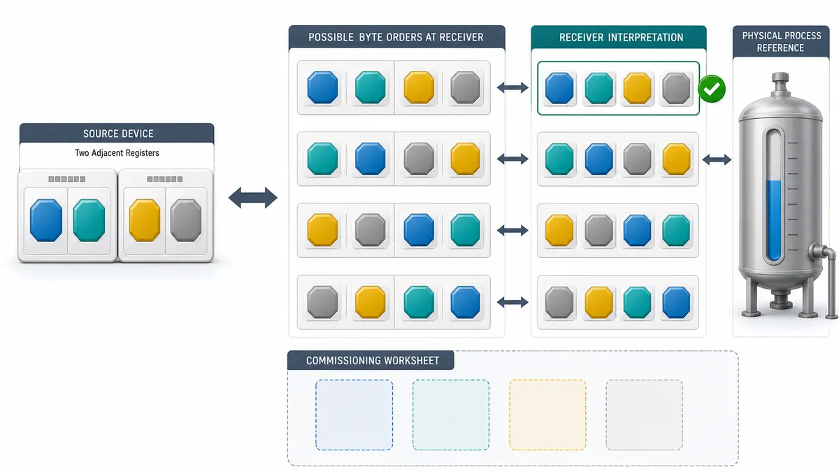
32-Bit Integer Encoding:
Register N:   High word (bits 31-16)
Register N+1: Low word (bits 15-0)
32-Bit Float (IEEE 754) Encoding:
Register N:   Bits 31-16 (sign, exponent, mantissa high)
Register N+1: Bits 15-0 (mantissa low)
Byte Order Variations: Different manufacturers implement different byte ordering:
- Big-endian: High byte first (Modbus standard)
- Little-endian: Low byte first (less common)
- Byte-swapped: Register order reversed
- Word-swapped: Byte pairs swapped
Example 32-bit Value 0x12345678:
| Format | Register N | Register N+1 |
|---|---|---|
| Big-endian | 0x1234 | 0x5678 |
| Little-endian | 0x7856 | 0x3412 |
| Byte-swapped | 0x5678 | 0x1234 |
| Word-swapped | 0x3412 | 0x7856 |
Always verify device documentation for multi-register data ordering to ensure correct value interpretation.
Chapter 7: Error Handling and Exception Responses
Understanding Modbus Exception Codes
Exception Response Format: When slaves detect request errors, they send exception responses with modified function code and error code:
[Slave ID] [Function Code + 0x80] [Exception Code] [CRC Lo] [CRC Hi]
Example Exception Response:
Request:  0x01 0x03 0xFF 0xFF 0x00 0x01 [CRC]  // Invalid address
Response: 0x01 0x83 0x02 [CRC]
          (Function 0x83 = 0x03 + 0x80, Exception Code 0x02)
Modbus Exception Codes Reference
| Code | Name | Description | Common Causes |
|---|---|---|---|
| 01 | Illegal Function | Unsupported function code | Wrong function for device type |
| 02 | Illegal Data Address | Invalid register address | Address out of range, non-existent |
| 03 | Illegal Data Value | Invalid data value | Value exceeds limits, wrong format |
| 04 | Slave Device Failure | Device malfunction | Hardware error, internal failure |
| 05 | Acknowledge | Long operation in progress | Command accepted, processing |
| 06 | Slave Device Busy | Device busy with operation | Retry request after delay |
| 07 | Memory Parity Error | Memory check failed | RAM error, corrupted data |
| 08 | Gateway Problem | Gateway configuration issue | Gateway path unavailable |
Handling Exception Responses: Master applications must detect exception responses by checking if function code high bit is set (≥0x80) and implement appropriate error handling based on exception code received.
CRC Error Detection
CRC Calculation Importance: Modbus RTU appends a 16-bit CRC to detect corrupted frames. A valid CRC means the received bits satisfy the check; it does not authenticate the sender, prevent replay, or prove that the register map and data interpretation are correct.
CRC Error Handling:
- Receivers silently discard frames with invalid CRC
- No exception response generated for CRC errors
- Master timeout mechanism detects missing response
- Retransmission required for frames rejected due to CRC errors
Common CRC Error Causes:
- Electrical noise on communication lines
- Poor cable quality or damaged cables
- Missing or incorrect termination resistors
- Ground potential differences
- Excessive cable length or too many nodes
- Improper wiring polarity
Timeout Handling Strategies
Master Timeout Configuration: Masters must implement timeout periods to detect:
- Non-responsive slaves (device failure or wrong address)
- CRC-rejected frames (transmission errors)
- Slave processing delays (busy device)
Timeout commissioning record:
| Input | Record |
|---|---|
| Request/response frame lengths and baud rate | Wire time for the largest required transaction |
| Slowest device or gateway operation | Measured processing and turnaround distribution |
| Poll schedule and number of retries | Worst-case cycle time and stale-data interval |
| Process requirement | Maximum acceptable data age and recovery time |
| Failure test | Disconnected, CRC-invalid, busy, exception, and delayed response behavior |
Timeout Recovery Actions:
- Log timeout event with timestamp and details
- Increment error counter for slave device
- Retry only according to the documented device and process policy
- Mark device as offline after repeated failures
- Implement exponential backoff for persistent failures
- Alert operators to communication problems
Chapter 8: PLC Implementation Examples
Siemens S7 Modbus RTU Configuration
Hardware Requirements:
- Siemens S7-1200/1500 PLC
- CM 1241 RS-485 communication module
- TIA Portal V13 or later programming software
Configuration Steps:
Step 1: Hardware Configuration
- Insert CM 1241 module in TIA Portal project
- Assign module to appropriate hardware slot
- Configure module properties:
- Baud rate: 19200
- Parity: Even
- Stop bits: 1
- Flow control: None
Step 2: Add Modbus Master Library
- Download Modbus library from Siemens support
- Import library into TIA Portal project
- Add library to project tree
Step 3: Create Modbus Connection
// Modbus Master Configuration
MB_MASTER(
    REQ := Start_Communication,
    MB_MODE := 0,  // RTU mode
    TIMEOUT := T#1s,
    CONNECT := HW_ID,
    DISCONNECT := FALSE,
    DONE => Communication_Done,
    BUSY => Communication_Busy,
    ERROR => Communication_Error,
    STATUS => Status_Word
);
Step 4: Read Holding Registers
// Read 10 Holding Registers
MB_Client_Read(
    REQ := Trigger_Read,
    MB_MODE := 0,  // Modbus RTU
    TIMEOUT := T#1s,
    MB_UNIT_ID := 1,  // Slave address
    CONNECT := HW_ID,
    MB_ADDR := 100,  // Starting register
    MB_LEN := 10,  // Quantity
    MB_DATA_PTR := ADR(Data_Array),
    DONE => Read_Done,
    BUSY => Read_Busy,
    ERROR => Read_Error
);
Step 5: Write Multiple Registers
// Write 5 Registers
MB_Client_Write(
    REQ := Trigger_Write,
    MB_MODE := 0,
    TIMEOUT := T#1s,
    MB_UNIT_ID := 1,
    CONNECT := HW_ID,
    MB_ADDR := 200,
    MB_LEN := 5,
    MB_DATA_PTR := ADR(Write_Array),
    DONE => Write_Done,
    BUSY => Write_Busy,
    ERROR => Write_Error
);
Allen-Bradley CompactLogix/ControlLogix Setup
Hardware Requirements:
- CompactLogix or ControlLogix PLC
- 1769-ASCII or 1756-SERIAL communication module
- Studio 5000 Logix Designer programming software
Configuration Steps:
Step 1: Module Configuration
- Add ASCII/Serial module to I/O configuration
- Configure module in Controller Properties:
- Protocol: User (for Modbus RTU)
- Baud Rate: 19200
- Data Bits: 8
- Parity: Even
- Stop Bits: 1
Step 2: Install Modbus Master Add-On Download and install ProSoft Modbus RTU Master Add-On Instruction (AOI) or similar library.
Step 3: Configure Modbus Master AOI
// Modbus Master Instance
MBM_Instance(
    Enable := TRUE,
    SerialPort := Local:2:I,  // ASCII module
    BaudRate := 19200,
    Parity := 2,  // Even
    Config := Config_Tag,
    Status := Status_Tag
);
Step 4: Read Holding Registers
// Read Function Code 03
Modbus_Read(
    Enable := TRUE,
    MasterRef := MBM_Instance,
    SlaveAddress := 1,
    Function := 3,  // Read Holding Registers
    StartAddress := 100,
    Quantity := 10,
    DataArray := HoldingRegs[0],
    Done := Read_Complete,
    Error := Read_Error,
    ErrorCode := Read_ErrorCode
);
Step 5: Write Registers
// Write Function Code 16
Modbus_Write(
    Enable := Write_Trigger,
    MasterRef := MBM_Instance,
    SlaveAddress := 1,
    Function := 16,  // Write Multiple Registers
    StartAddress := 200,
    Quantity := 5,
    DataArray := WriteData[0],
    Done := Write_Complete,
    Error := Write_Error
);
Generic PLC Implementation Guidelines
Universal Implementation Checklist:
1. Communication Module Setup
- Configure baud rate (19200 recommended for reliability)
- Set parity to Even (most common) or None
- Configure 8 data bits, 1 stop bit
- Enable RS-485 mode if selectable
2. Message Formatting
- Create data structures for requests and responses
- Implement CRC-16 calculation function
- Build message assembly routines
- Implement message parsing functions
3. Timing Management
- Implement 3.5 character time delays
- Configure appropriate timeout values
- Manage polling intervals between devices
- Prevent request queue buildup
4. Error Handling
- Detect and log timeout errors
- Parse exception responses
- Implement retry logic with backoff
- Track communication statistics
5. Testing Procedures
- Test single device communication first
- Verify CRC calculations match
- Test all required function codes
- Validate error handling behavior
- Load test with multiple devices
Chapter 9: Troubleshooting Modbus RTU Networks

Common Communication Problems
Problem: No Communication
Symptoms:
- Master shows timeout errors
- Slave device not responding
- All communication attempts fail
Diagnostic Steps:
-
Verify Physical Connections:
- Check cable continuity with multimeter
- Verify A and B wire connections (not reversed)
- Confirm power to all devices
- Inspect connectors for damage or corrosion
-
Check Communication Settings:
- Verify matching baud rate on all devices
- Confirm parity settings match
- Validate slave address configuration
- Ensure proper mode (RTU vs ASCII)
-
Test with Known-Good Device:
- Replace suspected faulty device temporarily
- Swap cables to isolate cable problems
- Test communication module in different slot
Solutions:
- Correct mismatched communication parameters
- Replace faulty cables or connectors
- Repair or replace failed communication module
- Verify device configuration matches documentation
Problem: Intermittent Communication
Symptoms:
- Random timeout errors
- Occasional CRC failures
- Unreliable data values
- Communication works then fails
Diagnostic Steps:
-
Check Signal Quality:
- Measure voltage levels on A and B lines
- Look for noise spikes with oscilloscope
- Verify ground connections are solid
- Check for loose connections
-
Verify Network Configuration:
- Confirm termination resistors installed correctly
- Check for cable stubs or improper topology
- Measure total cable length
- Count number of connected nodes
-
Identify Interference Sources:
- Locate nearby VFDs or switching power supplies
- Check for parallel runs with power cables
- Identify welders or other noise sources
- Test shielding effectiveness
Solutions:
- Install proper 120Ω termination at both cable ends
- Route cables away from noise sources
- Use shielded twisted-pair cable properly grounded
- Add isolation between devices if needed
- Reduce baud rate for marginal signal quality
Problem: Wrong or Corrupted Data
Symptoms:
- Values received don't match expected
- Data changes unexpectedly
- Scaling appears incorrect
- Sign errors (negative vs positive)
Diagnostic Steps:
-
Verify Address Mapping:
- Confirm protocol addresses match documentation
- Check for 0-based vs 1-based confusion
- Validate register address ranges
- Review device address map documentation
-
Check Data Type Handling:
- Verify byte order (big/little endian)
- Confirm multi-register data ordering
- Check signed vs unsigned interpretation
- Validate floating-point format
-
Examine Scaling Factors:
- Review engineering unit conversions
- Check decimal point positions
- Verify scaling multipliers and offsets
- Confirm range limits
Solutions:
- Correct address offset errors (add or subtract 1)
- Implement proper byte swapping for 32-bit values
- Apply correct scaling formulas
- Use proper data type declarations
- Test with known values to verify interpretation
Diagnostic Tools and Techniques
Software Tools:
Modbus Poll (Master Simulator):
- Simulate master and test slave devices
- Monitor communication traffic
- Test different function codes
- Validate device responses
- Available: www.modbustools.com
Modbus Slave (Slave Simulator):
- Simulate slave devices for master testing
- Create custom register maps
- Test master implementations
- Generate test scenarios
Wireshark with Modbus Dissector:
- Capture serial communication (requires USB-serial adapter)
- Decode Modbus RTU frames
- Analyze timing and message flow
- Identify protocol violations
Terminal Programs:
- RealTerm, Termite, or similar
- View raw serial data in hex
- Send test messages manually
- Verify basic communication
Hardware Tools:
Multimeter:
- Verify power supply voltages
- Check continuity of cables
- Measure resistance of termination
- Test for short circuits
Oscilloscope:
- Display differential signals
- Measure timing intervals
- Identify noise and reflections
- Verify signal amplitude
RS-485 Tester:
- Dedicated test device for RS-485
- Tests cable quality and termination
- Measures signal quality metrics
- Generates test patterns
Cable Tester:
- Verify twisted-pair continuity
- Check for shorts and opens
- Test cable shield integrity
- Measure cable length
Troubleshooting Methodology
Step 1: Isolate the Problem
- Test communication with one slave device only
- Disconnect other devices temporarily
- Use short cable run for initial testing
- Eliminate variables systematically
Step 2: Verify Basics
- Confirm power to all devices
- Check all cable connections
- Verify communication parameters match
- Test with known-good hardware
Step 3: Capture Data
- Log error messages and conditions
- Record communication statistics
- Capture problematic message sequences
- Document environmental conditions
Step 4: Analyze Systematically
- Review captured data for patterns
- Check timing relationships
- Examine error frequency and distribution
- Correlate with physical conditions
Step 5: Test Solutions
- Change one variable at a time
- Verify improvement after each change
- Document changes and results
- Retest under normal operating conditions
Chapter 10: Modbus RTU Best Practices
Polling Strategy Optimization
Efficient Polling Techniques:
Priority-Based Polling:
- Read critical data more frequently
- Poll less important data at slower rates
- Adjust polling based on process requirements
- Implement event-triggered reads for alarms
Example Polling Schedule:
Fast Loop (100ms):  Critical process values, alarms
Medium Loop (1s):   Setpoints, status information
Slow Loop (10s):    Configuration data, diagnostics
On-Demand:          One-time reads, parameter changes
Minimize Network Traffic:
- Use Write Multiple Registers instead of multiple single writes
- Read consecutive registers in single transaction
- Avoid unnecessary reads of static data
- Implement change-of-state detection where possible
Balance Load Across Slaves:
- Distribute polling evenly over time
- Avoid burst patterns that congest network
- Consider slave processing capabilities
- Monitor network utilization
Error Recovery Strategies
Retry Logic:
Retry_Attempt = 0
Max_Retries = 3
Retry_Delay = 100ms

On Communication_Error:
    If Retry_Attempt < Max_Retries:
        Wait(Retry_Delay)
        Retry_Attempt++
        Resend_Request()
    Else:
        Mark_Device_Offline()
        Alert_Operator()
        Reset_Retry_Counter()
Exponential Backoff: For persistent communication problems, increase delay between retries exponentially to reduce network congestion from failing devices.
Graceful Degradation:
- Continue operating with partial data when possible
- Use last known good values temporarily
- Alert operators to reduced capability
- Log all degraded operation periods
Communication Health Monitoring:
For Each Slave:
    Success_Count = 0
    Error_Count = 0
    Success_Rate = Success_Count / (Success_Count + Error_Count)

    If Success_Rate < 90%:
        Generate_Warning()
    If Success_Rate < 50%:
        Generate_Alarm()
Security Considerations
Physical Security:
- Locate serial networks in secured areas
- Protect cable runs from tampering
- Lock communication module access
- Control physical access to network equipment
Network Isolation:
- Keep Modbus RTU networks separate from IT networks
- Use protocol converters as security boundary
- Implement firewalls between network segments
- Monitor for unauthorized access attempts
Authentication Limitations: Standard Modbus RTU provides no authentication or encryption. For sensitive applications:
- Use Modbus security extensions where available
- Implement application-layer security
- Consider Modbus TCP with VPN for secure remote access
- Log all configuration changes
Access Control:
- Limit write access to authorized devices
- Implement read-only connections where possible
- Use separate master for configuration vs monitoring
- Audit all write operations
Documentation Requirements
Network Documentation:
- Complete network topology diagram
- Cable routing and length information
- Termination locations and values
- Node address assignments
Device Documentation:
- Device specifications and manuals
- Register address maps for each device
- Communication parameter settings
- Firmware versions and update history
Application Documentation:
- Master polling configuration
- Data point assignments
- Alarm and event definitions
- Error handling logic
Maintenance Records:
- Communication error logs
- Network modifications history
- Troubleshooting actions and results
- Performance measurements over time
Chapter 11: Modbus Protocol Comparison
Modbus RTU vs Modbus TCP/IP
| Aspect | Modbus RTU | Modbus TCP/IP |
|---|---|---|
| Physical Layer | RS-232/485 serial | Ethernet (10/100/1000) |
| Topology | Bus (multi-drop) | Star/switched network |
| Addressing / scale | Addresses 1–247; electrical segment and poll-cycle limits are separate | Endpoint, Unit ID, connection, switch, and product limits apply |
| Distance | Serial physical-layer and installation dependent | Ethernet medium and topology dependent |
| Speed | Device and serial-line dependent | Network and device dependent |
| Protocol Overhead | Minimal | TCP/IP headers |
| Error Checking | CRC-16 | TCP checksums |
| Message ID | Slave address (1 byte) | Transaction ID (2 bytes) + Unit ID |
| Implementation Cost | Low | Medium |
| Complexity | Simple | More complex |
| Best Application | Serial legacy devices | Modern networked systems |
When to Choose Modbus RTU:
- Long-distance serial communication needed
- Existing RS-485 infrastructure
- Simple point-to-point or multi-drop networks
- Cost-sensitive applications
- Legacy device integration
When to Choose Modbus TCP:
- Ethernet infrastructure available
- High-speed data transfer required
- Integration with IT systems needed
- Switched Ethernet topology or independent connections fit the scale and availability design
- Remote access through WAN/Internet
Migration from Modbus RTU to TCP
Protocol Gateways: Convert between Modbus RTU and Modbus TCP:
- Maintain existing serial devices
- Enable Ethernet connectivity
- Bridge legacy and modern systems
- Centralize network management
Direct Replacement: Replace serial devices with Ethernet-enabled equivalents:
- Upgrade network infrastructure to Ethernet
- Reconfigure master for TCP communication
- Update address assignments (Unit IDs)
- Test thoroughly before production deployment
Hybrid Approach: Maintain both networks during transition:
- Deploy new devices on Ethernet
- Keep critical legacy devices on serial
- Gradually phase out serial network
- Minimize disruption to operations
Frequently Asked Questions About Modbus RTU
What does RTU stand for in Modbus RTU? RTU stands for Remote Terminal Unit. Modbus RTU uses binary encoding and is designed for serial communication with remote field devices, offering compact message size and efficient communication compared to Modbus ASCII.
What is the maximum number of devices on Modbus RTU network? The serial protocol provides slave addresses 1–247 and reserves address 0 for broadcast. That does not mean 247 devices can share one electrical segment. Transceiver unit load, biasing, termination, cable, topology, repeaters, device limits, and required poll time determine the practical node count.
What baud rate should I use for Modbus RTU? Use a rate supported by every device and validate it on the installed cable, topology, length, and noise environment. Higher rates shorten wire time but reduce timing and signal-integrity margin. Record framing, parity, stop bits, and the final tested rate in the network schedule.
Can Modbus RTU work without parity? Yes, Modbus RTU can operate without parity by using 8 data bits, no parity, and 2 stop bits (8N2) or with Even parity using 8 data bits, even parity, 1 stop bit (8E1). All devices must use identical settings. Even parity is more common.
What is the maximum cable length for Modbus RTU? Modbus does not define one maximum cable length. For an EIA/TIA-485 implementation, allowable length depends on data rate, cable impedance and capacitance, conductor size, topology, stubs, unit load, termination, biasing, isolation, common-mode voltage, and EMC conditions. Use the transceiver and device manuals, then prove margin on the installed network.
How do I calculate the correct timeout value? Start with request wire time + the slowest documented or measured device processing time + response wire time + gateway/turnaround delay. Add margin based on the measured distribution, then test delayed, missing, busy, exception, and CRC-invalid responses. Verify that retries cannot make the overall data age or control response exceed the process requirement.
What causes CRC errors in Modbus RTU communication? CRC errors result from electrical noise, poor cable quality, missing termination resistors, excessive cable length, too many nodes, improper wiring, ground loops, or damaged cables. Use shielded twisted-pair cable, proper termination, and good grounding practices.
Why is my Modbus address different in the software than in the documentation? Modbus documentation often uses 1-based addressing (40001 for first holding register) while protocol messages use 0-based addressing (0x0000 for first register). Always clarify which addressing scheme your software and devices use to avoid communication failures.
Can multiple masters control the same Modbus RTU network? No, standard Modbus RTU allows only one master at a time. Multiple masters cause message collisions and communication failures. Use master arbitration schemes, master/backup configurations, or Modbus TCP for multi-master requirements.
What is the difference between holding registers and input registers? Holding registers (4x addresses, function codes 03/06/16) are read/write registers typically used for setpoints, control parameters, and bidirectional data. Input registers (3x addresses, function code 04) are read-only registers typically used for sensor measurements and process variables.
How do I read 32-bit values from Modbus devices? Read two consecutive 16-bit registers and combine them according to device byte order. Check device documentation for byte ordering (big-endian, little-endian, byte-swapped, or word-swapped) to correctly interpret 32-bit integers, floating-point values, and long integers.
What does exception code 02 (Illegal Data Address) mean? Exception code 02 indicates the requested address doesn't exist in the slave device, is outside the allowed range, or the device doesn't implement that register. Verify address mapping documentation and check for 0-based vs 1-based addressing confusion.
Conclusion: Master Modbus RTU for Industrial Communication Success
Understanding frame structure, function codes, addressing, RS-485 wiring and troubleshooting helps you implement and maintain Modbus RTU networks without relying on trial and error.
For every installation, retain the exact device register maps, serial settings, wiring drawing and a captured known-good request/response pair. Those artifacts are more useful than a general claim of universal compatibility.
Future success in automation engineering requires both understanding established protocols like Modbus RTU and keeping current with emerging technologies. This dual expertise enables you to maintain existing systems while designing next-generation industrial communication networks that meet Industry 4.0 requirements.
Related PLC Communication Resources
Expand your industrial communication knowledge beyond Modbus RTU:
- PLC Communication Protocols Guide - Compare all major industrial protocols
- Structured Text Programming Guide - Advanced PLC programming for communication handling
- HMI Programming Tutorial - Create operator interfaces that communicate via Modbus
- Siemens PLC Programming Tutorial - Implement Modbus on Siemens platforms
Accelerate Your PLC Programming Career
Ready to become a PLC programming expert with advanced communication skills? Our comprehensive Master PLC Programming Guide covers everything from basic concepts to advanced industrial protocols including Modbus RTU, EtherNet/IP, and Profinet. Download your complete resource today and master the skills that drive modern industrial automation.
Continue developing your Modbus RTU expertise through hands-on practice with different devices, studying vendor implementation guides, and staying current with emerging industrial communication technologies that complement and extend traditional serial protocols in 2026 and beyond.


