RTD and PT100 Guide: 2-, 3- & 4-Wire Measurement
Understand resistance temperature detectors and PT100 sensors, choose 2-, 3- or 4-wire measurement, estimate lead error, configure a transmitter and troubleshoot a loop.
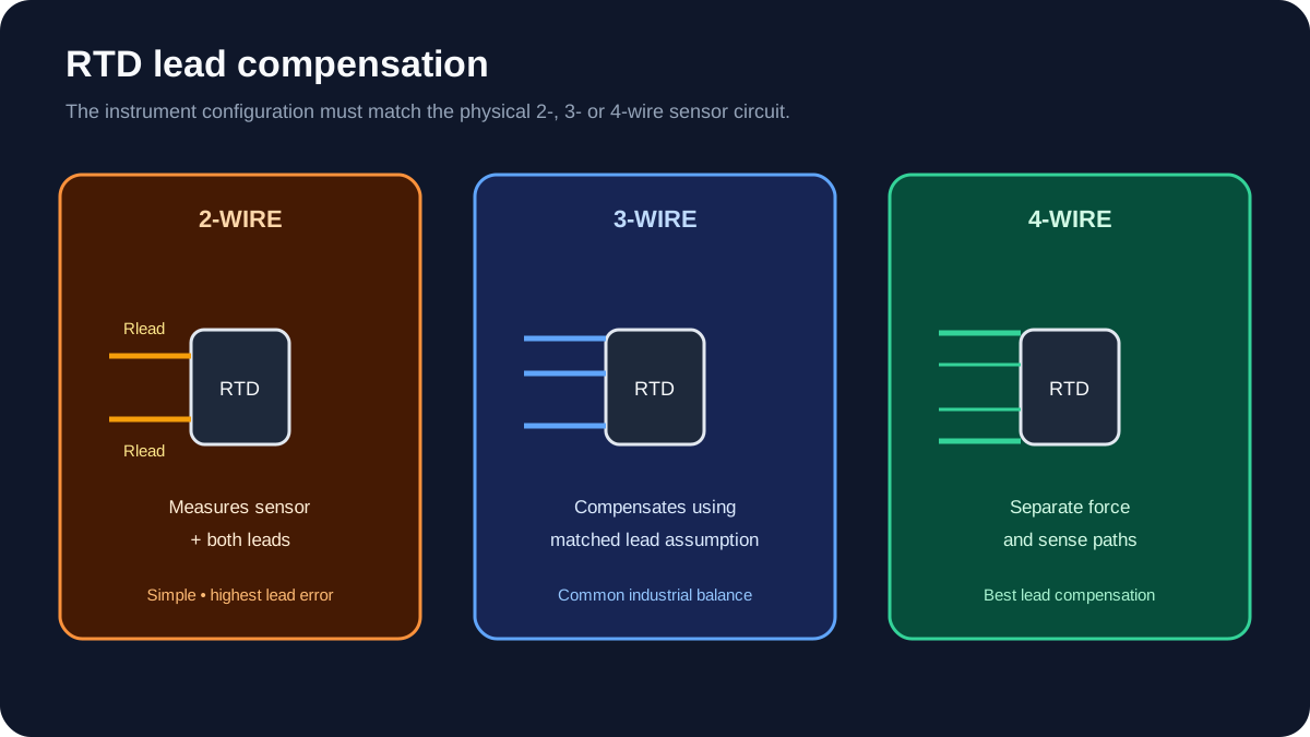
A resistance temperature detector (RTD) measures temperature through a predictable change in electrical resistance. A common industrial PT100 is nominally 100 Ω at 0 °C. Two-wire measurement includes both lead resistances; three-wire measurement compensates when matched leads and the input circuit support it; four-wire measurement measures resistance with the best lead compensation.
Download the RTD/PT100 loop-check worksheet (CSV)
RTD selection summary
| Decision | Typical options | Check |
|---|---|---|
| Element | Pt100, Pt1000, other material/nominal resistance | Input compatibility and required range |
| Construction | Thin film, wire wound, industrial probe | Accuracy, stability, vibration and cost |
| Connection | 2-, 3- or 4-wire | Lead error and instrument support |
| Mechanical | Probe, insert, spring-loaded assembly, surface sensor | Immersion, response and maintainability |
| Process interface | Direct insertion or thermowell | Pressure, velocity, corrosion and removal |
| Output | Direct RTD input or head/rail transmitter | Distance, noise, diagnostics and standardisation |
| Tolerance | Applicable IEC/manufacturer class | Total loop accuracy, not label alone |
How a PT100 changes with temperature
Platinum RTDs have a positive temperature coefficient: resistance rises as temperature rises. For the common industrial 0.00385 Ω/Ω/°C characteristic, a PT100 changes by roughly 0.385 Ω per °C near 0 °C.
A useful local sense check near 0 °C is:
Approximate temperature ≈ (measured resistance − 100 Ω) / 0.385 Ω/°C
This linear approximation is not the full conversion over a wide range. Accurate conversion uses the specified RTD curve and coefficients, commonly expressed through the Callendar–Van Dusen relationship. Configure the exact sensor type in the transmitter, PLC card or calibrator.
2-wire RTD
The instrument sees:
Rmeasured = Rsensor + Rlead1 + Rlead2
Worked lead-error example
If each lead contributes 0.8 Ω:
Added resistance = 0.8 + 0.8 = 1.6 Ω
Approximate error near 0 °C = 1.6 / 0.385 ≈ 4.2 °C
That is a large error for many process loops. Two-wire can still be acceptable for short runs or low-accuracy duties, especially with higher-resistance elements, but the error must be calculated rather than ignored.
3-wire RTD
A three-wire input uses an additional lead to estimate and compensate lead resistance. The common assumption is that the relevant leads have equal resistance.
Use:
- the same conductor size and material;
- the same route and ambient exposure;
- terminals and barriers that do not create a large imbalance;
- the exact instrument terminal diagram.
Three-wire is common in industrial process measurement because it balances accuracy and cable count. Compensation is imperfect when lead resistances differ.
Live mini-lab
Try it: press START, then STOP
A stop-dominant seal-in rung: START latches the motor output through its own contact, and STOP breaks the circuit.
Watch the output lamp: it stays on after START until you press STOP.
Free · no signup to try · runs in your browserOpens plcsimulationsoftware.com — same team
4-wire RTD
Four-wire measurement separates excitation current from voltage sensing. Because very little current flows in the sense leads, their voltage drop can be excluded from the resistance result.
Four-wire is preferred for high-accuracy or calibration work and long leads when supported. Fluke's resistance-measurement guide explains how the separate force/sense connection compensates test-lead resistance.
Direct PLC input vs temperature transmitter
Direct RTD input
Advantages:
- fewer field devices;
- direct resistance measurement;
- potentially lower hardware cost for short local runs.
Checks:
- supported RTD type and curve;
- 2/3/4-wire terminal arrangement;
- channel isolation and common-mode limits;
- lead resistance limit;
- open/short diagnostic behaviour;
- conversion/filtering time.
RTD transmitter
A head- or rail-mounted transmitter converts the RTD measurement to 4–20 mA or a digital protocol.
Advantages:
- robust long-distance current loop;
- sensor-break diagnostics;
- local linearisation;
- galvanic isolation where provided;
- easier standardisation of PLC analog cards.
Checks:
- configured sensor and wire count;
- range and units;
- upscale/downscale failure behaviour;
- transmitter accuracy and ambient effects;
- loop power and load;
- HART or other digital configuration control.
Wiring a 3-wire PT100
Wire colours are not universal enough to replace documentation. Identify which two leads connect to the same end of the element using the probe data sheet or a controlled resistance test.
General workflow:
- Isolate the loop and follow the site's process/electrical safety procedure.
- Identify the three leads and element arrangement.
- Connect the paired leads to the two same-side instrument terminals.
- Connect the remaining lead to the opposite-side terminal.
- Configure sensor type, coefficient/curve and 3-wire mode.
- Verify ambient reading for plausibility.
- Perform a documented simulation or temperature test.
If swapping the two same-side leads changes the result materially, investigate terminal resistance, barriers, cable damage or input configuration.
Scaling a 4–20 mA temperature transmitter
For a transmitter ranged −50 to 150 °C:
Span = 150 − (−50) = 200 °C
Temperature = −50 + ((mA − 4) / 16) × 200
At 12 mA:
Temperature = −50 + (8 / 16 × 200)
            = 50 °C
Add diagnostics outside the normal signal band according to the transmitter, input card and site standard. Do not clamp every under-range value to −50 °C; that hides a possible sensor/loop fault.
Installation errors that dominate accuracy
Insufficient immersion
Stem conduction can pull the sensor toward ambient temperature. Follow the probe/thermowell manufacturer's immersion guidance and compare insertion length with process geometry.
Poor thermowell contact
Incorrect insert length, missing spring loading or debris can create slow response and bias.
Wrong transmitter configuration
A Pt100 configured as Pt1000—or the wrong coefficient—can produce a plausible but incorrect value.
Self-heating
Measurement current heats the RTD element. Input/transmitter design and sensor dissipation determine the effect.
Lead imbalance
Three-wire compensation assumes matched resistance. Mixed conductor sizes, wet terminals or damaged joints create error.
Ground loops and noise
Shielding, isolation, grounded versus ungrounded element construction and cable routing must match the system design.
Calibration and loop testing
Fluke's RTD calibration procedure distinguishes testing the sensor from testing the connected electronics. That distinction should appear in the test record.
Sensor-only test
- isolate the sensor from the process as required;
- compare it in a stable temperature source with a traceable reference;
- measure resistance with a suitable instrument;
- compare measured resistance to the applicable sensor table/curve.
Transmitter/input test
- disconnect or isolate the sensor under procedure;
- simulate the configured RTD type and wire arrangement;
- test at minimum 0%, 50% and 100% plus a fault condition;
- verify indicated temperature, output current and system alarm;
- record as-found and as-left results.
Full-loop check
A full-loop test confirms sensor/process response, transmitter, wiring, PLC scaling, HMI display, alarms and historian path. It does not replace a sensor calibration when sensor accuracy must be proven.
Troubleshooting table
| Symptom | Checks |
|---|---|
| Reading high by a stable amount | 2-wire lead resistance, 3-wire imbalance, terminal resistance |
| Reading extremely high/open | broken lead, loose terminal, wrong wire arrangement |
| Reading near zero/very low | shorted leads, moisture, wrong sensor type |
| Value jumps with vibration | intermittent lead or thermowell/probe connection |
| Slow response | immersion, thermowell fit, process contact, filtering |
| PLC and calibrator disagree | curve/type, wire mode, scaling, input range |
| Several channels shift together | common reference, module, cabinet temperature or configuration |
Primary references
- Fluke, Resistance thermometer basics and RTD calibration.
- Fluke, Calibrating and testing RTD sensors.
- Fluke, 2-wire and 4-wire resistance measurement methods.
- Use the exact sensor, transmitter and input-module manuals for curve, terminal and diagnostic configuration.
Related guides
Now run it · free · no signup
Wire a 24 VDC sensor to a PLC input
Connect sensor power and signal, present a target and prove the live PLC input changes. Free browser lab — no signup required to finish it.
Ownership disclosure: PLC Programming IO and PLC Simulation Software are operated by the same publisher.


