PROFIBUS Cable Guide: Length, Termination & Faults
Design and troubleshoot PROFIBUS DP RS-485 cable using the correct segment length, two powered terminations, shielding, connector assembly and commissioning tests.
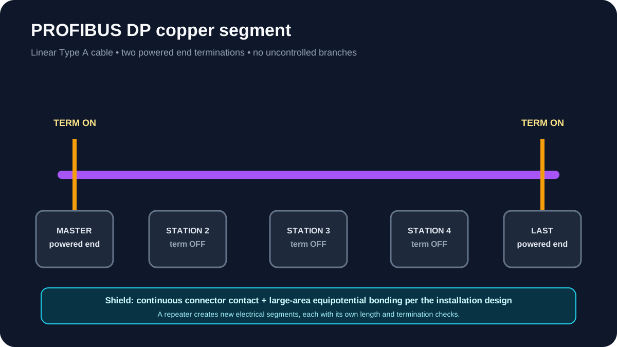
A reliable PROFIBUS DP copper segment uses approved Type A cable, a linear RS-485 topology, termination at exactly the two segment ends, effective shield bonding and length within the limit for its data rate. Most intermittent faults come from the physical layer: extra or unpowered terminators, long branches, damaged connectors, poor shielding or a segment that became too long after changes.
Download the PROFIBUS commissioning worksheet (CSV)
PROFIBUS DP length by data rate
For RS-485 with Type A cable, PI's system description gives these maximum transmission ranges per segment:
| Data rate | Maximum segment length |
|---|---|
| 9.6, 19.2, 45.45 or 93.75 kbit/s | 1,200 m |
| 187.5 kbit/s | 1,000 m |
| 500 kbit/s | 400 m |
| 1.5 Mbit/s | 200 m |
| 3, 6 or 12 Mbit/s | 100 m |
These are design maxima for the specified physical layer, not permission to ignore connector count, cable condition, EMC, topology or manufacturer rules. A repeater divides the network into separate electrical segments; count and terminate each segment separately.
Source: PROFIBUS & PROFINET International, PROFIBUS System Description.
Worked segment calculation
Assume a 1.5 Mbit/s PROFIBUS DP network follows a packaging line:
| Cable section | Route length |
|---|---|
| PLC cabinet to drive cabinet | 42 m |
| Drive cabinet to remote I/O | 38 m |
| Remote I/O to operator station | 31 m |
| Service and cabinet routing allowance | 14 m |
| Estimated electrical segment | 125 m |
The 1.5 Mbit/s maximum is 200 m, so the estimated segment is inside the protocol limit. That does not finish the design. The engineer should still confirm that there are no unrecorded branches, use approved connectors and Type A cable, put termination at the PLC-cabinet end and operator-station end, and confirm that both terminations remain powered.
The remaining 75 m is design margin, not spare cable that can automatically be consumed. A later 60 m machine extension could still create poor routing, an unintended branch or a new end station whose power is routinely isolated. If the extension is required, redraw the topology and decide whether a repeater should create a separately calculated segment.
At commissioning, replace estimated lengths with installed route data, record the two termination points, and save a diagnostic baseline. That turns “it is under 200 m” into a testable physical-layer record.
Cable and connector essentials
Typical PROFIBUS DP Type A copper cable is a shielded twisted pair with defined impedance and capacitance characteristics. Use cable and connectors intended for the protocol and environment, including:
- fixed, flexible, trailing or torsion application;
- indoor/outdoor sheath;
- chemical and oil exposure;
- temperature and flame requirements;
- intrinsically safe RS-485-IS design where applicable;
- Sub-D, M12 or direct termination supported by the device.
Do not substitute generic purple cable or ordinary twisted pair based on colour and conductor count.
Live mini-lab
Try it: press START, then STOP
A stop-dominant seal-in rung: START latches the motor output through its own contact, and STOP breaks the circuit.
Watch the output lamp: it stays on after START until you press STOP.
Free to start · runs in your browserOpens plcsimulationsoftware.com — same team
Termination: exactly two segment ends
PI's installation guidance states that RS-485 segments are terminated at both ends and nowhere else. Extra terminations load and distort the signal; a missing termination allows reflections.
Many 9-pin connectors contain a switchable active termination. Switching it on can also isolate the outgoing cable. Therefore:
- use the marked incoming port at an end connector;
- leave the outgoing port empty at the segment end;
- keep both end terminators powered during network operation;
- set every intermediate connector termination to OFF;
- after replacing or moving a station, recount the physical segment ends.
An end device powered off may remove power from its active termination and destabilise the whole segment. If end stations are routinely isolated, use an approved termination arrangement that remains powered as the design requires.
PI's termination guide explains both the two-end rule and the connector isolation trap.
Shielding and equipotential bonding
The cable shield is part of the transmission system. PI's installation guidance calls for effective, low-impedance, large-area bonding rather than a long pigtail.
Key practices:
- terminate the cable shield correctly in each connector;
- bond the shield/equipment to the plant's equipotential bonding system as designed;
- use a large-area shield clamp at cabinet entry where required;
- do not use a painted rail or surface as the electrical bond;
- protect the stripped shield area from mechanical damage;
- do not use the shield clamp as strain relief unless it is designed for that purpose;
- address potential differences between buildings/areas through the electrical/EMC design.
See PI's shielding and equipotential-bonding guidance.
Topology rules
Classic PROFIBUS DP RS-485 uses a bus/line topology. Avoid uncontrolled branches and star wiring. A service connector or spur adds electrical length and can create reflections, particularly at higher data rates.
Where a star, long branch, galvanic isolation or additional distance is required, use an approved repeater, hub or optical link and treat each output as its documented segment type.
Record:
- controller/master and every station address;
- cable route and measured/estimated length;
- connector type;
- segment and repeater boundary;
- termination location and power source;
- data rate;
- shield-bonding points;
- spare cores/cables and changes.
Addressing and physical faults are different
An address conflict is a configuration fault; it can look like a cable problem because stations disappear. Physical-layer faults can also appear device-specific because the waveform is worst at one location.
Use a disciplined order:
- Record the fault state before touching connectors.
- Check which stations fail and whether the pattern follows a segment.
- Verify termination and end-station power.
- Check new work, moved stations and recently opened connectors.
- Inspect address and data-rate settings.
- Examine repeater and diagnostic-device counters.
- Use a PROFIBUS analyser/oscilloscope method appropriate to the system.
- Change one condition at a time and preserve evidence.
Symptom-to-cause map
| Symptom | High-value first checks |
|---|---|
| Whole segment fails when one end device is off | active termination lost with station power |
| Network works at low rate but not high rate | length, branch, connector or cable-quality margin |
| Intermittent faults when drive runs | shield bonding, cable separation, equipotential bonding, connector assembly |
| Stations after one point disappear | open conductor/connector or repeater power |
| One device drops occasionally | local connector, address, shield contact, device power |
| Errors after cabinet work | termination switch, swapped A/B conductors, damaged shield, pinched cable |
| Many retries but no obvious station loss | marginal waveform, excess length, extra termination, EMC |
Connector inspection
With the segment placed in an approved safe state:
- verify A/B conductors use the correct terminals consistently;
- check no strand or shield touches a data conductor;
- keep unshielded core length to the connector's instructions;
- verify a large-area shield connection;
- check strain relief without crushing the cable;
- confirm IN/OUT orientation;
- record termination switch position;
- inspect bend radius and mechanical damage.
PI's cabling and assembly guideline provides illustrated assembly, routing and commissioning material.
Acceptance and commissioning
Design record
- data rate and required response time;
- segment length calculation;
- node count and repeater boundaries;
- cable/connector part numbers;
- routing and separation plan;
- earthing/equipotential-bonding design.
Installation checks
- cable route and length match the drawing;
- two terminations per electrical segment;
- end terminations remain powered;
- addresses are unique;
- shields and connectors are assembled correctly;
- repeater and device supplies are healthy.
Diagnostic baseline
- station list and firmware;
- retry/error counters;
- analyser result or waveform where required;
- fault log under stopped and running drives;
- photographs of each segment end;
- signed network drawing.
PROFIBUS PA is not the same physical layer
PROFIBUS PA commonly uses MBP physical-layer technology at 31.25 kbit/s, with power and communication on the bus and a trunk/spur architecture. Do not apply the DP RS-485 length table, connectors or termination circuit to a PA segment. Couplers, segment protectors, intrinsic-safety design and fieldbus power calculations require their own engineering.
Primary references
- PROFIBUS & PROFINET International, current installation-guide index.
- PI, PROFIBUS installation guidelines for design, cabling and commissioning.
- PI, PROFIBUS System Description.
Related guides
Now run it · free to start
Practise the PLC side of industrial networks
Compare EtherNet/IP, PROFINET, IO-Link and OPC UA by data flow and common commissioning failures, then practise the controller logic in your browser.
Ownership disclosure: PLC Programming IO and PLC Simulation Software are operated by the same publisher.


