Safe Torque Off (STO): VFD Safety, Wiring Concepts and Tests
Understand what Safe Torque Off does, when a motor can coast or a load can fall, how dual-channel STO fits a safety function, and how to validate and troubleshoot it without confusing torque prevention with isolation.
Review status: Vendor-neutral functional-safety boundaries reviewed against current ISO machinery-risk and safety-control-system catalog records, OSHA hazardous-energy requirements, and current Siemens and Rockwell Automation drive manuals; the exact drive safety manual, risk assessment, safety requirement specification, calculations, wiring, commissioning and validation remain application-specific
Direct answer
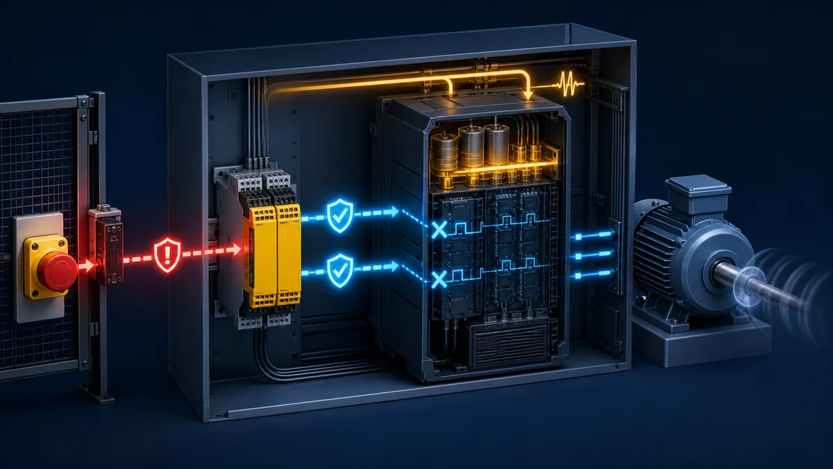
Safe Torque Off (STO) is a drive-integrated safety function that prevents the power stage from supplying torque-producing energy to a motor. When STO is demanded and the complete safety function operates correctly, the motor cannot generate driven torque or restart from the drive. A rotating load will normally coast unless another safe stop function decelerates it first. A suspended or unbalanced load may move under gravity unless a suitably designed brake function holds it.
STO is not an electrical isolator, a proof of zero speed, a mechanical brake, or a universal emergency-stop design. The drive's mains and DC bus can remain energized. The correct implementation starts with a machinery risk assessment and safety requirement specification, then uses the exact drive safety manual to design, calculate, commission and validate the input, logic and final-element chain.
The shortest useful mental model is: a safety device makes a demand; certified safety logic evaluates it; STO inhibits motor torque; machine mechanics determine how motion ends. Every part of that sentence needs evidence.
Safe Torque Off at a glance
| Question | Correct answer | Dangerous assumption to avoid | Evidence to retain |
|---|---|---|---|
| what does STO prevent? | torque-producing energy and unintended drive restart, within the certified function | “all electrical energy is gone” | drive safety manual, status and functional test |
| what happens to a rotating motor? | it normally coasts unless another function controls the stop | “STO is an instant stop” | worst-case stopping-time measurement |
| what happens to a vertical load? | gravity can move it unless a suitable brake/safety function controls it | “no motor torque means the load is held” | load analysis, brake design and tests |
| is the drive safe to touch? | not on the basis of STO; hazardous voltage may remain | “STO equals isolation” | site energy-control procedure and voltage verification |
| what selects STO? | the validated safety function defined by the risk assessment | any convenient standard PLC bit | safety requirement specification and architecture calculation |
| when can operation resume? | only after the demand clears and reset/restart conditions are satisfied | restoring a retained run command is acceptable | reset location, restart logic and negative tests |
What STO actually does inside a VFD
It inhibits the torque-producing path
A variable-frequency drive controls motor torque by switching power semiconductors. STO acts on the drive's certified gate-control or pulse-inhibit path so that the motor is no longer supplied with the switching pattern needed to generate torque. The precise internal design, claimed Performance Level (PL), Safety Integrity Level (SIL), proof-test interval and fault exclusions belong to the manufacturer's safety documentation—not to a generic diagram.
Current manufacturer documentation makes the boundary concrete. The Rockwell Automation PowerFlex 520-series manual describes the PowerFlex 525 function as disabling output IGBTs through the safety inputs. The Siemens SINAMICS S210 Safety Integrated manual states that no torque-producing energy is supplied, that a rotating motor coasts, and that there is no galvanic isolation between motor and drive. Those are useful principles, but neither manual can be used to wire a different drive family.
Power can remain present
STO commonly leaves the mains input, rectifier, DC-link capacitors and internal control circuits energized. This permits fast recovery and diagnostic access, but it also means covers, conductors and motor terminals cannot be treated as de-energized. A permanent-magnet motor that is turning may generate voltage. Stored electrical, pneumatic, hydraulic, gravitational and mechanical energy must be addressed separately.
For servicing covered by hazardous-energy rules, follow the site's isolation procedure. In the United States, OSHA 29 CFR 1910.147 requires an energy-control program for covered servicing and maintenance where unexpected energization, startup or energy release could cause injury. STO is a control-system safety function; it is not automatically an energy-isolating device.
STO status is not proof of standstill
A drive can report “STO active” while the shaft is still moving. That status proves only what the certified manual says it proves. If the application needs safe standstill monitoring, safely limited speed, safe direction, safe brake control or another motion function, specify and validate that function separately. Never synthesize a safety claim from ordinary speed feedback unless the complete architecture is suitable and calculated.
STO, normal stop, emergency stop and isolation compared
| Method or function | Main purpose | What happens to motion? | Electrical isolation? | Typical evidence |
|---|---|---|---|---|
| normal drive stop | routine process control | ramp, coast or configured stop | no | control narrative and commissioning test |
| STO | prevent torque production and unintended drive start | usually coast if already moving | no | certified safety data and validation record |
| Safe Stop 1 (SS1) | controlled deceleration followed by STO | controlled stop, then torque inhibited | no | timing, deceleration monitoring and STO transition |
| Safe Operating Stop (SOS) | maintain and monitor standstill while torque may remain available | shaft held at monitored standstill | no | position/speed monitoring evidence |
| Safely Limited Speed (SLS) | permit motion below a validated safe limit | slow monitored motion | no | safe-speed threshold and fault tests |
| emergency stop | complementary protective measure initiated by a person | behavior follows the selected stop design | not inherently | machine risk assessment and stop-category validation |
| lockout/tagout isolation | control hazardous energy for covered servicing | machine is isolated, blocked and verified by procedure | designed to isolate applicable energy sources | authorized procedure, locks and verification |
An emergency-stop pushbutton is an initiating device and human interface. STO can be one final drive function used in the resulting stop chain, but “emergency stop” and “STO” are not synonyms. Read the broader stop category 0, 1 and 2 guide before assigning the sequence.
Coast, gravity and stored energy: the mechanical problem
Coast time can dominate safe distance
When STO is applied to a high-inertia fan, centrifuge, saw or conveyor, the driven equipment may continue moving long after torque production stops. The relevant number is the worst measured time until the hazard is no longer dangerous, including sensor, logic, output, drive and mechanical response. Repeat tests under the combinations that can lengthen the stop: maximum speed, minimum friction, heavy tooling, hot bearings, light or heavy product, and credible supply conditions.
Do not assume the nominal drive ramp applies after STO. If the risk assessment requires controlled deceleration, an SS1 implementation may command or monitor a stop before transitioning to STO. The exact behavior and diagnostics depend on the certified drive option.
Gravity loads require a holding strategy
Removing motor torque from a hoist, vertical axis, counterweighted mechanism or inclined conveyor can allow motion. An ordinary motor brake output does not become safety-rated because it is triggered during STO. Determine whether a mechanical holding brake, Safe Brake Control (SBC), redundant brakes, counterbalance, blocking device or another measure is required. Include brake wear, release timing, feedback, proof testing and load cases.
Process energy may remain hazardous
A stopped motor does not remove pressure from a hydraulic accumulator, heat from a platen, vacuum from a gripper, tension from web material or stored motion in a flywheel. Build a hazard-to-control matrix instead of treating the VFD as the whole machine.
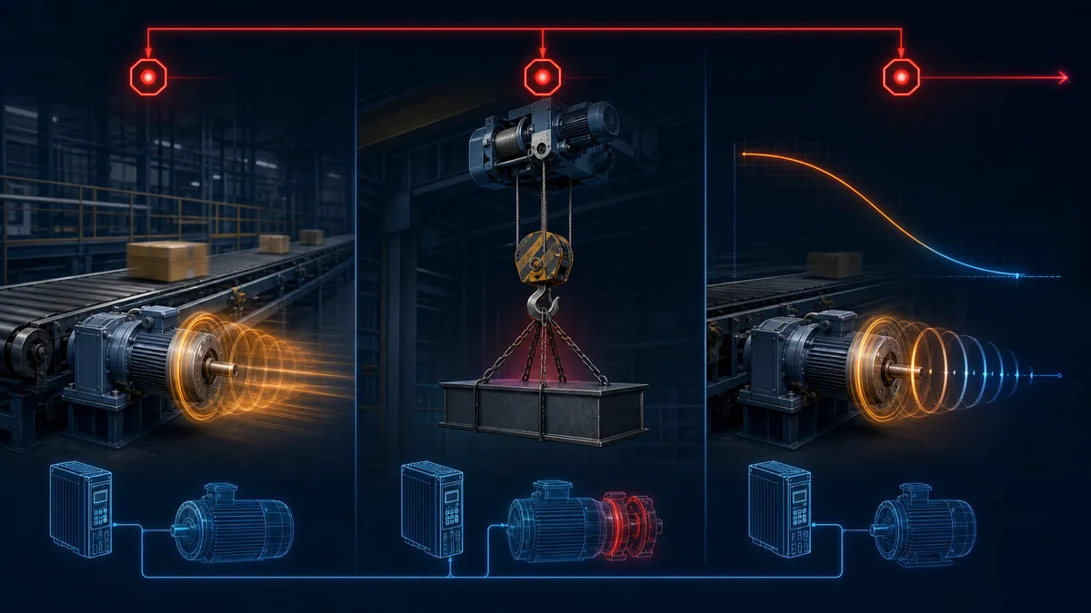
| Load | Failure to consider | Possible complementary measure | Test question |
|---|---|---|---|
| high-inertia fan | blades coast for minutes | guard locking, time/standstill monitoring | can access occur before hazard ends? |
| vertical hoist | load falls when torque disappears | suitable brake function, mechanical blocking | does every credible load remain controlled? |
| conveyor on incline | product or belt rolls backward | brake, backstop or controlled stop | what happens at maximum load and low friction? |
| spindle | stored kinetic energy remains | monitored stop, guard locking | what is worst stop time after relevant faults? |
| permanent-magnet motor | generated voltage while turning | isolation and discharge procedure | where can hazardous voltage remain? |
| pneumatic clamp | pressure remains after drive stop | separate safe exhaust/isolation design | can stored pressure release unexpectedly? |
Live mini-lab
Try it: press START, then STOP
A stop-dominant seal-in rung: START latches the motor output through its own contact, and STOP breaks the circuit.
Watch the output lamp: it stays on after START until you press STOP.
Free · no signup to try · runs in your browserOpens plcsimulationsoftware.com — same team
Dual-channel STO architecture, conceptually
Start from the safety function, not the terminals
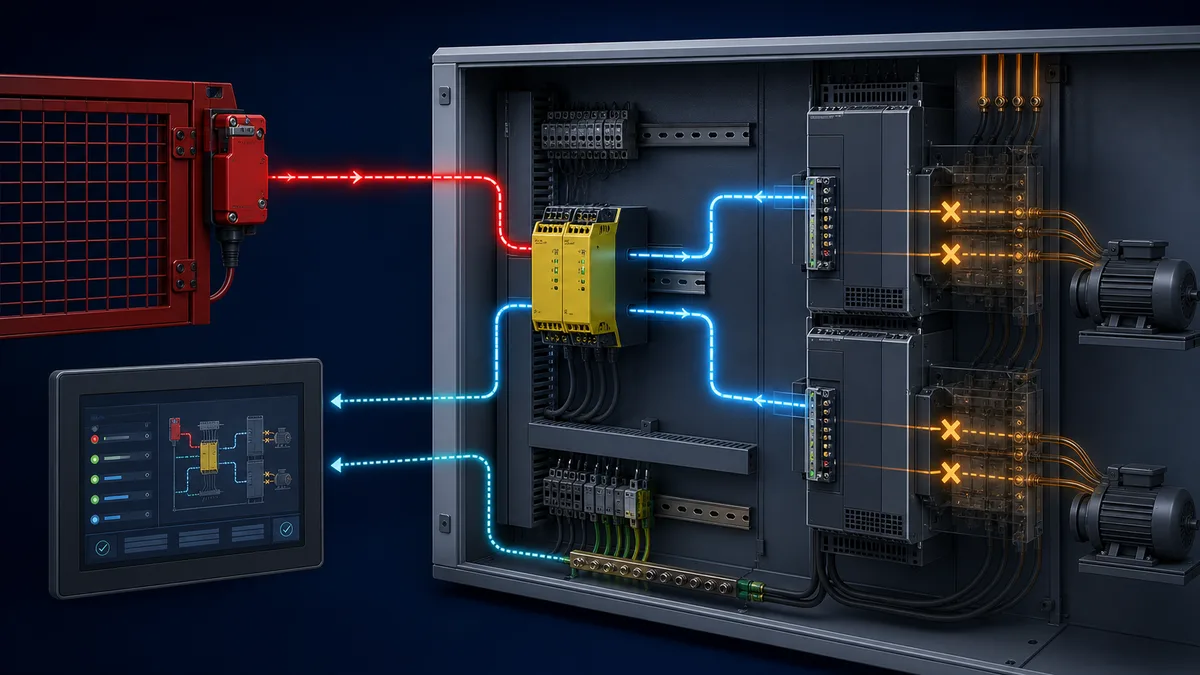
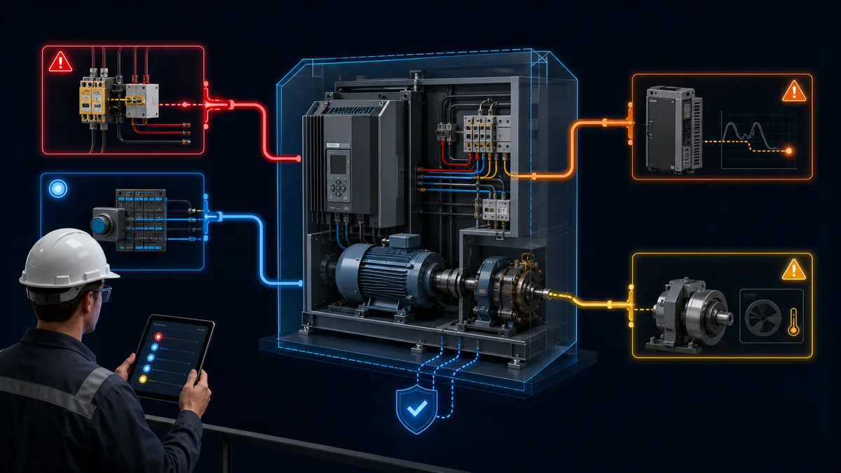
A common machine-safety chain has an input subsystem, logic subsystem and output subsystem. A guard switch, light curtain or emergency-stop device provides a demand; a safety relay or safety PLC evaluates channels and faults; the drive STO function is the final torque-prevention element. The required PLr or SIL is derived from the risk assessment and then verified for the complete chain.
ISO 13849-1:2023 provides a methodology for designing and integrating safety-related parts of control systems. ISO 12100:2010 provides the machinery risk-assessment and risk-reduction framework and remains the published edition while a replacement is under development. A product's maximum rating does not automatically establish the achieved rating of the system.
Two terminals do not prove redundancy
Many drives expose two STO inputs. Both normally have to be in the permissive state for the drive to produce torque, and removing either initiates STO. But the correct supply arrangement, output type, pulse testing, cable segregation, discrepancy timing, fault reaction and reset behavior vary. Copying terminal numbers or jumpers from a different model can defeat the function or damage equipment.
The installation design should answer:
| Design question | Why it matters | Required source |
|---|---|---|
| which hardware and firmware revision is installed? | safety data and supported functions can change | nameplate, configuration record, current manual |
| how are the channels energized and tested? | common-cause shorts or incompatible test pulses can invalidate diagnostics | drive and safety-output manuals |
| what happens when one channel changes alone? | discrepancy detection and reset behavior affect fault response | certified function description and test |
| may channels share a conductor or supply? | common-cause failure can defeat redundancy | architecture calculation and wiring rules |
| what feedback is safety-rated? | ordinary status bits may be diagnostic only | safety manual and system design |
| how is unexpected restart prevented? | a retained run command can create a new hazard | reset/restart requirement and negative test |
| what proof-test interval applies? | diagnostic assumptions depend on periodic testing | component data and validation plan |
STO and other drive safety functions
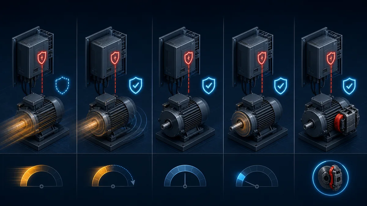
Modern drives may offer only STO or a larger certified motion-safety set. Names are standardized concepts, but availability and implementation remain product-specific.
| Function | Intended behavior | Useful when | Critical limitation |
|---|---|---|---|
| STO | inhibit torque production | standstill or safe coast is acceptable | does not control deceleration or hold load |
| SS1 | controlled stop followed by STO | uncontrolled coast creates unacceptable risk | stopping path and transition must be validated |
| SS2 | controlled stop followed by monitored operating stop | torque must remain to hold position | needs suitable monitored motion architecture |
| SOS | monitor standstill with torque available | setup/access requires stationary powered axis | not electrical isolation |
| SLS | monitor speed below a safe limit | reduced-speed setup or teaching | limit, reaction and access conditions require validation |
| SDI | monitor safe direction | reverse motion creates a hazard | does not by itself limit speed or position |
| SBC | provide a safe brake-control output | gravity or holding behavior needs a brake | brake mechanics and feedback still require analysis |
The Siemens SINAMICS S120 Safety Integrated manual illustrates how one drive family distinguishes basic and extended safety functions. Use that as evidence about that product family, not as a universal commissioning procedure.
Worked example: guarded conveyor with a VFD
Assume a conveyor is accessible through an interlocked gate. The risk assessment identifies crushing at the drive roller and determines that opening the gate must stop hazardous motion and prevent restart. A standard run command comes from the process PLC, while the safety function is implemented separately.
Define the requirement before choosing parts
The safety requirement specification records the initiating devices, zone, hazardous motion, required response, PLr or SIL target, maximum response time, reset behavior, restart prevention, diagnostics and validation cases. If the conveyor coasts longer than a person needs to reach the roller, STO alone does not satisfy the required behavior. The team might need controlled stopping, guard locking until standstill, or a mechanical solution.
Separate ordinary command from safety permission
The standard PLC may command run and speed and display safety diagnostics. The safety system evaluates the gate channels and drives the certified STO inputs. When the gate opens, the safety chain removes the drive's torque permission even if the standard run bit remains true. The HMI should distinguish at least: ordinary stop command, safety demand active, drive not ready, STO channel fault and final motor feedback.
Make reset and restart deliberate
Closing the gate should not automatically resume motion merely because a previous run request remains. The specified reset is performed from a position with appropriate visibility, and the machine requires a deliberate start action after the safety function resets. Large zones may require presence checks or other measures; a reset button is not a substitute for detecting someone inside.
| Step | Stimulus | Expected safety behavior | Evidence |
|---|---|---|---|
| 1 | normal ready, gate closed | drive can become ready only after valid reset/start sequence | state capture and feedback |
| 2 | open gate while running | torque prevention and stopping behavior meet requirement | response-time trace and stop measurement |
| 3 | close gate | no automatic hazardous restart | negative restart observation |
| 4 | reset with run request retained | system follows documented restart prevention | logic/status capture |
| 5 | interrupt channel A only | safe reaction and diagnosed discrepancy | fault record |
| 6 | interrupt channel B only | safe reaction and diagnosed discrepancy | fault record |
| 7 | simulate drive/communication diagnostic loss | safety claim remains independent of standard HMI data | observed state |
| 8 | restore after fault | controlled recovery requires defined actions | signed acceptance record |
Commissioning and validation workflow
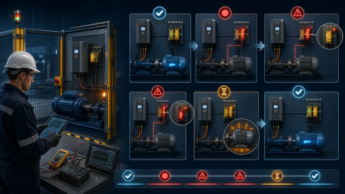
Validation is not “the motor stopped once.” It confirms the implemented safety function against its specification, including foreseeable faults and recovery behavior.
- Freeze the configuration. Record drive model, safety option, firmware, safety parameters, wiring revision and calculated safety data.
- Review the risk and safety requirements. Confirm the zone, hazard, initiating device, required performance, stop behavior, response time and reset rules.
- Inspect before energization. Verify conductors, protection, segregation, terminal torque, removed factory jumpers where applicable, shielding/grounding and diagram agreement under the site's safe-work procedure.
- Prove ordinary controls separately. Establish command source, enable, speed reference and motor rotation so control faults are not confused with safety faults.
- Test every demand device. Operate each guard, curtain or emergency-stop input and observe the complete response at the hazardous motion.
- Test each channel and diagnostic. Introduce faults only through the approved validation method; confirm safe reaction, discrepancy indication and recovery.
- Measure the stop. Use the defined measurement method at the worst credible operating condition, not a single unloaded observation.
- Test reset and restart negatives. Restore supplies, close guards and clear demands in different orders; hazardous motion must not resume contrary to the specification.
- Record results and deviations. Retain measured values, expected/observed states, equipment IDs, tester, date and disposition.
- Control changes. Reassess after drive replacement, firmware/configuration changes, brake changes, logic edits, new tooling or altered access.
Download the STO validation matrix
Download the 20-case Safe Torque Off validation matrix (CSV). Tailor it to the risk assessment, safety requirement specification, exact drive safety manual, machine mechanics and site procedures. It is an evidence organizer, not a safety design, calculation or certification.
Troubleshooting STO without bypassing safety
Troubleshooting begins with the declared state model. “Drive will not run” can mean an active safety demand, a channel discrepancy, a missing ordinary enable, a drive fault, an incorrect command source, an open brake circuit or a mechanical problem. Randomly restoring jumpers or forcing signals destroys evidence and can create hazardous motion.
| Symptom | Safe observations first | Likely branch | Do not assume |
|---|---|---|---|
| STO indicated active | demand-device state, both safety channels, safety-controller diagnostics | real demand, wiring open, channel discrepancy | bypassing the input is a diagnostic method |
| STO clears but drive not ready | ordinary enable, command source, drive fault and permissives | non-safety control path | STO is still the cause |
| one channel changes, other does not | safety input diagnostics and approved continuity test under isolation | conductor, output, terminal or device channel | channels can be tied together |
| motor coasts too long | speed, load, stopping-time record, brake/SS1 behavior | mechanics or stop-function selection | faster STO input changes coast physics |
| load drops on STO | brake command, brake feedback, holding capacity, load case | gravity-load design | motor torque can hold after STO |
| machine restarts after reset | retained run state, reset/start sequence, control-state ownership | restart logic | safety reset should equal process start |
| intermittent STO trip | time-stamped channel sequence, supply, cable and diagnostics | wiring, common-cause or test-pulse compatibility | clear-and-retry is a root cause |
| HMI says safe but drive runs | direct certified-state evidence and full chain test | wrong tag, stale diagnostic, mapping error | standard HMI status is safety evidence |
Use the VFD simulator to practise separating command source, enable, fault, ready and running evidence in a browser-based model. It cannot reproduce a real drive's certified STO circuitry, conductors, stop mechanics, brake, electrical hazards or achieved PL/SIL, so hardware safety validation remains mandatory.
Design and documentation checklist
| Artifact | Minimum useful content | Owner |
|---|---|---|
| risk assessment | tasks, people, hazards, risk estimates and reduction measures | machine safety team |
| safety requirement specification | function, trigger, response, PLr/SIL, timing, reset and diagnostics | responsible safety engineer |
| architecture calculation | subsystem data, categories, diagnostics, common cause, mission/proof intervals | competent designer |
| electrical drawings | exact terminals, supplies, conductor IDs, separation and feedback | electrical designer |
| drive safety configuration | hardware/firmware, enabled functions, parameters and checksum/signature where provided | authorized commissioner |
| stop measurement | method, instrument, operating cases, raw results and worst case | validation team |
| validation matrix | expected and observed normal/fault/recovery behavior | independent or designated validator |
| change record | trigger, impact review, retest scope and approvals | machine owner |
The ISO 13849-2 catalog record describes validation by analysis and testing for the safety functions, category and achieved performance of safety-related control-system parts. Use the applicable edition and local legal framework selected for the machine. For guarding and access decisions, use the machine-guarding owner; for optical access protection, use the safety light-curtain guide; for drive control and commissioning outside the safety claim, use VFD setup and wiring.
Diagnostic answer map for Safe Torque Off
| User or AI query | Concise answer | Required qualification |
|---|---|---|
| What does STO mean on a drive? | Safe Torque Off is a certified drive safety function that inhibits torque-producing energy and helps prevent unintended restart. | It does not by itself isolate incoming power, prove zero speed or remove stored energy. |
| Does STO stop a motor? | STO normally removes torque, so a moving load can coast to rest. | Required stop behavior depends on the risk assessment, mechanics and other safety functions. |
| Is STO an emergency stop? | STO can be the torque-removal element inside an emergency-stop design. | The complete function also includes initiation, logic, stopping behavior, reset and validation. |
| Is STO lockout/tagout? | No; STO is a control function and commonly leaves hazardous electrical energy present. | Covered servicing requires applicable energy-isolation law and site procedure. |
| Does STO hold a vertical load? | Not generally; removing torque can allow a gravity load to move. | A validated brake, blocking or safe-brake architecture may be required. |
| Why is a drive showing STO active? | A valid safety demand, open channel, missing supply, discrepancy, configuration state or wiring fault can assert STO. | Follow the approved diagnostic chain; never jumper or force a channel to clear it. |
| Can a normal PLC control STO? | Ordinary PLC I/O is not automatically suitable for a claimed safety function. | A safety PLC is suitable only within a complete designed and validated architecture. |
| What is the difference between STO and SS1? | STO removes torque and usually coasts; SS1 controls or monitors deceleration before transitioning to STO. | Exact implementation and fault response come from the certified drive function. |
| How is dual-channel STO wired? | Use the exact drive and safety-output manuals for both independent channels, supplies and diagnostics. | Two terminals alone do not prove redundancy, PL or SIL. |
| How is STO validated? | Test every demand, diagnosable fault, stop case, restart-prevention path, reset sequence and status mapping against the safety requirements. | Record versions, measured times, expected/observed results, deviations and approvals. |
Frequently asked questions
What is Safe Torque Off?
Safe Torque Off is a drive-integrated safety function that inhibits torque-producing energy to the motor and helps prevent unintended drive restart. It does not normally isolate the drive's electrical supply, discharge the DC bus, prove zero speed or hold a gravity load.
Does STO stop a motor immediately?
Not necessarily. If STO is selected while the motor is rotating, the load commonly coasts to rest. The actual stopping time depends on inertia, friction and load. If uncontrolled coast is unsafe, the risk assessment may require controlled stopping, guard locking, standstill monitoring or another measure.
Is STO the same as an emergency stop?
No. Emergency stop is a complementary protective measure initiated by a person and implemented with a defined stopping behavior. STO may be the torque-removal function used within that design, but the initiating device, logic, stop sequence, mechanics, reset and validation are all part of the complete emergency-stop function.
Is STO the same as lockout/tagout?
No. STO is control circuitry and usually leaves hazardous electrical and other stored energy present. Lockout/tagout uses energy-isolating devices and a controlled procedure for covered servicing or maintenance. Follow the applicable legal and site procedure rather than treating an STO indication as isolation.
Does STO hold a suspended load?
No general STO claim guarantees holding. With torque removed, a vertical or unbalanced load may move under gravity. A suitable brake architecture, Safe Brake Control or mechanical blocking may be required, and the brake mechanics, feedback and load cases must be validated.
How is dual-channel STO wired?
It is wired exactly as the installed drive and safety-output manuals require. Many drives use two independent safety inputs, but supplies, pulse tests, conductor separation, discrepancy behavior and reset rules differ. A conceptual dual-channel diagram cannot replace the model-specific terminal drawing and system calculation.
Can a standard PLC control STO?
Ordinary PLC I/O is not automatically suitable for a claimed safety function. A safety PLC may be suitable when its CPU, I/O, program, communications and complete architecture are designed and validated for the required PL or SIL. A standard PLC can often mirror status for diagnostics without being part of the safety decision.
What is the difference between STO and SS1?
STO inhibits torque and normally lets existing motion coast. Safe Stop 1 performs or monitors a controlled deceleration and then transitions to STO. The exact SS1 behavior, timing and fault response are defined by the drive's certified safety implementation.
Why is my drive showing STO active?
Check the approved diagnostic path for the demand device, both safety channels, safety-controller state and drive safety status. An open guard, pressed emergency stop, missing channel supply, discrepancy, configuration state or wiring fault can all be valid causes. Do not fit a jumper or force a signal to make the message disappear.
How should Safe Torque Off be tested?
Validate it against the safety requirement specification: every initiating device, each diagnosable channel fault, worst-case stopping behavior, restart prevention, restoration sequence, status mapping and applicable proof-test case. Record expected and observed results, equipment versions, measured times, deviations and approvals.
Sources, review scope, and limitations
The PLC Programming IO Editorial Team reviewed this guide on August 30, 2026 against the cited machinery-safety standards catalog records, OSHA sources and current drive manuals. Standards editions, law, drive certification, firmware and terminal behavior are product- and jurisdiction-specific. The installed risk assessment, safety requirement specification, achieved PL/SIL calculation, exact current manuals and recorded validation remain authoritative.
- ISO 12100:2010 — machinery risk assessment and risk reduction
- ISO 13849-1:2023 — safety-related control-system design and integration
- ISO 13849-2:2012 — validation by analysis and testing
- IEC 61800-5-2 — adjustable-speed drive functional-safety requirements
- OSHA 29 CFR 1910.147 — control of hazardous energy
- OSHA machine-guarding eTool
- OSHA relationship between lockout/tagout and machine guarding
- Rockwell Automation PowerFlex 520-series user manual, September 2025
- Siemens SINAMICS S210 Safety Integrated commissioning manual
- Siemens SINAMICS S120 Safety Integrated function manual
- Siemens SINAMICS engineering manual
This guide is educational and vendor-neutral. It deliberately does not provide terminal numbers, conductor sizes, jumpers, safety parameter values, fault exclusions, PL/SIL calculations, safe-distance results or approval for a particular machine. Industrial drives expose hazardous voltage and stored energy, and unexpected motion can kill. Only qualified and authorized people working from the exact current manuals, engineered drawings, machinery risk assessment, safety requirement specification, applicable law and site safe-work procedures should design, install, commission, test or modify a safety function.
Now run it · free · no signup
Enable a VFD and set its speed in your browser
Give the drive run permission, set a speed reference and stop it safely while watching live frequency and motor speed. No signup required to finish the lab.
Ownership disclosure: PLC Programming IO and PLC Simulation Software are operated by the same publisher.
PLC Programming IO Editorial Team
Industrial automation education, references, and software testing
The PLC Programming IO Editorial Team publishes sourced industrial-automation education and documents how material is reviewed, tested, and corrected. A team byline means the publisher is responsible for the page; it does not represent a fictional person or imply an engineering licence.
Coverage:
- • PLC programming concepts and examples
- • Vendor software tutorials and comparisons
- • SCADA, HMI, protocols, and instrumentation
- • Training, careers, and reference material
Review standard:
- • Prefer primary and official sources
- • Record software versions when material
- • Separate tested facts from estimates
- • Publish material corrections
Important scope note
This site provides education, not project-specific engineering approval. Safety, code, and compliance decisions require a qualified person with access to the actual machine and jurisdiction.