75 Industrial Automation Interview Questions & Answers (2026)
Prepare for industrial automation, automation engineer and controls interviews with 75 technically grounded questions on PLCs, SCADA, HMI, networking, troubleshooting and system design.
Quick answer: Industrial automation interviews test three broad capabilities: a sound technical model, the ability to apply it to a real control system, and safe engineering judgment under incomplete information. Prepare PLC execution and I/O, instrumentation and control, HMI/SCADA, industrial networks, troubleshooting, system design and evidence from work you personally completed. These 75 questions are original practice prompts—not recalled employer tests or a promise that every employer uses the same assessment.
Landing an automation engineer or controls engineer role requires more than reciting definitions. A useful technical interview exposes whether a candidate can model a system, identify the first discriminating observation, communicate uncertainty and respect safety and authorization boundaries. This guide groups common, role-relevant prompts into a repeatable practice sequence; the vacancy and employer remain the source of truth for the actual assessment.
The questions here span entry-level fundamentals through senior system design scenarios. If you are interviewing for a controls engineer, control engineer, PLC engineer, SCADA engineer or system-integrator role, the underlying disciplines overlap, but the weighting changes with the job description and installed systems. Use the role map below to choose depth, then practise the scenario sections aloud.
| Target role | Highest-value topics | Evidence to prepare | Typical weak signal |
|---|---|---|---|
| maintenance or automation technician | drawings, I/O path, electrical boundaries, safe fault isolation | one redacted signal trace and restoration record | replacing a part from an alarm description |
| PLC or automation engineer | scan/task behavior, reusable code, HMI, drives, networks and commissioning | requirement-to-code-to-test traceability | naming instructions without explaining state |
| controls or process-control engineer | instrumentation, PID, P&IDs, alarm management and failure behavior | loop narrative, trend or controlled tuning example | treating every bad loop as a tuning problem |
| SCADA or OT engineer | tag quality, historians, OPC UA, network architecture and access control | data-path diagram and diagnosis evidence | assuming displayed data is fresh and verified |
| senior or lead engineer | architecture, safety boundaries, cybersecurity, reviews and lifecycle decisions | decision record, FAT/SAT evidence and change-control example | presenting vendor preference as engineering proof |
Interview prep resource: The PLC Programming Code Pack includes 200+ practice problems, annotated ladder logic examples, and mock technical scenarios used in real automation interviews.
Table of Contents
- How Automation Engineer Interviews Work
- Fundamentals Questions (15)
- PLC Programming Questions (15)
- SCADA and HMI Questions (10)
- Communication and Networking Questions (10)
- System Design Questions (10)
- Troubleshooting Scenario Questions (10)
- Behavioral and Soft Skills Questions (5)
- Questions You Should Ask the Interviewer
- Interview Preparation Checklist
- Technical Sources and Edition Boundaries
- Frequently Asked Questions
How Automation Engineer Interviews Work
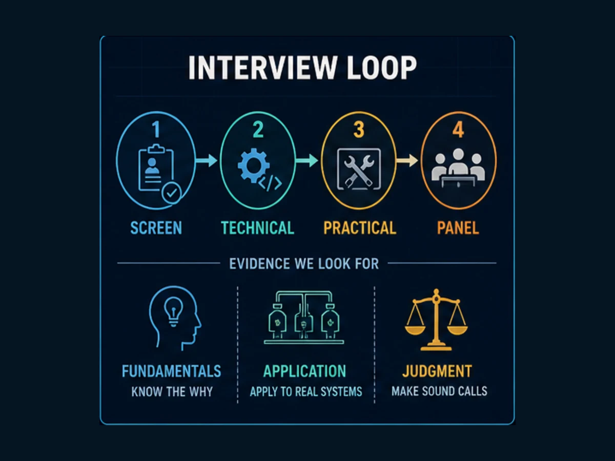
Most automation and controls engineer interviews follow a four-stage structure. Knowing the format in advance lets you calibrate your energy and preparation for each stage rather than treating the whole process as one undifferentiated event.
The Typical Process
Stage 1 — Phone Screen (30–45 minutes) Usually with an HR recruiter or a technical team lead. Expect high-level experience verification, a few basic technical questions (can you name the IEC 61131-3 languages, what platforms have you used), and salary alignment. Your goal here is to get to the technical round — keep answers concise and concrete.
Stage 2 — Technical Interview (60–90 minutes) This is where it gets real. A controls engineer or engineering manager walks through your resume and asks increasingly specific technical questions. Expect to be pushed: if you say you know PID, they will ask you to explain integral windup. If you mention PROFINET, they will ask how it differs from EtherNet/IP. Have depth behind every claim on your resume.
Stage 3 — Practical Test or Working Session (60–120 minutes) Many companies — especially OEMs and system integrators — include a hands-on round. This may be a live programming exercise in Studio 5000 or TIA Portal, a P&ID interpretation task, a troubleshooting scenario with a simulated fault, or a written technical problem. If you do not know which platform they use, ask before this round so you can review the software.
Stage 4 — Panel or Final Interview (45–60 minutes) You meet more stakeholders: project managers, senior engineers, sometimes a safety or reliability engineer. Behavioral questions dominate here. The technical bar is lower, but the communication bar is higher. This round determines cultural fit and whether you can represent the engineering team to non-technical stakeholders.
What Hiring Managers Actually Evaluate
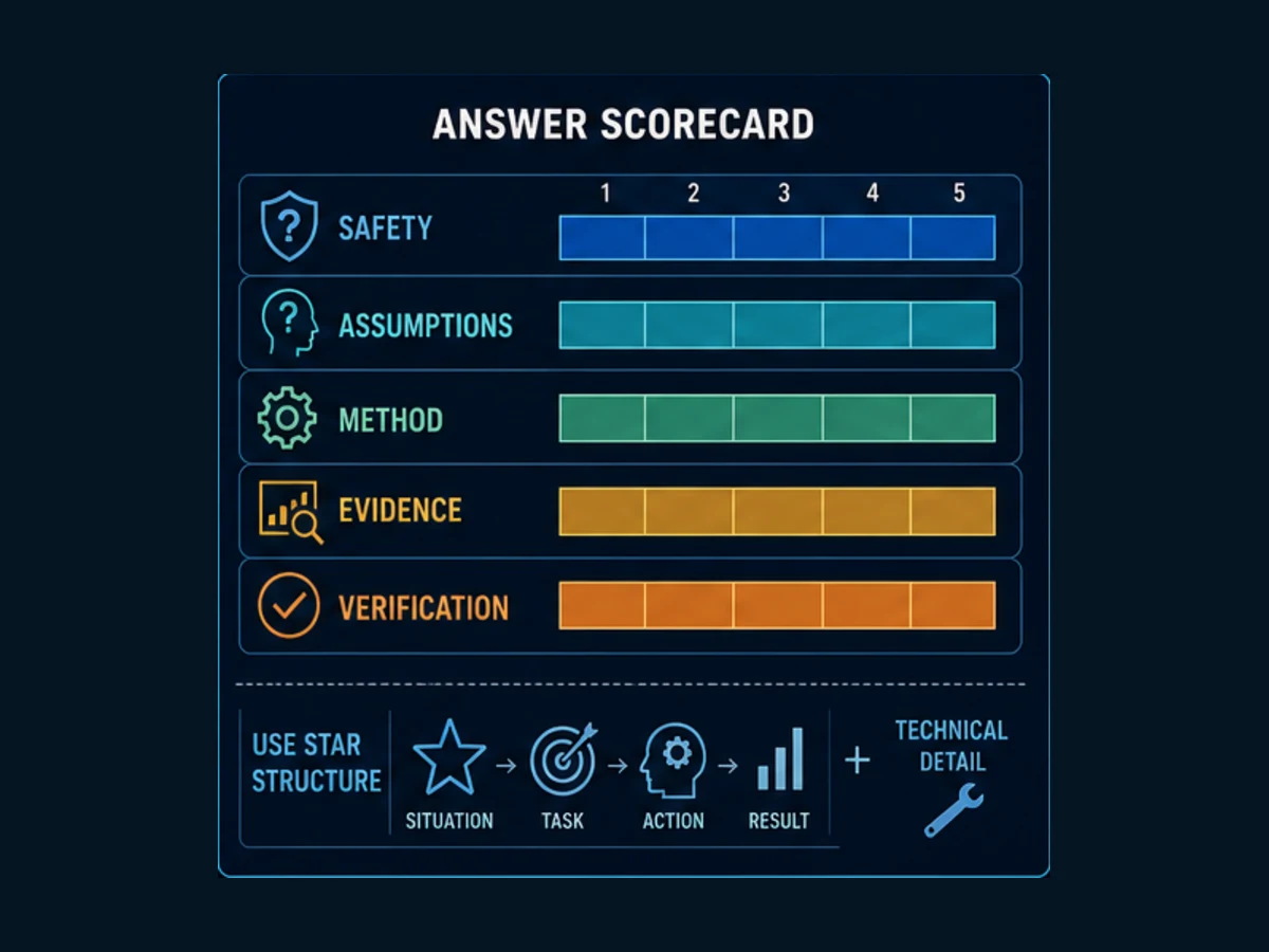
Across all rounds, experienced automation hiring managers consistently score candidates on three dimensions:
Technical foundation. Do you know the fundamentals cold? Can you explain why a seal-in circuit works without drawing a picture? Can you describe what happens to a PID loop when integral gain is too high? Shallow answers get filtered out quickly.
Engineering judgment. Technical knowledge is necessary but not sufficient. What interviewers want to see is that you make sensible decisions under incomplete information — that you ask the right clarifying questions, that you know when to use a standard solution versus a custom one, and that you understand the risk implications of your choices.
Communication. Automation engineers rarely work alone. You will interface with mechanical engineers, electricians, operators, and plant managers. Interviewers listen for your ability to explain complex concepts clearly, to acknowledge uncertainty honestly, and to push back respectfully when you disagree. The candidate who says "I am not sure, but here is how I would find out" is more hireable than the one who bluffs.
Fundamentals Questions
These 15 questions cover foundations that recur across many automation roles. The exact wording, depth and platform assumptions vary. A senior candidate should answer the direct question concisely, then volunteer the one exception that materially changes the engineering decision.
Q1. What is a PLC and how does it work?
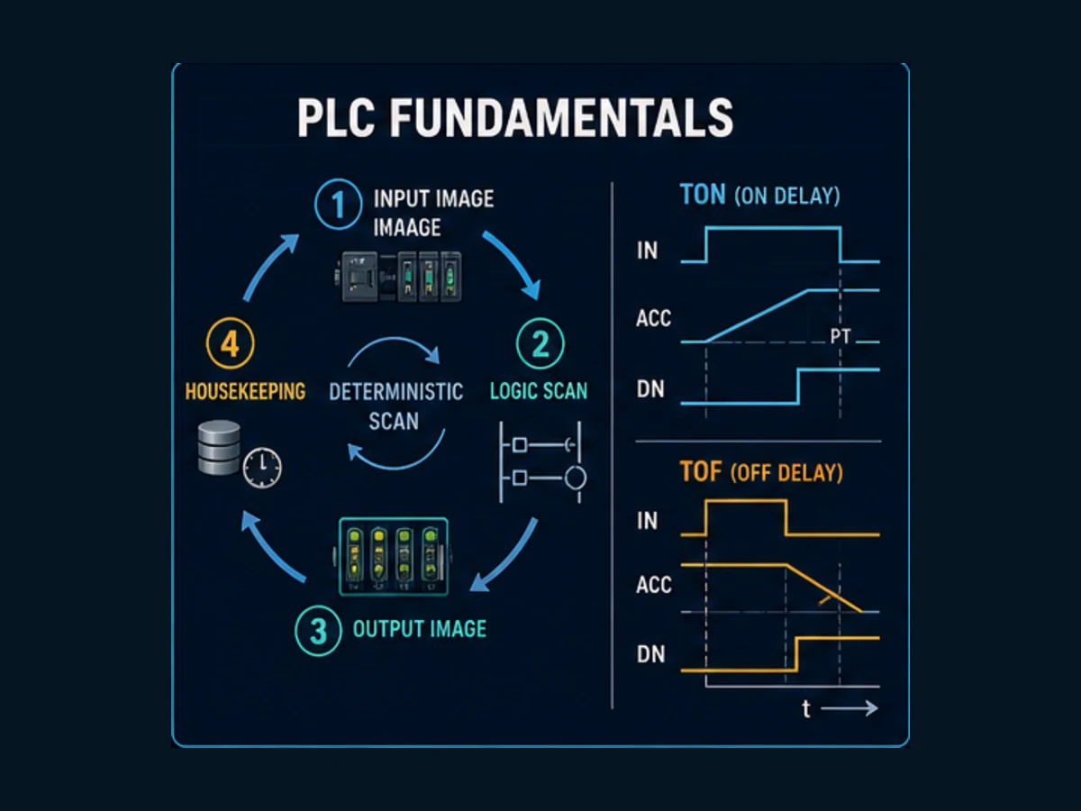
Model answer: A programmable logic controller is an industrial digital control system that executes user logic and interacts with field I/O under defined timing, environmental and reliability constraints. In a simple cyclic model it samples or updates inputs, executes scheduled logic, updates outputs and performs communications and diagnostics. Modern controllers may also use periodic or event tasks, asynchronous network I/O and platform-specific process-image behavior, so the exact response time and update order must come from the controller configuration and manual—not from a universal 5–20 ms assumption.
Why they ask this: It is a baseline qualifier. A poor answer reveals that a candidate has worked around PLCs without understanding them. A strong answer — particularly mentioning determinism — signals real engineering understanding.
Q2. Explain the PLC scan cycle in detail.
Model answer: Start with the simple cyclic model: the controller captures an input image, executes scheduled logic, transfers an output image and performs communications or housekeeping. That model is valuable for tracing a beginner program, but it is not universal. Some controllers update network I/O asynchronously, run several tasks at different priorities, expose immediate I/O operations or apply different process-image rules. State the simple model, name the target platform exception, and use a timestamped trace to prove when a physical input, controller-visible value, task and output actually changed.
Why they ask this: Misunderstanding the image table concept leads to real bugs. Interviewers want to see you articulate this correctly, especially if you are claiming mid-level or senior experience.
Q3. What is the difference between a normally open (NO) and normally closed (NC) contact?
Model answer: A normally open contact passes current only when the associated coil or input is energized — it is open at rest. A normally closed contact passes current when its associated coil or input is de-energized — it is closed at rest. In ladder logic, a normally closed contact on an emergency stop input is the preferred design because a wire break, blown fuse, or loss of power to the E-stop button will open the contact and de-energize the output, achieving a fail-safe condition. Using a normally open contact for safety-critical functions like E-stops is a common beginner mistake that can be dangerous.
Why they ask this: Beyond the simple definition, they want to see you apply the fail-safe reasoning. The candidate who explains why NC contacts belong on E-stops demonstrates safety-conscious engineering thinking.
Q4. Which programming languages does IEC 61131-3 define?
Model answer: Answer with the edition boundary. IEC 61131-3:2025 defines Structured Text (ST), Ladder Diagram (LD) and Function Block Diagram (FBD), with Sequential Function Chart (SFC) elements for structuring programs and function blocks. The withdrawn 2013 edition also listed Instruction List (IL), which is why older courses still ask for “five languages.” A strong answer notes that language choice follows the task and team: LD can make discrete interlocks reviewable, ST suits algorithms and data manipulation, FBD makes signal flow visible, and SFC can structure sequences. The current IEC publication page is the edition reference.
Why they ask this: This question quickly separates candidates who have read about PLCs from those who have programmed them. Knowing which language fits which use case — not just the list — is what interviewers want to hear.
Q5. Explain the difference between a TON and TOF timer.
Model answer: A TON (Timer ON-Delay) starts counting when the enable input goes true. The done bit energizes only after the programmed time period has elapsed with the input remaining true. If the input goes false before the timer completes, it resets to zero. A TOF (Timer OFF-Delay) energizes its done bit immediately when the enable input goes true, then begins counting when the input goes false. The done bit de-energizes only after the programmed delay has elapsed with the input remaining false. TON is used when you want a delayed start — for example, a motor seal-in after a soft-start period. TOF is used when you want a delayed stop — for example, a cooling fan that continues running for 30 seconds after the motor it cools has stopped.
Why they ask this: Timer misuse is one of the most common causes of machine behavior complaints. Interviewers want to see practical application, not just definitions.
Q6. What is a PID controller and what do the three terms do?
Model answer: PID stands for Proportional-Integral-Derivative. It is a feedback control algorithm that continuously calculates an error value — the difference between a desired setpoint and a measured process variable — and applies a corrective output to minimize that error. The Proportional term produces an output proportional to the current error: larger error, larger correction. On its own, P control leaves a steady-state offset. The Integral term accumulates the error over time, eliminating the steady-state offset that pure P control leaves behind. Too much integral gain causes integral windup and oscillation. The Derivative term responds to the rate of change of error, providing predictive damping that reduces overshoot. Most industrial processes are tuned using PI control; derivative is added only when process dynamics require it because it amplifies noise.
Why they ask this: PID is foundational. Interviewers expect you to explain windup and derivative noise sensitivity — candidates who only recite the three terms without context are not ready for a mid-level role.
Q7. What is the difference between a discrete input and an analog input?
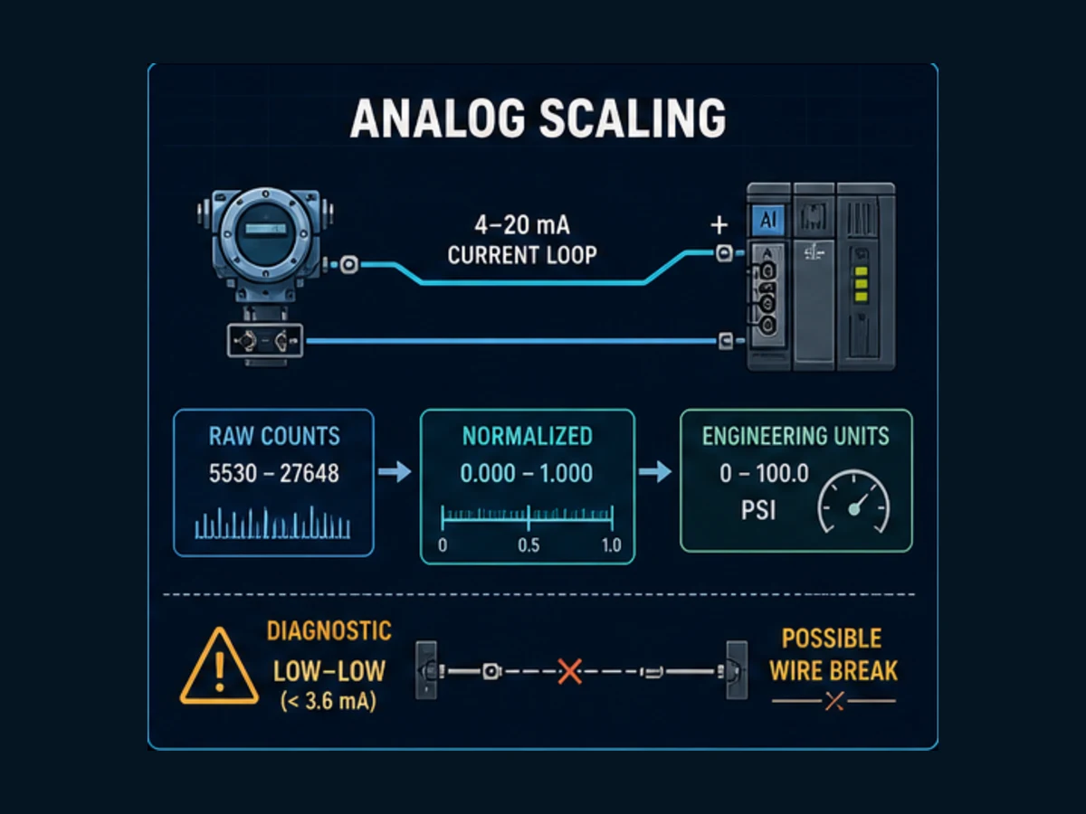
Model answer: A discrete input has only two states: on or off, represented as a single bit (1 or 0). Examples include limit switches, pushbuttons, proximity sensors, and photoelectric sensors. An analog input represents a continuous range of values — typically a 4–20 mA current signal or 0–10 VDC voltage signal from a sensor such as a pressure transmitter, thermocouple, or flow meter. The PLC's analog input module converts this signal to a raw integer value (commonly 0–32767 for a 15-bit input module) which the program then scales to engineering units using a linear conversion formula. The 4 mA live-zero standard is important: 0 mA indicates a broken wire or instrument failure, while 4 mA indicates zero of the process range.
Why they ask this: Analog I/O handling — including scaling and live-zero diagnostics — is a daily reality in process control. This question filters candidates who have only worked on purely discrete applications.
Q8. What is a safety integrity level (SIL) and why does it matter?
Model answer: SIL is a measure of the risk reduction provided by a safety instrumented function (SIF) as defined in the IEC 61508 and IEC 61511 standards. SIL levels range from SIL 1 (lowest, approximately 10x risk reduction) to SIL 4 (highest, approximately 10,000x risk reduction). The SIL level required for a specific function is determined through a process hazard analysis — methods like LOPA (Layer of Protection Analysis) or FMEA are used. In practice, most automation engineers encounter SIL 1 and SIL 2 requirements in process industries. A SIL-rated safety instrumented system requires separate hardware, validated software, proof testing at defined intervals, and documentation that would not typically be required for a standard control system.
Why they ask this: Safety awareness is non-negotiable in most industrial environments. Even if you are not designing safety systems, you need to know when a safety engineer needs to be involved.
Q9. What is the difference between a relay output and a transistor output on a PLC?
Model answer: A relay output uses a physical electromechanical relay contact to switch the load. It can switch both AC and DC loads, handles higher current (typically 2–5A per point), and provides electrical isolation. The tradeoff is switching speed — relays operate in the 5–15 millisecond range, have a limited mechanical life (typically 100,000 to 1,000,000 operations), and generate more electrical noise. A transistor output (also called solid-state output) uses a transistor to switch DC loads only. It switches much faster (microseconds), has no moving parts, handles lower continuous current (typically 0.5–1A), and is suitable for high-frequency switching applications like stepper motor pulses or high-speed counting. Choosing the wrong output type for the load type is a common commissioning mistake.
Why they ask this: Output selection errors cause wiring problems and hardware damage in the field. This question tests practical hardware knowledge.
Q10. What is the purpose of a watchdog timer in a PLC?
Model answer: A watchdog timer is a hardware or software timer that the PLC processor must reset within a defined interval during each scan cycle. If the processor fails to reset the watchdog — because of a software fault, infinite loop, or hardware failure — the timer expires and forces the PLC into a fault state, de-energizing outputs and placing the system in a safe state. Watchdog timers are a fundamental fail-safe mechanism: they ensure that a controller that has crashed or hung does not leave outputs energized indefinitely, which could cause equipment damage or safety hazards. Many PLCs allow the programmer to configure the watchdog timeout value to match the expected scan time.
Why they ask this: Interviewers use this question to probe your understanding of why PLCs are trusted in safety-critical applications — it is about the system design philosophy, not just a feature list.
Q11. Explain the difference between local I/O and remote I/O.
Model answer: Local I/O refers to input/output modules installed in the same chassis or rack as the PLC processor. They connect directly to the processor backplane and are scanned every cycle with minimal latency. Remote I/O — also called distributed I/O — consists of I/O modules located away from the main processor, connected via a communication network such as EtherNet/IP, PROFINET, PROFIBUS, or DeviceNet. Remote I/O introduces network-based latency and requires configuring a communications adapter at the remote location. It is used when field devices are physically distant from the control panel, when large I/O counts require distributing hardware across a machine, or when the application benefits from running I/O cabling in a ring or star topology to reduce overall wire runs.
Why they ask this: Remote I/O is ubiquitous in modern machine design. Not knowing the tradeoffs signals a candidate who has only worked on small, simple applications.
Q12. What is a fieldbus and why was it developed?
Model answer: A fieldbus is a digital communication network that connects field devices — sensors, actuators, drives, transmitters — to a control system, replacing traditional point-to-point analog wiring. It was developed in the 1980s and 1990s to address the limitations of 4–20 mA analog signals: analog signals carry only one value per wire pair, require individual home runs to the control panel, and cannot transmit device diagnostics. Fieldbus networks like PROFIBUS, DeviceNet, and Foundation Fieldbus allow multiple devices to share a single cable, communicate digitally with higher accuracy, and report device health status back to the controller. The downside is increased configuration complexity and the need for specialized commissioning knowledge.
Why they ask this: Understanding why fieldbuses exist — not just how to configure them — shows engineering maturity.
Q13. What does a 4–20 mA signal represent, and what is the advantage of 4 mA as the live zero?
Model answer: A 4–20 mA current loop signal is the standard for transmitting process values from field instruments to a controller. The signal represents the full engineering range of the instrument: 4 mA corresponds to 0% of the process range (e.g., 0 psi, 0°C) and 20 mA corresponds to 100% (e.g., 100 psi, 200°C). The live zero — using 4 mA rather than 0 mA to represent zero — is deliberate: a true zero milliamp reading indicates a broken wire, power failure, or instrument fault, and can be used to trigger a diagnostic alarm. If 0 mA were used as the zero point, a broken wire would be indistinguishable from a valid zero reading, making fault detection impossible. This live-zero principle is fundamental to process instrumentation design.
Why they ask this: Analog instrumentation is everywhere in process control. This question checks whether you understand the design intent behind the standard, not just the signal range.
Q14. What is the difference between a PLC and a DCS?
Model answer: A PLC (Programmable Logic Controller) was originally designed for discrete, high-speed, sequential control applications — machine control, conveyor systems, packaging lines. A DCS (Distributed Control System) was designed for continuous process control in applications like oil refining, chemical plants, and power generation, where the emphasis is on regulatory control loops, historian integration, and large I/O counts distributed across a plant. Modern PLCs and DCS systems have converged significantly — today's high-end PLCs handle continuous control very well, and some DCS platforms handle discrete control adequately. The remaining differences are primarily in engineering philosophy: DCS systems tend to be more prescriptive with built-in process control function blocks, unified configuration environments, and tighter integration between the controller, historian, and operator interface. PLCs offer more flexibility and are generally more cost-effective for smaller applications.
Why they ask this: Candidates applying for process industry roles especially need to know this distinction. It also reveals how broadly the candidate has thought about control system architecture.
Q15. What is a P&ID and what information does it contain?
Model answer: A P&ID — Piping and Instrumentation Diagram — is the primary engineering document that describes a process system. It shows all process piping, equipment (vessels, pumps, heat exchangers), instrumentation (transmitters, valves, switches), and their interconnections. Each instrument is identified by a tag number following ISA-5.1 conventions, which encodes the measured variable and instrument function — for example, FIC-101 identifies a Flow Indicating Controller with tag number 101. P&IDs also show control loops, interlocks, and the interfaces between the field instruments and the control system. For an automation engineer, a P&ID is the primary source of truth for what needs to be controlled, what interlocks are required, and what alarms need to be configured. Being able to read a P&ID fluently is a basic professional competency.
Why they ask this: If you cannot read a P&ID, you cannot do the job in a process industry environment. This question is a quick filter for candidates targeting process control or oil and gas roles.
PLC Programming Questions
These 15 questions target candidates claiming PLC programming experience — typically mid-level and above. For entry-level roles, expect a subset of these alongside the fundamentals questions.
Q16. How would you program a motor start/stop circuit with a seal-in?
Model answer: The classic motor start/stop ladder rung uses two rungs. The first rung has the start pushbutton (NO contact) in series with a normally closed stop pushbutton, energizing the motor output coil. In parallel with the start pushbutton contact, you add a normally open contact of the motor output coil itself — this is the seal-in, or holding contact. Once the motor output energizes, the seal-in contact holds the rung true even after the operator releases the start button. Pressing the stop pushbutton (wired NC) opens the rung, de-energizes the output coil, and opens the seal-in contact. The motor stays off until start is pressed again. In modern Allen-Bradley and Siemens implementations, you also need to handle overload relay feedback, interlock conditions, and typically add a run status feedback bit from the motor drive for confirmation.
Why they ask this: This is the canonical test of basic ladder logic competency. Anyone claiming PLC programming experience should answer this in under 60 seconds.
Q17. Explain the difference between an AOI and a subroutine in Allen-Bradley Studio 5000.
Model answer: Both AOIs and subroutines promote code reuse, but they work differently. A subroutine is a separate program section (a JSR/RET pair) that you jump to from a main program. It shares the same data scope as the calling program and does not have its own data structure — all tag access is through the global or local program tag database. An AOI (Add-On Instruction) is a reusable, encapsulated instruction block with its own defined parameters, local tags, and optional state machine. Once defined, an AOI appears in the instruction set and can be instantiated multiple times with different tag instances, each maintaining its own data independently. AOIs are the preferred pattern for device abstraction — for example, a motor starter AOI that encapsulates all the logic, interlocks, and state management for a single motor, instantiated once per motor in the application. The encapsulation and multi-instance capability of AOIs is what makes them architecturally superior to subroutines for modular machine code.
Why they ask this: AOI usage separates experienced Studio 5000 programmers from beginners. This answer also demonstrates knowledge of software architecture principles, not just PLC features.
Q18. How do you scale an analog input from raw counts to engineering units?
Model answer: The standard linear scaling formula is: EU = (Raw - RawMin) / (RawMax - RawMin) × (EUMax - EUMin) + EUMin. For a 4–20 mA input on a module that outputs 6,242–31,208 counts (Rockwell 1756-IF16), a pressure transmitter ranged 0–100 psi would scale as: PSI = (Raw - 6242) / (31208 - 6242) × 100. Many PLC platforms provide built-in scaling instructions — Allen-Bradley has the SCL instruction and Studio 5000 provides the CPT instruction with the formula inline. In Siemens TIA Portal, the NORM_X and SCALE_X function blocks handle this. The important considerations are: always confirm the module's raw count range from the module manual (it varies by module and configuration), account for the live-zero offset in the raw count range so that a broken wire reads below the minimum, and apply input filtering for noisy signals before scaling. Documenting the scaling parameters clearly in the program comments is essential for maintenance.
Why they ask this: Analog scaling is a daily task in process control programming. Getting the raw count range wrong is one of the most common causes of incorrect engineering unit display.
Q19. What is indirect addressing and when would you use it?
Model answer: Indirect addressing allows a program to access a memory location using a variable index rather than a fixed address. Instead of reading from a specific fixed register, you read from the register whose address is stored in another variable. In Allen-Bradley ControlLogix, this is done using the array subscript pattern: instead of Motor[2].Speed, you might use Motor[MotorIndex].Speed where MotorIndex is a DINT tag. In Siemens Step 7 classic, indirect addressing used pointer arithmetic with area codes. The primary use case is building loops and tables — for example, iterating through an array of 24 motor tags using a FOR loop with an index variable, rather than writing 24 identical rungs with hard-coded tag names. It enables generic, scalable code patterns and is particularly valuable in large applications with repetitive machine sections.
Why they ask this: Indirect addressing separates programmers who write scalable code from those who write copy-paste code. The ability to articulate a real use case shows practical programming maturity.
Q20. Explain the difference between Function Blocks and Function Calls in Siemens TIA Portal (FBs vs FCs).
Model answer: In Siemens TIA Portal, FCs (Function Calls) are stateless — they execute logic and can return a value, but they do not have associated memory that persists between calls. All working data must be passed through parameters. FBs (Function Blocks) have an associated instance data block (DB) that retains state between scan cycles. When you call an FB, you specify its instance DB, and any static variables declared in the FB retain their values from one call to the next. This makes FBs suitable for anything that needs to remember state — timers, counters, motor control objects, PID controllers. FCs are appropriate for stateless calculations — unit conversions, alarm limit checking, mathematical operations that do not need memory. The FB/instance DB pattern in TIA Portal is directly analogous to object-oriented classes and instances, and understanding this parallel is useful for designing scalable Siemens programs.
Why they ask this: FB vs FC confusion leads to runtime errors (particularly timer and counter problems) in Siemens code. This is a must-know for anyone claiming TIA Portal experience.
Q21. How do you handle a totalizer or accumulator in PLC code?
Model answer: A totalizer accumulates a running sum of a rate-based value over time — for example, total flow in gallons from a flow meter that outputs gallons per minute. The basic pattern uses a one-shot trigger on a periodic interrupt or a timer-triggered calculation: Accumulated Total += (Flow Rate × Scan Time / 60). In Allen-Bradley, this is typically implemented in a periodic task running at a fixed interval to ensure consistent integration. You need to handle rollover (what happens when the accumulator exceeds its data type maximum), provide a reset mechanism, and store the accumulated value to non-volatile memory or historian if it needs to survive a power cycle. For custody transfer or billing applications, the totalizer must meet additional accuracy and tamper-protection requirements. Using a dedicated flow totalizer transmitter is preferable to software totalization for high-stakes applications.
Why they ask this: Totalizers expose whether a candidate understands time-based integration and the practical issues of scan time variability, data type overflow, and persistence.
Q22. What is a one-shot instruction and why is it important?
Model answer: A one-shot instruction (OSR — One Shot Rising, or OSF — One Shot Falling in Allen-Bradley) energizes its output for exactly one scan cycle when its input transitions from false-to-true (OSR) or true-to-false (OSF). After that single scan, the output bit de-energizes regardless of the input state, and will not energize again until the input completes another transition. One-shots are critical for edge-detection logic — triggering an event on a button press rather than for the entire duration the button is held, loading a recipe value on a mode change, or capturing data to a register on a sensor rising edge. Without one-shots, any logic that should trigger on a transition would trigger continuously for as long as the input remains true, causing repeated operations, counter errors, or corrupted recipe loads.
Why they ask this: Misuse of one-shots — or failing to use them when needed — is a frequent source of intermittent bugs. This is a practical skills marker.
Q23. How do you implement a state machine in ladder logic?
Model answer: The most reliable pattern for a state machine in ladder logic uses a DINT tag (e.g., Machine_State) to hold the current state number, with one rung group per state. Each rung group begins with an examination of Machine_State equal to the state number, executes the logic for that state, and writes to Machine_State with a new value when transition conditions are met. For example, State 0 is IDLE, State 1 is STARTING, State 2 is RUNNING, State 3 is FAULTED. The IDLE state monitors the start command; when met, it writes 1 to Machine_State. The STARTING state monitors the motor run feedback; when received, it writes 2. This pattern is clean, auditable, and easy for maintenance technicians to follow. In Siemens TIA Portal, the same pattern works in Structured Text with a CASE statement, which is cleaner for complex state machines. IEC 61131-3 SFC is the language specifically designed for this pattern when multiple parallel sequences are involved.
Why they ask this: State machine design is fundamental to machine control. Candidates who cannot articulate this pattern have limited architectural experience.
Q24. What is program organization in Allen-Bradley Studio 5000, and how do you structure a large application?
Model answer: Studio 5000 organizes code into Tasks, Programs, and Routines. A Task is the execution scheduler — you can define Continuous, Periodic, or Event tasks, each with a configurable priority. A Program belongs to a Task and has its own local tag database. Routines are the actual code sections (ladder, FBD, ST, SFC) within a program. For a large application, best practice is to use a Continuous task for the main machine scan and Periodic tasks for I/O update, data logging, or fast control loops. Programs should be organized by machine section or subsystem — one program per conveyor zone, one program per axis, one program per utility system. Each subsystem has a Main routine, an HMI_Interface routine, a Faults routine, and AOI-based device rungs. This modular structure makes the application navigable for anyone who was not the original programmer — which matters enormously during commissioning and maintenance.
Why they ask this: Application organization reveals software engineering discipline. Flat, monolithic programs are a maintenance liability; interviewers at mature organizations care deeply about code structure.
Q25. How do you read and write to a Siemens data block from an HMI?
Model answer: In TIA Portal, global data blocks (DBs) store data accessible across the entire program and from external devices including HMIs. A data block declared as non-optimized (absolute access) retains fixed byte offsets for each variable, which is required for classic Modbus or S7 communication with some older HMIs. Optimized DBs (the default in TIA Portal) use symbolic addressing and typically perform better, but require the HMI to support symbolic S7 communication. For Siemens WinCC or Comfort Panels using S7 communication, you create HMI tags that map directly to DB variables — for example, DB1.DBD0 for a REAL value at offset 0. For third-party HMIs using OPC UA, the DB variables are exposed through the TIA Portal OPC UA server configuration. The key practical point is that you must declare the DB variables in TIA Portal before creating matching HMI tags, and the data types must be compatible on both sides.
Why they ask this: PLC-to-HMI data exchange is a daily commissioning task, and the mechanics differ between platforms. This reveals hands-on TIA Portal experience.
Q26. What is the difference between a retentive and a non-retentive timer?
Model answer: A non-retentive timer (TON, TOF in Allen-Bradley; TP in IEC standard) resets its accumulated value to zero when the enable input goes false before the timer completes. If power is lost, the accumulated value is also lost. A retentive timer (RTO in Allen-Bradley; TONR in some platforms) preserves its accumulated value when the enable input goes false — it pauses rather than resets. You press Start again, and the timer picks up from where it left off until it reaches the preset. This is used for applications like tracking total machine run hours, accumulated maintenance intervals, or processes where the timing must survive momentary interruptions. Retentive timers also require an explicit reset instruction to clear the accumulated value and done bit; they will not reset automatically.
Why they ask this: Timer type selection is a real engineering decision. Choosing wrong causes machines that never reach their setpoint or timers that do not work as intended.
Q27. How do you handle a recipe or parameter change in a running machine?
Model answer: Recipe management in a running machine requires careful handling of when and how parameters are applied. The safest pattern is to have two parameter tables: a staging table where the operator loads the new recipe, and an active table that the control logic references. The program transfers values from staging to active only when a safe transfer window is detected — typically at a machine cycle boundary, at a product changeover point, or when the machine is in an idle state. For parameters that affect safety (speed limits, pressure setpoints), require an operator acknowledgment before applying. For Allen-Bradley applications, the CPS (Copy File Synchronous) instruction can copy an array atomically in a single scan, preventing partial updates where some parameters are from the old recipe and some from the new. Document every parameter clearly with engineering units, valid ranges, and scaling factors to prevent operator entry errors.
Why they ask this: Recipe handling is a complex real-world problem. Candidates who handle this thoughtfully demonstrate production-environment experience.
Q28. What is EDS and what is it used for?
Model answer: EDS stands for Electronic Data Sheet. It is a structured text file provided by a device manufacturer that describes the configuration and operating parameters of a device on an EtherNet/IP or DeviceNet network. When you add a new device — such as a variable frequency drive, a smart valve positioner, or a remote I/O adapter — to your Studio 5000 project, you import its EDS file so the software knows the device's supported connection types, available parameters, and I/O data formats. Without the correct EDS file, the software cannot configure the device connection or map its I/O correctly. EDS files are the EtherNet/IP and DeviceNet equivalent of GSDML files for PROFINET and GSD files for PROFIBUS — every protocol has a similar device description file format.
Why they ask this: EDS files are a routine part of device commissioning on Allen-Bradley networks. Not knowing what they are suggests limited fieldwork experience.
Q29. How do you implement motion control in a PLC — what are the key parameters?
Model answer: Modern PLCs implement motion control using Motion Control function blocks (MCPower, MCMoveAbsolute, MCMoveRelative, MCHome, MCJog, MCStop) conforming to the PLCopen MC standard. The key parameters for any motion axis are: Acceleration and Deceleration ramp rates (in units/sec²), Maximum Velocity (in units/sec), and the Position (in engineering units for absolute moves, or distance for relative moves). Before any motion command executes, the axis must be enabled (MCPower), homed to establish position reference (MCHome), and faulted conditions must be cleared. For servo axes, tuning parameters (position loop gain, velocity loop gain, feed-forward) are set in the drive configuration tool — Rockwell's Motion Analyzer or Siemens Startdrive — rather than in the PLC program. The PLC provides high-level motion commands; the servo drive handles the inner velocity and current loops at much higher update rates.
Why they ask this: Motion control is its own specialization. Even if the role is not primarily motion-focused, understanding the architecture shows broader machine control knowledge.
Q30. What is an EtherNet/IP implicit connection and how does it differ from an explicit connection?
Model answer: EtherNet/IP uses the CIP (Common Industrial Protocol) at its core. Implicit connections — also called I/O connections — carry real-time control data (the I/O image) between the scanner (PLC) and the adapter (field device) at a fixed, configured rate. They are unacknowledged and optimized for low latency: the PLC sends output data and receives input data on every configured RPI (Requested Packet Interval, typically 2–20 ms). Explicit connections are used for configuration, parameter reading, and non-time-critical data exchange. They are request-response (acknowledged) transactions — the PLC sends a message command and waits for a response. In Studio 5000, you use MSG instructions for explicit connections and configured I/O module connections for implicit. For a VFD, the implicit connection might carry speed reference and drive status at 10 ms, while explicit messages read fault codes or write acceleration parameters on demand.
Why they ask this: Understanding CIP connection types separates engineers who have configured EtherNet/IP from those who have only used pre-configured systems.
SCADA and HMI Questions
Controls engineers and automation engineers at the senior level are expected to be fluent in SCADA and HMI design — not just programming PLCs. These 10 questions cover the territory most commonly tested.
Q31. What communication protocols are commonly used in SCADA systems?
Model answer: SCADA systems use a layered set of protocols depending on the level of the architecture. At the field device level, 4–20 mA, HART, PROFIBUS DP, and Foundation Fieldbus are common. At the PLC-to-SCADA level, the dominant protocols are OPC UA (the current standard for secure, platform-independent data exchange), OPC DA (the older DCOM-based Windows protocol still found in legacy systems), Modbus TCP (common for simple integrations), EtherNet/IP (for Allen-Bradley ecosystems), and PROFINET (for Siemens ecosystems). At the enterprise level, SCADA historians use OPC HDA (Historical Data Access) or proprietary APIs. DNP3 is used extensively in utilities and water treatment for communication over long-distance or radio links. For new designs, OPC UA is the recommended choice because it provides security (authentication, encryption), platform independence, and semantic data modeling that the older protocols lack.
Why they ask this: SCADA protocol selection is a real design decision. This question reveals the breadth of your integration experience.
Q32. How do you design an alarm management strategy?
Model answer: A sound alarm management strategy follows the ISA-18.2 standard framework. Start by defining alarm philosophy — what constitutes an abnormal condition requiring operator action, as opposed to a status indication or event. Every alarm should be actionable: the operator must be able to do something in response. Alarms are prioritized by consequence and response time: critical (process will go unsafe within minutes), high (process will degrade within the hour), medium (process will degrade over hours), and advisory (informational). Rationalize the alarm database — remove duplicate alarms, nuisance alarms, and alarms for which the operator has no defined response. Design shelving and suppression logic for alarms that are expected during abnormal modes (startup, shutdown, maintenance). Monitor alarm KPIs: standing alarms, alarm flood rate (target less than 1 alarm per 10 minutes), and chattering alarms. The worst alarm systems are ones that alert operators to everything — they train operators to ignore the alarm summary, which defeats the purpose.
Why they ask this: Alarm management is a known safety issue. The Texas City refinery explosion and other industrial incidents have been attributed partly to alarm system failures. Interviewers in process industries expect you to know ISA-18.2.
Q33. What is ISA-18.2 and what does it require?
Model answer: ISA-18.2 is the ANSI/ISA standard for Management of Alarm Systems for the Process Industries. It defines a lifecycle approach to alarm management covering alarm philosophy, identification, rationalization, detailed design, implementation, operation, maintenance, monitoring, and assessment. Key requirements include: documenting an alarm philosophy document that governs all alarm design decisions, conducting alarm rationalization to justify every alarm in the system with a defined cause, consequence, and operator response, setting performance metrics for alarm system health (standing alarm count, alarm rate during normal operations and upsets), and conducting periodic audits. ISA-18.2 also defines alarm classifications and priorities and establishes requirements for alarm suppression, shelving, and out-of-service management. For facilities subject to PSM (Process Safety Management) regulations, alarm management documentation is an expected element of a process hazard analysis.
Why they ask this: Knowing the standard number and its lifecycle requirements signals that you have worked in regulated process environments, not just machine shops.
Q34. What makes a good HMI screen design?
Model answer: Effective HMI design follows the principles established in EEMUA 201 and the ISA-101 standard. The highest-level guidance is: use the display to communicate abnormal conditions, not normal ones. A screen full of green lights and nominal readings should look boring — it means the plant is running normally. Alarms and deviations should stand out immediately. Specific principles include: use a muted background color palette (grey, not white or black) so that alarm colors (red, yellow) have high contrast; avoid blinking or flashing elements except for active alarms requiring immediate attention; show process context (flow direction, interconnections) so the operator understands what is happening, not just individual tag values; limit each screen to the span of process a single operator can control; and avoid 3D effects, gradients, and decorative graphics that add visual noise without informational value. The ISA-101 standard provides a full framework for HMI design philosophy, design, implementation, operation, and maintenance.
Why they ask this: HMI design quality directly affects operator situation awareness. Interviewers want to know you have thought beyond "add a button, add a display" to purposeful design.
Q35. What is the difference between SCADA and DCS from an operator interface perspective?
Model answer: From the operator's perspective, a SCADA system typically uses a client-server architecture where the SCADA server aggregates data from multiple PLCs or RTUs across a wide geographic area, and operator workstations connect as clients. The operator interface emphasizes geographic overview — pipeline maps, plant area displays, trend views — and the system is designed to manage many points across a distributed infrastructure. A DCS operator interface is more unit-operations focused, presenting the process equipment and control loops in one continuous interface tightly integrated with the controller configuration. DCS historian integration, alarm management, and advanced process control (model predictive control, loop tuning) are typically native features of the DCS environment. In practice, modern SCADA systems like Ignition, Wonderware, and WinCC can deliver DCS-like functionality, and the lines have blurred. The distinction that remains most relevant is architectural: SCADA is generally better suited for geographically distributed systems, DCS for single-facility continuous process plants.
Why they ask this: This reveals whether you understand system architectures beyond your direct hands-on experience.
Q36. How do you configure OPC UA in TIA Portal?
Model answer: In TIA Portal V16 and later, OPC UA server functionality is enabled in the PLC properties under the "OPC UA" section of the General tab. You configure the server endpoint, enable security settings (authentication, encryption policy), and assign a server certificate. Tags are exposed to OPC UA clients by creating a server interface and mapping PLC tags or DB variables into the interface in the TIA Portal OPC UA configuration. Client applications — SCADA software, MES systems, data historians — then connect to the PLC's OPC UA endpoint using the endpoint URL (e.g., opc.tcp://192.168.1.1:4840) and browse the server's address space to create subscriptions. For read/write from the SCADA side, you configure OPC UA connections in the SCADA software using the PLC's endpoint and the published tag paths. The key practical step is exporting the server certificate from TIA Portal and trusting it on the client side to establish a secure connection.
Why they ask this: OPC UA configuration is a real commissioning task that appears frequently in job requirements. This tests whether your knowledge is hands-on.
Q37. What is historian data and why is it important?
Model answer: A process historian is a time-series database optimized for storing high-frequency industrial process data. Systems like OSIsoft PI (now AVEVA PI), Ignition Tag Historian, and Wonderware Historian store thousands to millions of tag values at second-by-second resolution, using compression algorithms that reduce storage requirements while preserving signal fidelity. Historian data is important for several reasons: process engineers use it to identify trends, optimize setpoints, and troubleshoot recurring problems; maintenance uses it to correlate equipment failure events with process conditions; quality teams use it to correlate process parameters with product quality for root cause analysis; and regulatory compliance in industries like pharma and food requires time-stamped process records (21 CFR Part 11 in pharma, for example). When designing a control system, specifying which tags go to the historian, at what resolution, and with what compression settings is a design deliverability, not an afterthought.
Why they ask this: Historian awareness separates engineers who have worked in production environments from those who have worked only on commissioning and startup.
Q38. How do you manage security for a SCADA system?
Model answer: SCADA security follows the defense-in-depth principle from the IEC 62443 standard (and complementary NIST SP 800-82 guidance). The architecture should place the SCADA/HMI network in a demilitarized zone (DMZ) separated from both the corporate IT network and the control network by firewalls with defined rule sets — no direct connectivity between IT and OT without going through the DMZ. Within the control network, segment by criticality using industrial-grade managed switches and VLANs. Apply the principle of least privilege to user accounts — operators should not have administrator access to SCADA workstations. Patch management for SCADA software requires coordination with vendors because patches can affect system behavior — test on a non-production system first. Disable unnecessary services, ports, and protocols on SCADA servers. Use role-based access control in the SCADA application itself. Monitor for anomalies with an OT-aware intrusion detection system. Remote access — which expanded dramatically post-COVID — should use multi-factor authentication and VPN, never direct RDP exposure to the internet.
Why they ask this: Cybersecurity for industrial systems is a growing job requirement. Candidates who can articulate a layered defense strategy are significantly more valuable in the current job market.
Q39. What is a faceplte in SCADA context and why is it used?
Model answer: A faceplate — also called a popup or device detail display — is a standardized HMI pop-up window that appears when an operator selects a control device such as a pump, valve, or motor. It presents all relevant information for that device: current state, setpoint, process value, mode (auto/manual/cascade), alarm status, and operator controls (start/stop, setpoint entry, mode selection). Faceplates are standardized templates — every pump in the plant uses the same faceplate template, populated with the specific tags for that instance. This standardization is critical for operator training (the same interface everywhere reduces errors) and for engineering efficiency (one template for all instances). In most modern SCADA platforms, faceplates are built using symbol libraries or global template mechanisms that automatically populate with instance-specific tags. ISA-101 recommends faceplates as the primary mechanism for operator interaction with individual control devices.
Why they ask this: Faceplate design is a practical HMI engineering deliverable. Knowing this terminology and rationale signals real HMI design experience.
Q40. How do you handle redundancy in a SCADA system?
Model answer: SCADA redundancy is typically implemented at multiple levels. Server redundancy uses a primary-hot-standby pair where the standby server mirrors the primary's state continuously and takes over automatically if the primary fails — most major SCADA platforms (Ignition, WinCC, iFIX) support this natively. Communication redundancy uses dual network paths — typically a ring topology or dual-homed adapters — so a single cable or switch failure does not interrupt communication. PLC redundancy uses a redundant controller module pair that maintains synchronization of program and data memory, failing over in less than one scan cycle on hardware fault. For critical process applications, redundant I/O (dual sensors with voting logic) is also applied to safety-critical measurements. The design decision for each redundancy level must weigh the cost of downtime against the cost of the redundancy hardware and the complexity it adds to the system.
Why they ask this: Redundancy design is a senior-level responsibility. This question appears in interviews for process industry and critical infrastructure roles.
Communication and Networking Questions
Industrial networking matters whenever the role crosses PLC, remote-I/O, drive, HMI, SCADA or OT/IT boundaries. These questions cover protocol models, diagnosis and design choices; the job description determines how deeply an interviewer should probe them.
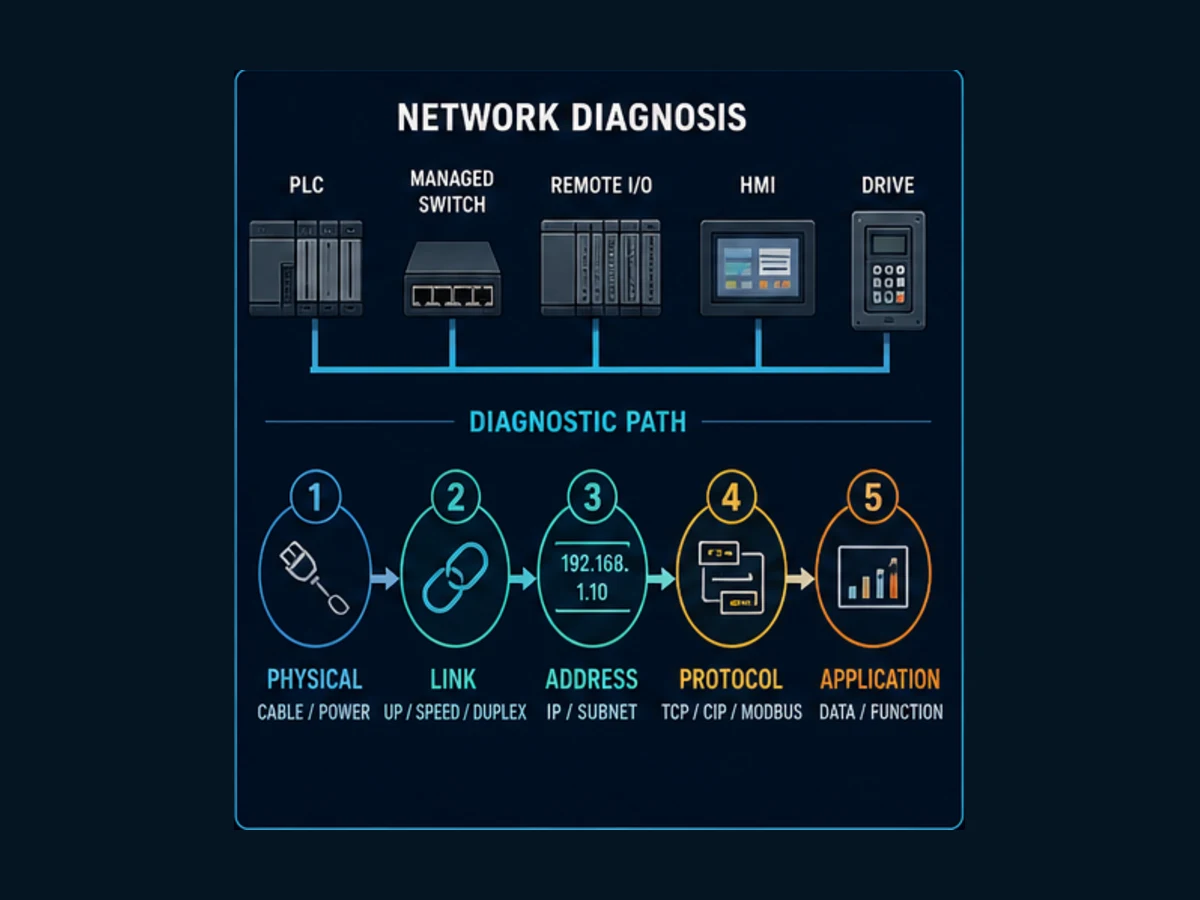
Q41. What is the difference between PROFINET and EtherNet/IP?
Model answer: Both PROFINET and EtherNet/IP are industrial Ethernet protocols that run on standard 100/1000 Mbps Ethernet hardware, but they use different upper-layer protocols and are associated with different vendor ecosystems. EtherNet/IP is maintained by ODVA and is the dominant protocol in Allen-Bradley (Rockwell) and Omron environments. It uses the CIP (Common Industrial Protocol) over TCP/IP and UDP/IP, with implicit (I/O) and explicit (messaging) connection types. PROFINET is maintained by PROFIBUS International and is the dominant protocol in Siemens environments, also used by many device manufacturers targeting European markets. PROFINET uses a layered architecture with standard TCP/IP for acyclic communication (configuration, diagnostics) and a real-time protocol (PROFINET RT) that bypasses TCP/IP for deterministic I/O communication. PROFINET IRT (Isochronous Real-Time) further supports motion control with sub-millisecond jitter. In practice, you need to use the protocol native to your PLC platform — mixing protocols requires protocol converters or gateways.
Why they ask this: Protocol selection is a real design decision. Engineers who cannot articulate this distinction have not designed systems from scratch.
Q42. What is OPC UA and why is it preferred over OPC DA?
Model answer: OPC UA is a platform-independent industrial interoperability architecture from the OPC Foundation. It defines information, message, communication and conformance models rather than only a flat tag-read service. Compared with Windows/DCOM-dependent OPC Classic deployments, UA supports richer object semantics, multiple interaction patterns and security mechanisms designed into the architecture. “Supports security” does not mean a deployment is secure by default: certificate trust, endpoint policy, identity, authorization, lifecycle and network controls still need deliberate configuration. Prefer UA when its information model, interoperability and supported profiles fit the requirement; do not claim one protocol is automatically correct for every SCADA or MES boundary. The OPC Foundation's Part 1 overview defines the architecture.
Why they ask this: OPC UA fluency is a current job market differentiator. This question appears in nearly every automation engineer interview at companies engaged in digital transformation.
Q43. How do you troubleshoot a Modbus communication failure?
Model answer: Start by confirming the physical layer: for Modbus RTU, check the RS-485 wiring — verify polarity (A/B or +/-), ensure termination resistors are installed only at the two physical ends of the bus, and check for correct cable type (twisted pair with shield). For Modbus TCP, verify network connectivity with a ping test and check switch port status. Next, confirm configuration parameters match on both master and slave: baud rate, parity, stop bits for RTU; IP address and port 502 for TCP; and critically, the slave address — every slave on a Modbus RTU bus must have a unique address, and mismatched slave addresses are the most common configuration error. Use a serial analyzer or Wireshark with a Modbus dissector to capture actual traffic — confirm the master is sending requests and observe whether responses are coming back, are malformed, or are absent. If responses are absent, suspect address mismatch, power issue on the slave, or a failed slave device. If responses are malformed, suspect baud rate or parity mismatch. If responses are valid but data looks wrong, suspect register address offset — Modbus addresses have a 0-based vs 1-based addressing ambiguity between manufacturers that trips up integrators constantly.
Why they ask this: Modbus troubleshooting is a practical skill test. The register addressing ambiguity (Modicon convention vs 0-indexed) is a specific gotcha that reveals real fieldwork experience.
Q44. What is PROFIBUS and how does it differ from PROFINET?
Model answer: PROFIBUS DP is a serial fieldbus commonly deployed over RS-485, while PROFINET is an industrial Ethernet system. They differ in physical layer, topology, device description, timing mechanisms, diagnostics and engineering workflow; they are not merely slow and fast versions of one protocol. A design may retain PROFIBUS because of the installed base, device availability or migration risk, while a new Ethernet architecture may select PROFINET when its capabilities meet the control and lifecycle requirements. Verify the specific conformance class, real-time feature, topology and device profile rather than assuming every PROFINET installation behaves identically. PROFIBUS uses GSD device descriptions; PROFINET uses GSDML. PI's current PROFINET technology overview is the primary orientation source.
Why they ask this: Both are still in active use. Knowing both, and the migration path between them, is expected for any engineer working in Siemens environments.
Q45. What is network segmentation and why is it important in industrial networks?
Model answer: Segmentation creates controlled boundaries between assets or zones with different functions, trust assumptions and communication needs. VLANs can separate broadcast domains, but a VLAN alone is not an access-control policy; routing, firewall rules, identity, monitoring and recovery design determine what can cross the boundary. In OT, define required data flows, deny unnecessary paths, protect management planes and validate that security controls do not violate safety, timing or availability requirements. Do not present a single layered drawing as universal architecture. NIST SP 800-82 Rev. 3 gives current OT-security guidance while explicitly addressing performance, reliability and safety constraints.
Why they ask this: Network design responsibility is increasingly part of the automation engineer role, especially with IIoT integration pushing more IT-OT convergence.
Q46. What is Modbus and what are its main limitations?
Model answer: Modbus defines an application-layer data model and function codes used over transports including serial line and TCP/IP. Conventional deployments expose coils and 16-bit registers with limited type and semantic information, so byte/word order, scaling, register maps and zero-versus-one-based references must be agreed outside the basic data model. Base Modbus traffic does not supply the identity and confidentiality expected at an untrusted boundary. The Modbus Organization also publishes a separate Modbus Security protocol using TLS and X.509 certificates, so “Modbus can never be secured” is too broad. State the exact variant and threat model. The official specifications page separates the application, serial, TCP and security documents.
Why they ask this: Modbus is ubiquitous and its limitations are relevant to system design decisions — particularly security and scalability.
Q47. What is the purpose of VLAN tagging in an industrial network?
Model answer: VLAN (Virtual Local Area Network) tagging allows a single physical network switch to logically segregate traffic into multiple separate networks. IEEE 802.1Q VLAN tagging inserts a 4-byte tag into Ethernet frames that identifies which VLAN the traffic belongs to. In industrial networks, VLANs are used to separate traffic by function: one VLAN for field device I/O traffic, another for SCADA and HMI traffic, another for engineering workstations, and another for remote access. This segregation improves performance (broadcast traffic from one VLAN does not flood other VLANs), improves security (devices in different VLANs cannot communicate without passing through a firewall or router, where rules are enforced), and simplifies network management. Industrial managed switches from brands like Cisco, Hirschmann, and Phoenix Contact support VLAN configuration and are rated for the temperature and vibration environments of industrial panels.
Why they ask this: VLAN design is a practical networking task in industrial environments. This tests whether your networking knowledge goes beyond the basics.
Q48. Explain the difference between a hub, a switch, and a managed switch in an industrial context.
Model answer: A hub repeats received traffic to every port and shares one collision domain. A switch learns forwarding information and sends ordinary unicast traffic toward the relevant port. An unmanaged switch offers little or no configuration; a managed switch may add VLANs, redundancy controls, port mirroring, quality-of-service features, diagnostics and management access. Select a managed switch when the design needs those controlled functions and can maintain its configuration securely. A small isolated cell may have different requirements from a redundant plant backbone. “Managed” is not automatically safer: default credentials, exposed management services, an undocumented configuration or an untested loop protocol can create new failure modes.
Why they ask this: A candidate who recommends an unmanaged switch for a large distributed control system reveals a gap in networking knowledge.
Q49. What is MQTT and why is it relevant to industrial automation?
Model answer: MQTT is a lightweight client/server publish-subscribe transport protocol. Publishers send application messages under topics to a broker; subscribers receive messages for authorized subscriptions, decoupling producers from individual consumers. MQTT does not by itself define an industrial information model, tag namespace or complete security architecture. An implementation must deliberately select authentication, authorization, encrypted transport where required, topic governance, quality of service, retained-message behavior, session handling and a payload contract. Sparkplug is one possible industrial convention layered on MQTT, not part of the base MQTT standard. The OASIS MQTT 5.0 standard is the protocol source.
Why they ask this: MQTT and IIoT knowledge is increasingly expected in automation engineer roles at companies investing in digital manufacturing. This separates candidates who have kept current with industry trends.
Q50. What is a gateway in industrial networking and when would you use one?
Model answer: A protocol gateway is a device that translates between two different communication protocols, allowing devices that would otherwise be incompatible to exchange data. Common examples include a Modbus TCP to EtherNet/IP gateway (allowing a legacy Modbus device to appear as a native EtherNet/IP device to an Allen-Bradley PLC), a PROFIBUS to PROFINET gateway (allowing legacy PROFIBUS field devices to connect to a PROFINET-based controller), or a serial to Ethernet gateway for legacy RS-232 devices. Gateways are used when replacing legacy devices is not practical — either because of cost, because the device is embedded in a machine warranty, or because the replacement cycle has not occurred yet. The tradeoff is added complexity, additional potential failure points, and sometimes latency introduced by the translation layer. When possible, replacing the device with a native protocol device is preferable to adding a gateway, but gateways are a practical reality in brownfield projects.
Why they ask this: Every automation engineer working on brownfield projects encounters gateways. Understanding when and why to use them (and their limitations) is practical knowledge.
System Design Questions
These 10 questions are predominantly asked of senior candidates and lead engineers. They assess your ability to think at the system level, make architectural decisions, and communicate design rationale.
Q51. How do you determine the I/O count for a new automation project?
Model answer: I/O counting is a systematic process that starts with the P&ID and equipment list. For each instrument on the P&ID, you identify whether it produces a discrete input, analog input, discrete output, or analog output to the control system. For each motor, you count the control outputs (start/stop command, speed reference) and feedback inputs (run status, fault, overload). Safety systems may require dedicated safety I/O separate from standard I/O. Once you have the raw count, add a spare factor — industry standard is 10–15% spare in each I/O category to accommodate late design changes and future expansion. Group I/O by physical location to determine remote I/O drop locations and panel sizing. Calculate power requirements for the I/O modules. Validate the count against the equipment list and HAZOP action items to confirm no instruments were missed. I/O counts drive hardware costs directly, so over-counting (padding) and under-counting (change orders) both have real project cost implications.
Why they ask this: I/O counting is a foundational project engineering task. Doing it wrong leads to hardware specification errors that are expensive to correct.
Q52. What is a Functional Design Specification (FDS) and what does it contain?
Model answer: A Functional Design Specification describes how a control system will behave — it is the translation from process requirements to control system design. A well-structured FDS includes: an overview of the process and control system scope; a description of operating modes (auto, manual, startup, shutdown, cleaning); a detailed description of all control loops (setpoints, ranges, failure modes); a complete I/O list with tag names, ranges, signal types, and instrument specifications; interlock and permissive logic descriptions in plain language; alarm list with priority, setpoint, and required operator response; HMI navigation structure and key screen descriptions; network architecture diagram; and safety system interface requirements. The FDS is the primary document for FAT (Factory Acceptance Test) planning — every function described in the FDS should have a corresponding test procedure. Writing a clear FDS before coding begins is the single most effective way to avoid scope creep and late-project rework.
Why they ask this: FDS authorship separates engineers who code to spec from engineers who create specs. Senior roles require both.
Q53. How would you design a control system for a water treatment facility?
Model answer: A water treatment control system is a continuous process application. Start by understanding the process stages — intake, coagulation, flocculation, sedimentation, filtration, disinfection, storage, and distribution — and identify the control loops and interlocks at each stage. Select a PLC/DCS platform appropriate for the scale: a small facility might use Allen-Bradley CompactLogix or Siemens S7-1200; a large facility warrants ControlLogix or S7-1500 with distributed I/O. SCADA is typically required for remote monitoring and long-term data logging — Ignition and WinCC are common choices in this sector. Network the system following ICS security standards (IEC 62443), with the SCADA DMZ separated from the control network. Implement redundancy at the PLC and SCADA levels for facilities where downtime affects public health. Design the alarm system to ISA-18.2 — water treatment plants are notorious for alarm flooding during process upsets. Ensure the system complies with relevant regulations (EPA, local water authority) and that all process data required for regulatory reporting is captured in the historian. Coordinate with the instrumentation engineer on chemical dosing system interlocks, which are safety-critical.
Why they ask this: Scenario design questions reveal how you think about system architecture. There is no single correct answer — interviewers evaluate your reasoning process.
Q54. What factors drive the choice of a PLC platform for a new project?
Model answer: Platform selection is a multi-factor decision. First, alignment with the end user's standard: if the plant already runs Allen-Bradley and has trained maintenance staff, selecting Siemens creates long-term support problems regardless of the technical merits. Second, the application requirements: motion control, safety I/O count, I/O count and type, scan time requirements, and communication protocol needs should all match the platform's capabilities. Third, software licensing costs: TIA Portal, Studio 5000, and CODESYS-based platforms have different licensing models that affect total project cost. Fourth, long-term support and vendor stability: avoid platforms from vendors with uncertain futures for critical infrastructure. Fifth, available skill pool: a platform that requires scarce specialists creates a maintenance risk for the end user. For greenfield projects, EtherNet/IP-based platforms dominate in North America, while PROFINET-based platforms are more common in Europe. For systems integrators, standardizing on one or two platforms deeply is more valuable than broad shallow coverage.
Why they ask this: This is a senior-level judgment question. Interviewers want to see you balance technical requirements against organizational and lifecycle considerations.
Q55. What is a Factory Acceptance Test (FAT) and how do you prepare for one?
Model answer: A Factory Acceptance Test is a structured test of a control system or machine conducted at the integrator's facility before shipment to site. The goal is to identify and resolve functional issues in a controlled environment where modifications are cheaper and faster than on site. FAT preparation starts with developing a detailed test procedure from the FDS — every function described in the spec should be tested and verified. The test environment should simulate field conditions as closely as practical: I/O simulators for field devices, actual network architecture, and real HMI hardware. The FAT agenda typically covers: hardware checkout (correct I/O wiring, module configuration), network communication tests, all normal operating sequences, all interlock and safety permissive tests, alarm tests, failure mode tests (what happens when a sensor fails, a network link drops), and SCADA/historian integration verification. Customer witness is normal — the customer's engineer and operations team observe the test. All deviations are documented on a punch list, resolved before shipment or formally accepted for on-site resolution. A clean FAT is the best indicator of a smooth commissioning.
Why they ask this: FAT execution is a project deliverable at most integration firms. This question tests whether you have been through one and understand its purpose.
Q56. How do you approach a brownfield automation upgrade project?
Model answer: Brownfield upgrades are fundamentally different from greenfield projects because the process is running — downtime is expensive and risk is high. Start with a thorough site survey: document existing control philosophy, I/O lists, interlock logic, HMI layouts, and network architecture before touching anything. Operator interviews are essential — experienced operators know undocumented interlocks and process quirks that are not in any drawing. Design the new system in parallel with the old one where possible, using migration strategies that minimize production interruption: phased cutover (cut over one section at a time), parallel operation (run new and old systems simultaneously until the new system is proven), or a full cutover during a planned outage window. Ensure all documentation is updated before the project closes — legacy projects frequently have drawings that do not match the installed system, and carrying that debt into the new installation compounds maintenance problems. Plan the cutover procedure in detail, with clear rollback steps if the new system has problems. Safety reviews are mandatory before any modification to an operating safety system.
Why they ask this: Brownfield projects are the majority of real automation engineering work. This answer reveals whether a candidate has genuine production environment experience.
Q57. What is a P&ID review and why is it a critical project step?
Model answer: A P&ID review (also called a P&ID checkmark or P&ID walkdown) is a formal engineering review that validates the P&ID against the physical installation, the control system configuration, and the process design. From an automation perspective, a P&ID review checks that every instrument shown on the P&ID has a corresponding tag in the control system, that instrument ranges match the P&ID annotation, that control loops are correctly represented (the P&ID shows controller FC-101 — does the PLC have a PID loop for FC-101 with the correct transmitter input and control valve output?), and that safety interlocks shown on the P&ID are implemented in the control logic. P&ID reviews catch omissions and discrepancies before they become site commissioning problems. They are a contractual deliverable on most engineering procurement construction (EPC) projects and are required by process safety management (PSM) regulations in certain industries. The P&ID is a living document — it must be updated to as-built status at project close.
Why they ask this: P&ID review discipline is a professional maturity indicator. Engineers who skip this step generate commissioning problems.
Q58. How do you estimate the engineering hours for a PLC programming project?
Model answer: Hours estimation for PLC programming should be broken down by deliverable, not estimated as a single number. Typical breakdowns include: I/O list development and hardware configuration (0.5–1 hour per I/O point for discrete, 1–2 hours for analog with scaling and diagnostics), control logic programming (varies enormously by complexity — a simple motor permissive is 1–2 hours, a PID loop with autotuning and cascade is 4–8 hours, a complex batch sequence per ISA-88 can be 20–40 hours), HMI development (2–4 hours per screen for standard screens, 8–16 hours for complex overview or trend screens), alarm configuration (0.5–1 hour per alarm), FAT preparation and execution (10–20% of programming hours), and commissioning support (typically estimated as a percentage of the programming budget, 25–50% for complex systems). Apply a complexity multiplier for new platform experience, integration with unusual systems, or incomplete design documentation. Always add contingency (10–20%) for scope changes — they always happen. Parametric estimation methods improve with a database of historical project actuals.
Why they ask this: Estimation capability is a senior engineer competency. Systematic estimation signals project management experience.
Q59. What is ISA-88 and when would you apply it?
Model answer: ISA-88 (S88) is the international standard for batch control systems. It defines a hierarchical physical and procedural model for batch processes. The physical model defines levels from Enterprise down through Site → Area → Process Cell → Unit → Equipment Module → Control Module. The procedural model defines Procedure → Unit Procedure → Operation → Phase as a hierarchical recipe structure. In practice, ISA-88 is applied in industries like pharmaceutical manufacturing, food and beverage, specialty chemicals, and any application where a product is made in discrete batches using equipment that handles multiple product recipes. A well-implemented ISA-88 system separates the recipe (what to do) from the equipment control (how to do it), allowing process development teams to modify recipes independently of the control system programmers. Applying ISA-88 to a simple on/off machine is over-engineering — it is appropriate for multi-step, multi-product batch processes where recipe flexibility and batch genealogy tracking are requirements.
Why they ask this: Knowing a standard's name is table stakes. Knowing when to apply it and when not to apply it demonstrates engineering judgment.
Q60. How would you design the network architecture for a large manufacturing facility?
Model answer: A large manufacturing facility network follows a hierarchical architecture aligned with the ISA-95 Purdue Model, though converged OT/IT architectures are increasingly common. Level 0–1 is the field device level — sensors, actuators, drives on fieldbuses. Level 2 is the control level — PLCs, safety systems, motion controllers communicating via EtherNet/IP or PROFINET on a dedicated control VLAN, physically separated from other traffic. Level 3 is the operations level — SCADA servers, historians, MES systems in a DMZ zone with firewall-controlled connectivity to both the control network and the business network. Level 4 is the enterprise level — ERP, business analytics, corporate IT network. Remote access should terminate in the DMZ via a jump server with MFA, never directly to the control network. Implement ring redundancy at the control network level using RSTP or a proprietary ring protocol. Plan for adequate bandwidth with margin for growth. Involve the plant's IT security team early — late-stage security requirements are expensive to retrofit.
Why they ask this: Senior automation engineers are frequently asked to contribute to or lead OT network design. This answer demonstrates the breadth of knowledge required for a lead role.
Troubleshooting Scenario Questions
These questions assess your problem-solving methodology under conditions of incomplete information — which is exactly what field troubleshooting looks like.
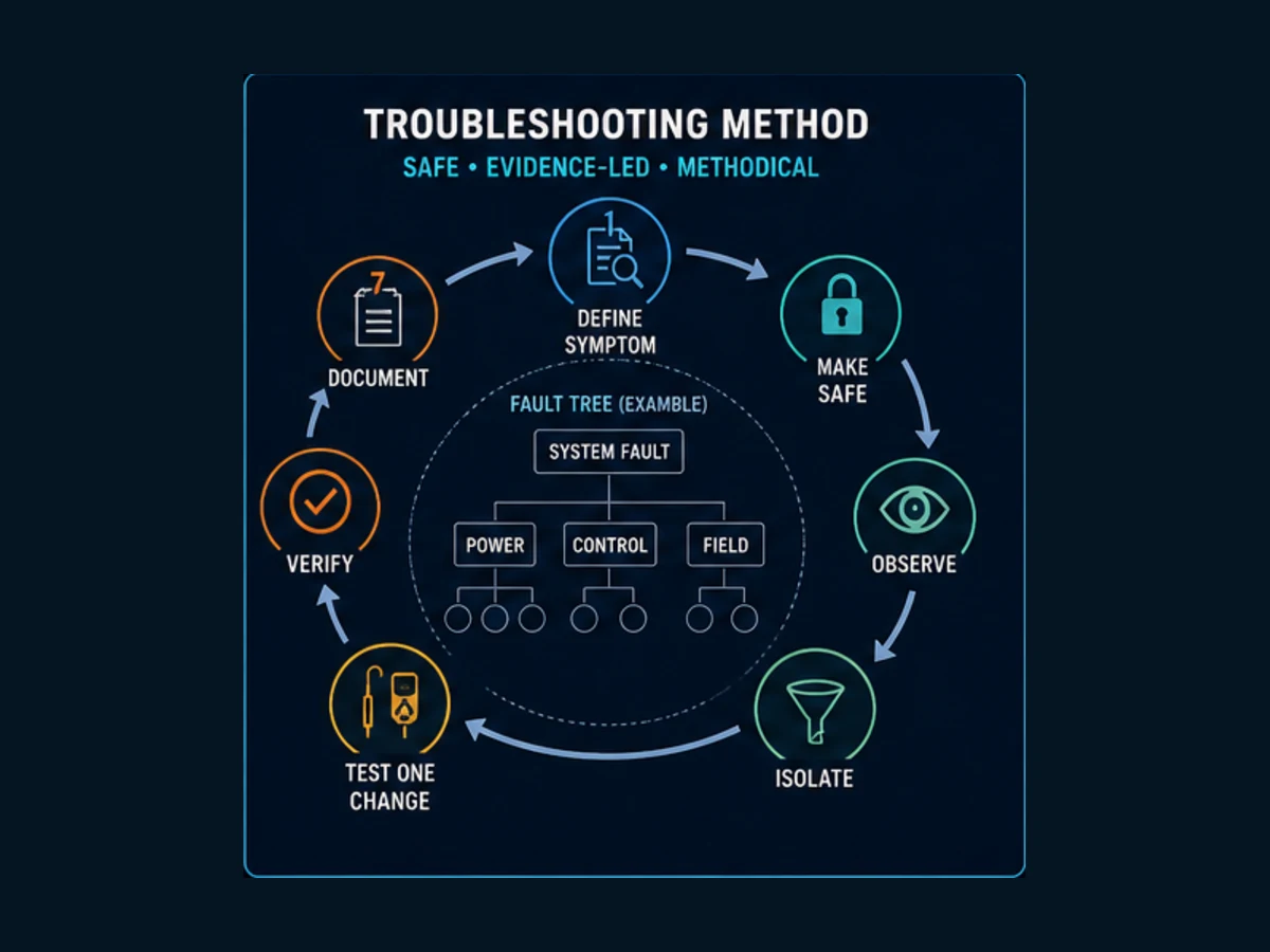
Q61. A motor will not start when the operator presses the start button. Walk me through your troubleshooting process.
Model answer: First define the symptom and safe test boundary: which motor, mode, command source and expected state, whether anyone is exposed, and which approved energy-control or live-diagnostic procedure applies. A stop command, safety function and energy isolation are different layers; never imply that an HMI stop or PLC bit makes equipment safe. Under authorized conditions, trace the signal path without forcing: operator request, PLC-visible request, mode and permissives, safety status, output command, physical output, power interface, contactor or drive state, and independent run feedback. The first point where expected and observed state disagree narrows the fault domain. If measurement or intervention is required, use the site procedure, drawings and appropriately qualified personnel. After correction, remove temporary test conditions, exercise the normal and relevant fault cases, confirm alarms and feedback, and document the restored state. OSHA's 29 CFR 1910.147 is a useful US reference for hazardous-energy control; the applicable law and site procedure may differ by jurisdiction.
Why they ask this: This is the definitive troubleshooting methodology question. The answer reveals whether you work systematically or randomly.
Q62. An analog input reads erratically. What do you check?
Model answer: Start at the signal source: confirm whether the transmitter is powered correctly — a loop-powered 4–20 mA transmitter requires typically 12–24 VDC across the loop. Check the transmitter's local indicator if it has one — does the transmitter itself show a stable reading? If the transmitter reads stable locally but the PLC reads erratically, the problem is in the signal path. Check the cable for damage, poor terminations, or routing near high-voltage conductors or variable frequency drives that can induce noise onto the signal cable — this is an extremely common cause of analog noise. Verify the cable shield is properly grounded at one end only (typically the panel end). If the cable checks out, test the signal directly at the analog input card terminals with a calibrator — does the card read the stable calibrator signal correctly? If yes, the transmitter or cable has a problem. If the card reads the calibrator erratically, the input card or its power supply may be faulty. Also check for loose terminal block connections — resistance in the loop changes the 4–20 mA signal directly. Finally, confirm the module configuration matches the signal type (4–20 mA vs 0–10 V).
Why they ask this: Analog signal troubleshooting is a practical skill test. The VFD noise culprit is a classic field scenario that separates experienced engineers from classroom-trained ones.
Q63. A communication link to a remote I/O rack goes down intermittently. How do you diagnose it?
Model answer: Intermittent communication faults are the most difficult to diagnose because they are not present during normal testing. Start by checking the switch diagnostic logs — managed switches record port statistics including error counts, CRC errors, and link state changes. If the switch shows high error rates on the port connecting to the remote rack, that indicates a cable or connector problem on that segment. Check the cable run physically — look for damage, sharp bends, cable running in cable trays with power cables (separation of 6 inches is the minimum, 12 inches is better for EtherNet/IP). Verify the connectors are properly crimped and fully seated. If the cable is clean, check the adapter in the remote rack — review the adapter's diagnostic web page if it has one, or the SCADA trend of the communication fault tag to identify the time pattern. If faults follow a pattern (always in the morning, always when a nearby VFD starts), the problem is environmental — VFD EMI, temperature cycling causing a connection to intermittently open, or power supply voltage dip on VFD startup. Use a network tester to perform a full cable certification and check for impedance discontinuities. If no physical cause is found, check the RPI setting — if the requested packet interval is set aggressively relative to network load, timeouts will occur under load conditions.
Why they ask this: Intermittent faults require patience, methodology, and knowledge of the failure modes. This is a senior-level troubleshooting scenario.
Q64. A PID loop is hunting continuously. What are the likely causes and how do you tune it?
Model answer: Continuous oscillation (hunting) in a PID loop usually indicates one of three root causes: excessive proportional gain, excessive integral gain causing windup, or a process dead time that is long relative to the loop's response time. Start by putting the loop in manual and observing the process — is the process variable stable in manual? If not, the problem may be a mechanical issue (sticky valve, oscillating disturbance) rather than tuning. If stable in manual, perform a step test: apply a small step change to the output and record the process variable response. From the step test, calculate the process gain, dead time, and time constant. Use the Ziegler-Nichols or Lambda tuning method to calculate initial P, I, and D settings. In most process control applications, reducing integral gain (increasing integral time in minutes/repeat units) resolves hunting. Derivative action should be zero to start — only add derivative if the P-I tuned loop has unacceptable overshoot. For loops with significant dead time relative to time constant, consider a dead time compensator (Smith Predictor) rather than trying to tune around the limitation.
Why they ask this: PID tuning methodology is a practical controls engineering skill. The answer reveals whether you approach it systematically or by trial and error.
Q65. Describe how you would commission a new PLC panel from scratch.
Model answer: Commissioning a new PLC panel follows a defined sequence. Before energizing anything: verify wiring against the panel drawings (point-to-point continuity check on all I/O, power wiring, and grounding), confirm correct fusing for every circuit, verify proper DIN-rail grounding and panel bonding. First power-up: measure DC supply voltages, verify PLC power LED status, connect with programming software and confirm hardware configuration matches the physical modules. I/O checkout: with the process isolated and personnel clear of all actuators, test every discrete output (force the output bit and verify the terminal voltage, then physically verify the actuator response), test every discrete input (activate each sensor or switch and verify the bit in the PLC), and test every analog I/O point (inject calibrated signals on analog inputs, apply analog output signals and measure the terminal output). Logic testing: run through all normal operating sequences, test each interlock by simulating the interlock condition, and verify that all alarm conditions set the correct alarms. Communication testing: verify all remote I/O, SCADA, and third-party device communications. Document every step with actual measured values and any deviations from design. This process typically runs 20–50% longer than planned — budget accordingly.
Why they ask this: Commissioning methodology is a practical engineering skill that reveals experience and professional discipline.
Q66. A VFD is tripping on an overcurrent fault intermittently. How do you troubleshoot it?
Model answer: VFD overcurrent faults indicate that the drive's output current exceeded the drive's rated limit or its user-configured overcurrent threshold. Start by reviewing the drive's fault log for the exact fault type and the operating conditions (speed, load, elapsed time) at the time of the fault. Common causes include: mechanical overload (the load on the motor increased — check for bearing wear, mechanical binding, increased product weight or density on a conveyor), incorrect drive parameter settings (acceleration rate too fast, current limit too low relative to the application's actual peak demand), motor cable insulation failure causing partial short to ground at elevated temperatures, or a deteriorating motor winding creating unbalanced phase currents. If the fault is reproducible, trend the drive's output current (most drives have built-in monitoring) to capture the current profile just before the fault. If the current exceeds rated motor current on a properly loaded machine, check the mechanical system first. If the current is within normal range and the fault appears to be false, suspect a drive fault parameter threshold set below the application's normal peak current demand.
Why they ask this: VFD troubleshooting is a common real-world task. The ability to use the drive's own diagnostic data demonstrates practical fieldwork.
Q67. You have a machine that runs correctly for 30 minutes, then faults with a "program scan overrun" error. What do you investigate?
Model answer: A scan overrun means the program is taking longer to execute than the configured watchdog timeout or task period. Occurring after 30 minutes suggests a condition that develops over time rather than an immediate fault. The most common causes of time-dependent scan overruns are: a memory leak or accumulating data structure (an array or buffer filling up and making searches slower), a communication task that blocks the scan under certain conditions, a growing message queue from MSG instructions, or a task that takes increasingly long to execute as production data accumulates. Go online during normal operation and monitor the task scan time using the Controller Diagnostics. If possible, capture the scan time trend over 30 minutes and observe whether it increases steadily or jumps at a specific event. Look for MSG instructions in the program that do not have proper response handling — MSG instructions waiting for responses that never come will hold their task slot open, consuming scan time. Check for any FOR/WHILE loops in Structured Text that could execute more iterations as a table fills. Verify the task's watchdog setting against the actual scan time — if the application genuinely needs more time, increasing the watchdog is a valid fix once the root cause is understood.
Why they ask this: Time-dependent faults require diagnostic thinking that goes beyond looking at the current system state — they require understanding dynamics. This is a mid-to-senior level question.
Q68. An HMI screen shows incorrect values for a sensor that the PLC is displaying correctly. How do you diagnose it?
Model answer: The discrepancy between PLC and HMI values points to a data transmission issue or a tag configuration mismatch. First, confirm which value is actually correct — connect with PLC programming software and read the tag value directly. If the PLC value matches the real-world reading, the HMI is the problem. Check the HMI tag database: verify the HMI tag is mapped to the correct PLC tag name or register address. Scaling discrepancies are common — the HMI may be applying a different scale factor than the PLC, or may be reading a raw count rather than the already-scaled engineering value. If the tag mapping is correct, check for a communication stale data condition — some SCADA systems will freeze at the last known value if the connection is intermittent, while others show an alarm indicator. Check the communication connection status in the SCADA platform and review the communication error log. If the tag mapping and communication both look correct, check whether the SCADA software is showing a cached or delayed value — compare the SCADA timestamp of the displayed value against the PLC clock to detect an update rate issue.
Why they ask this: PLC-to-HMI data discrepancy is a common commissioning issue. This reveals whether you know how to isolate the problem layer by layer.
Q69. You arrive on site for a planned maintenance window and the PLC is in fault. Describe your approach.
Model answer: A PLC in fault mode means the processor has stopped executing the user program. Start by checking the processor status: view the fault type using the programming software. In Allen-Bradley, connect with RSLinx and read the Major and Minor fault codes in the Controller Properties. In Siemens, go to the Online and Diagnostics view. The fault code will tell you whether this is a hardware fault (module failure, power supply issue), a software fault (program error, watchdog timeout, illegal instruction), or a communication fault (lost connection to a required device). For a software fault, read the exact fault address and routine to locate the fault in the program. For a hardware fault, identify the faulted module (fault LED on the module, diagnostics in software) and inspect it physically. Once you understand the cause, do not simply clear the fault and restart without understanding why it occurred — faults are information. Document the fault code, time, and circumstances in the maintenance log. For a planned maintenance window, if the fault predates your arrival, check the control system event log to determine when the fault occurred and what preceded it.
Why they ask this: Responding to a faulted PLC is a real professional scenario. The instruction to not clear-and-restart without understanding reveals engineering discipline.
Q70. A safety relay circuit is not allowing the machine to reset. Walk through your diagnostic approach.
Model answer: Safety relay diagnostics must be approached carefully — never bypass or jumper safety circuits during troubleshooting without following your site's lockout/tagout procedure and getting explicit engineering authorization. Start by reviewing the safety circuit schematic. Safety relays require specific reset sequences: typically, all safety inputs must be in their safe state (E-stops released, guards closed, light curtains unobstructed), then a manual reset button must be pressed and released within a specified pulse width — a press-and-hold or instantaneous pulse that does not meet the reset timing requirements will not latch the relay. Identify the safety relay's diagnostic LED indicators — most modern safety relays (Pilz, SICK, Rockwell) have multi-color LEDs or status codes that indicate exactly which condition is preventing reset: input fault, cross-fault between channels, external device monitoring (EDM) fault from the contactor feedback, or internal relay fault. Check the EDM (External Device Monitoring) circuit — if the safety relay monitors contactor feedback and the contactor contacts are worn or sticky, the EDM circuit will prevent reset. Only after methodically confirming all input conditions and following the reset sequence should you suspect the safety relay itself.
Why they ask this: Safety system troubleshooting requires specific knowledge and professional discipline. The emphasis on not bypassing safety circuits is the answer hiring managers specifically listen for.
Behavioral and Soft Skills Questions
These five questions are typically asked in the final interview round. Your answers should be specific and honest — generic answers are obvious and unconvincing.
Q71. Tell me about a commissioning that went wrong and what you learned from it.
Model answer (structure): Choose a real story where something genuinely went wrong — not a minor hiccup. The STAR format works well here: describe the Situation briefly, explain the Task or problem clearly, describe the Action you took (including mistakes made and corrections), and articulate the Result and specifically what you learned. The most compelling answers acknowledge what you did wrong or what you should have caught earlier. What interviewers want to hear is that you understand the root cause, that you took ownership, and that you changed your practice as a result. An example structure: "We had a VFD commissioning where we had not confirmed the motor nameplate parameters before the FAT, and the drives were configured with the wrong rated current — we discovered this during field commissioning when the drives were tripping on overload at 60% of rated load. The lesson I took from that was to make FLA verification a mandatory checklist item before any FAT, not something I leave to the panel builder." Avoid stories where everything that went wrong was someone else's fault.
Why they ask this: Self-awareness and the ability to learn from failure predict how well someone will develop professionally. Candidates who cannot recall a commissioning failure are either inexperienced or defensive.
Q72. How do you handle scope creep on an automation project?
Model answer: Scope creep is managed by making it visible and explicit as early as possible. When a new request comes in during a project — a customer asks for an additional alarm, an additional HMI screen, or a change to the interlock logic — the first step is to evaluate the impact on schedule, cost, and engineering effort. Small changes (under 2 hours of engineering) can often be absorbed in the existing budget with good documentation. Larger changes require a formal change order with a written scope description, hours estimate, and cost to the customer or internal project manager. What you should avoid is the "yes, no problem" response that results in uncompensated overtime and scope that did not make it into the final documentation. Maintain a running change log on every project — it protects both parties. In customer-facing contexts, framing scope changes as "let me check if this can fit within the current scope" rather than an immediate yes or no is more professional and gives you time to assess impact before committing.
Why they ask this: Scope management is a professional skill that distinguishes engineers who succeed on project-based work from those who do not.
Q73. Describe a time you identified and fixed a safety issue in an existing control system.
Model answer (structure): Describe a real scenario where you identified a genuine safety gap — an improperly configured E-stop, an alarm that was suppressed but never investigated, a guard bypass that had become permanent, a PLC program modification that removed a critical interlock. Explain how you identified it (audit, incident investigation, casual observation), how you assessed the risk (consulted standards, involved a safety engineer, used a risk matrix), and what you did about it (formal change management, temporary risk mitigation while the permanent fix was designed, retraining). The critical element is that you followed a process — you did not just fix it yourself without documentation, and you involved appropriate stakeholders. What makes this answer stand out is demonstrating that you proactively look for safety issues rather than waiting for incidents to reveal them.
Why they ask this: Safety culture is non-negotiable in industrial environments. This question screens for candidates who treat safety as a personal professional responsibility.
Q74. How do you approach learning a new PLC platform you have never used before?
Model answer: Start with the manufacturer's official documentation and training — most platforms have free online courses (Rockwell has PLC Programming with Logix 5000, Siemens has the SITRAIN Academy, Beckhoff has InfoSys). Download the programming software and work through a structured exercise — program a simple machine sequence that uses timers, counters, analog I/O, and communication — in the simulator before touching any real hardware. Study the differences from platforms you already know: the fundamental programming concepts are the same across all IEC 61131-3 compliant platforms; what differs is the tooling, the instruction set names, the data type conventions, and the hardware configuration workflow. Use the software's built-in help system — it is more accurate than forum posts for platform-specific details. When possible, find a colleague or mentor who knows the platform and buy them lunch in exchange for a few hours of hands-on orientation. Accept that the first real project on a new platform will take longer than it would on a familiar platform, and account for that in your schedule estimate.
Why they ask this: Technology changes constantly in automation. Interviewers want to hire people who will learn new tools independently without requiring hand-holding.
Q75. How do you ensure your PLC programs are maintainable for the next engineer?
Model answer: Maintainability is a professional obligation, not optional. The practices I apply consistently are: meaningful tag names that encode the function and device location without requiring a lookup (e.g., Conv1_MotorRun_Cmd rather than B3:0/5), rung comments that explain the intent of the logic rather than restating what the code already shows (the comment "seal-in contact holding motor output energized" adds nothing; "motor remains running until operator presses stop or overload trips" explains the intent), consistent program organization that matches the machine's physical and functional structure so that a maintenance technician can navigate to the section they need, and an I/O cross-reference document that maps every physical terminal to its tag name and function. For complex logic, I include block comments explaining the overall algorithm before the detailed rungs. I also follow my organization's programming standards document — if one does not exist, I advocate for creating one. The test I apply is: if I were handed this program at 2 AM during a production emergency with no other documentation, could I understand it well enough to troubleshoot it in 30 minutes?
Why they ask this: Maintainability directly affects the lifetime cost of a control system. This question tests professional maturity and team-mindedness.
Questions You Should Ask the Interviewer
Asking intelligent questions at the end of an interview is not a formality — it signals preparation and genuine interest, and gives you information you actually need. Avoid questions whose answers are on the company's website.
1. "What does the first 90 days look like for this role — what would I be working on, and what does success look like?" This shows you are thinking about contribution, not just compensation, and gives you concrete information about whether the role matches your skills.
2. "What is the biggest technical challenge the team is facing right now?" This immediately puts you in a collaborative frame and reveals what you will actually be dealing with on day one. It also gives you an opportunity to respond with relevant experience.
3. "How is the engineering team structured, and how does the automation team interface with mechanical, electrical, and process engineering?" Collaboration structure affects your daily work life enormously. Teams that are poorly integrated frustrate engineers who want to do good work.
4. "What PLC platforms and SCADA software does the team primarily use, and is there a push to standardize or expand the platform mix?" Practical and relevant. This tells you what you will be learning and what your current knowledge is worth immediately.
5. "How does the company approach professional development — training budget, conference attendance, certification support?" Signals that you take your professional development seriously. Avoids the impression that you are asking only about salary.
6. "How does the team handle documentation and knowledge transfer when engineers change roles or leave?" This question reveals a great deal about the organization's engineering maturity. Teams with no answer to this question carry significant technical debt.
7. "What is the typical ratio of project work to ongoing support for this position?" The balance between new project work and maintaining existing systems is a major quality-of-life factor that is rarely stated in job descriptions.
Interview Preparation Checklist
Use this checklist in the weeks before your interview. Check off each item honestly — do not mark something done if you cannot yet explain it.
Entry-Level Candidates (0–3 Years Experience)
Technical fundamentals
- Explain the PLC scan cycle from memory, including the image table concept
- Name all five IEC 61131-3 languages and give a use case for each
- Explain TON vs TOF with a practical application for each
- Describe what a 4–20 mA signal represents and why 4 mA is the live zero
- Explain NO vs NC contacts and apply the fail-safe principle to E-stop design
- Describe a basic motor start/stop seal-in circuit in ladder logic
Software practice
- Download RSLogix Micro Starter Lite or a free PLC simulator and program: motor start/stop with seal-in, a TON timer sequence, and a simple counter application
- Practice until you can do these without reference material
Research
- Study the target company's products and customers
- Know which PLC platform they use most (LinkedIn, job description, company website)
- Prepare three specific technical examples from your academic or internship work
Salary
- Research compensation ranges for your target role and location — see the automation engineer salary guide for current data
Mid-Level Candidates (3–8 Years Experience)
Technical depth
- All entry-level items, plus:
- Explain AOIs vs subroutines (AB) or FBs vs FCs (Siemens) with architectural rationale
- Describe your analog scaling formula and the raw count range sources for your target platform
- Explain indirect addressing with a real use case
- Describe EtherNet/IP implicit vs explicit connections
- Explain OPC UA and how it differs from OPC DA
- Describe ISA-18.2 alarm management principles
Platform-specific preparation
- If targeting Allen-Bradley: review Studio 5000 AOI creation, task/program/routine hierarchy, and MSG instruction configuration
- If targeting Siemens: review TIA Portal FB/FC distinction, OPC UA server configuration, and GSDML device integration
- Review the platform comparison article on Siemens vs Allen-Bradley to anticipate comparison questions
Portfolio
- Document two or three projects with: scope, your specific contribution, challenges you overcame, and measurable outcomes
- Prepare to describe your troubleshooting methodology using a real example
Senior Candidates (8+ Years Experience)
All mid-level items, plus:
System design
- Prepare a narrative of a complete project you led from design through commissioning
- Be ready to describe your I/O counting process, FDS structure, and FAT preparation approach
- Prepare an opinion on platform selection — what factors drive the decision, what are you agnostic about
- Know IEC 62443 network segmentation principles at a conceptual level
Leadership and judgment
- Prepare two examples of scope management decisions you made under customer pressure
- Prepare a real example of a safety issue you identified and how you resolved it through proper channels
- Know ISA-88 at a conceptual level if targeting process industries
- Prepare your opinion on PLC programming standards — what standards you apply and why
Certifications
- Review the automation engineer career guide for certifications that employers in your target sector value most
Technical Sources and Edition Boundaries
This guide uses standards and vendor material to bound technical claims; it does not reproduce certification items or employer question banks. A standard tells you the shared model, while the target controller manual, module configuration, risk assessment and site procedure determine the executable detail. Check the edition and jurisdiction before turning an interview answer into field work.
| Primary source | What it supports here | Boundary to state in an interview |
|---|---|---|
| IEC 61131-3:2025 | current PLC-language suite and SFC structuring elements | older projects and courses may follow the withdrawn 2013 edition |
| Siemens S7-1200/1500 programming guideline | OB, FC, FB and instance-DB design concepts | exact features depend on CPU, firmware and TIA Portal version |
| OPC UA Part 1 | information, message, communication and conformance models | supported profiles and security configuration vary by product |
| ODVA EtherNet/IP overview | CIP over Ethernet and the EtherNet/IP technology family | topology, connection timing and device support are design inputs |
| PI PROFINET technology | current PROFINET capabilities and ecosystem | conformance class, real-time feature and device profile must be named |
| Modbus specifications | application protocol, serial/TCP guidance and separate Security protocol | register meaning and many data-type conventions remain device-specific |
| OASIS MQTT 5.0 | brokered publish/subscribe behavior and protocol controls | payload semantics and deployment security are architecture choices |
| ISA-18 series | alarm-management lifecycle and supporting reports | site alarm philosophy and rationalization records govern implementation |
| NIST SP 800-82 Rev. 3 | OT-security architecture and controls with safety and availability constraints | cybersecurity changes still require site risk and change control |
| OSHA 29 CFR 1910.147 | US general-industry hazardous-energy-control baseline | other jurisdictions and site procedures may impose different duties |
For a model answer, cite the principle and the boundary rather than reciting clause numbers from memory. “IEC 61131-3:2025 defines ST, LD and FBD, with SFC structuring elements; I would confirm what this project and toolchain implement” is more reliable than an unqualified list learned from an older slide deck.
Frequently Asked Questions
What technical skills do automation engineer interviews focus on most?
The recurring skill groups are PLC execution and program organization, I/O and instrumentation, control behavior, HMI/SCADA, industrial communications, safe troubleshooting and project evidence. A machine-builder role may weight motion, safety and commissioning; a process role may weight P&IDs, loops and alarm management; an OT role may weight data quality, identity and segmentation. Derive priorities from the vacancy, employer platform and interview stage.
Should I study Siemens or Allen-Bradley for my interview?
Study the platform the company uses — check their job description, LinkedIn posts, and if possible the engineering team's profiles. If unclear, ask the recruiter before the technical round. If the company uses both, focus on the one listed first. If you genuinely do not know, Allen-Bradley is the larger installed base in North America and a slightly safer bet for North American companies, while Siemens is dominant in Europe and in many automotive applications. Read the Siemens vs Allen-Bradley comparison for a detailed breakdown.
How important is networking knowledge for automation engineer interviews?
Networking depth should match the system boundary you will own. A PLC programmer should trace link, address, connection and application state. An integration or OT role should additionally discuss managed infrastructure, time behavior, redundancy, segmentation, identity, monitoring and recovery. Be able to explain EtherNet/IP versus PROFINET without turning vendor association into the technical distinction, and explain why a successful ping does not prove healthy I/O or application data.
Do I need to know Python for automation engineer roles?
Python is increasingly valued, particularly for roles that involve data analysis, IIoT integration, or working alongside IT teams. It is not a hard requirement for most traditional automation engineer roles, but it is a differentiator. If you have Python skills, mention them — particularly for tasks like parsing historian data, scripting device configuration workflows, or building simple data transformation tools. The Python vs Ladder Logic comparison article covers this intersection in more depth.
What salary should I ask for as an entry-level automation engineer?
Do not use a universal entry-level number. Compensation changes with location, industry, travel, overtime treatment, shift support, education, security clearance and the boundary between technician, programmer and engineer work. Use the employer's published range where available, then compare current government occupational data and a consistent set of local postings. The automation engineer salary guide explains the comparison method. Ask whether the quoted package includes travel pay, callouts, bonus, retirement and paid training before comparing base salary alone.
How do I prepare for a practical PLC programming test?
Practise a small sequence, mode handling, timer behavior, counter or batching logic, analog scaling and one injected fault in a simulator or isolated training environment. Know how to navigate cross-references, online state, diagnostics and traces on the target platform. Do not assume forcing is part of the test: ask about the environment and authorization, identify any active force or override, and restore the approved state when finished. Explain expected versus observed results rather than optimizing only for speed. The PLC Programming Code Pack includes timed programming exercises designed for this scenario.
What is the difference between a controls engineer and an automation engineer interview?
The titles are often used interchangeably, but there are nuanced differences in emphasis. A controls engineer role typically emphasizes control system theory (PID, process dynamics, loop tuning), safety systems (SIL, functional safety), and instrument and control design. An automation engineer role typically emphasizes machine control programming, system integration, and commissioning. In practice, the interview questions overlap significantly — both roles test PLC programming, networking, SCADA, and troubleshooting. Read the job description carefully: requirements around P&ID reading, loop tuning, and SIL knowledge suggest a controls-heavy role; requirements around Studio 5000 or TIA Portal proficiency and machine commissioning suggest an automation-heavy role.
Should I bring anything to my automation engineer interview?
Bring printed copies of your resume (enough for all interviewers), a portfolio of project examples if you have them (P&IDs you worked on, screenshots of HMI screens you designed, photos of panels you wired or commissioned — redacted for confidentiality), and a notepad for taking notes during the interview. Arriving with project documentation demonstrates professional maturity. If you completed any relevant certifications, bring a copy. If the company uses a specific platform and you have certification in it, having the certificate physically present is a subtle but effective signal.
How do industrial automation interview questions change by PLC brand?
The control principles remain similar, but the evidence vocabulary changes. A Siemens role may probe OB/FB/FC/DB organization, process images and TIA Portal diagnostics; a Rockwell role may probe tasks, programs, routines, AOIs, produced/consumed data and Logix diagnostics; an Omron or CODESYS role has its own execution, instance and tooling terms. Do not translate instruction names mechanically. State the vendor-neutral behavior first, then describe how the target platform implements it and which version-specific manual would confirm the detail.
What if I have simulation experience but little industrial hardware experience?
Describe the simulation honestly and make its boundary an engineering strength. Show the requirement, I/O contract, expected scan behavior, normal and negative tests, observed trace and what the model could not prove—electrical noise, field timing, module configuration, network loading, safety validation or mechanical behavior. Then explain the controlled commissioning steps you would use with qualified supervision. A bounded, reproducible project is stronger than implying site experience you do not have.
What to Do Next
Preparation cannot guarantee an offer, but it makes your evidence easier to evaluate. Practise the direct answer, the important boundary and one concrete example. For a troubleshooting prompt, narrate the first observation that separates competing causes rather than listing every component you might replace.
Practice out loud. Answer these questions verbally, not just in your head. Time yourself. The answers that come out of your mouth in an interview are not the same as the ones that feel clear in your mind — verbal practice is the only way to close that gap.
For additional preparation resources:
- PLC Programmer Salary Guide — compensation data for negotiation
- Automation Engineer Salary Guide — full compensation breakdown by level and location
- PLC Programming Career Development Guide — career path planning for automation professionals
- Best PLC Programming Software 2026 — platform comparison to help you focus your practice
- PLC Programming Code Pack — 200+ practice problems, annotated examples, and mock technical scenarios
Your interview is not a test of what you have memorized. It is a demonstration of how you think. Prepare accordingly.


