Control Narrative Template: How to Write PLC Logic Requirements
Write a control narrative that defines modes, permissives, sequences, failures, alarms and recovery clearly enough to program and test. Includes a worked pump example and free template.
A control narrative is a plain-language, testable description of how a machine or process must operate. It defines the equipment boundary, modes, commands, permissives, interlocks, sequence states, alarms, failure responses and recovery rules before those requirements are translated into PLC, HMI or SCADA code.
A strong narrative answers three questions for every important behavior:
- What condition causes it?
- What exactly must the control system do?
- What evidence will prove that it works?
Download the free control narrative template (CSV) or get it with the complete PLC commissioning toolkit.
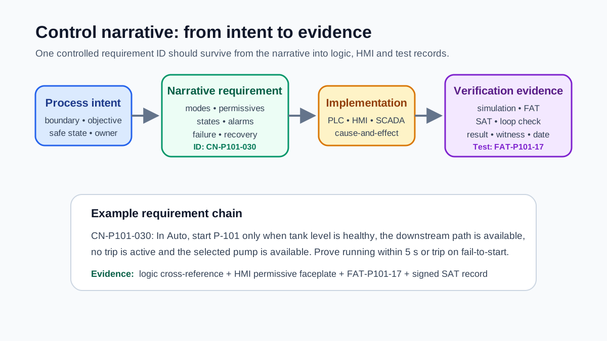
What belongs in a control narrative?
| Section | The question it must answer | Weak wording to avoid |
|---|---|---|
| Scope | What equipment, process and interfaces are covered? | “The whole system” |
| Objectives | What outcome must the controls maintain? | “Operate correctly” |
| Safe state | What state is required after each defined failure? | “Shut down safely” |
| Modes | Who may command equipment in Off, Manual and Auto? | “Manual overrides Auto” |
| Permissives | What must be true before a start or transition? | “All permissives healthy” |
| Interlocks/trips | What stops operation and whether it latches? | “Stop on fault” |
| Sequence | What are the states, entry actions and transitions? | “Run the sequence” |
| Alarms | What condition, delay, priority and response apply? | “Generate an alarm” |
| Failure response | What happens on sensor, network, power or actuator failure? | “Fail safe” |
| Recovery | Who may reset, what must be healthy and where does the sequence resume? | “Reset when clear” |
| Interfaces | What commands, statuses, handshakes and validity signals cross systems? | “Communicate with SCADA” |
| Verification | Which FAT or SAT test proves each requirement? | “Test during commissioning” |
The narrative should state functional intent without burying it in platform syntax. The programmer may implement a state in Structured Text, ladder logic or a function block, but reviewers should be able to agree on the required behavior before choosing instructions.
Control narrative versus related documents
These documents overlap, but they are not substitutes.
| Document | Primary purpose | Typical level |
|---|---|---|
| Control philosophy | Defines plant-wide principles, responsibilities and operating strategy | site or process area |
| User requirements specification | Captures what the owner needs the delivered system to achieve | project |
| Functional design specification | Converts requirements into detailed control-system functions and architecture | system |
| Control narrative | Explains equipment behavior in readable, testable operating language | unit, package or sequence |
| Cause-and-effect matrix | Shows discrete initiating causes and required effects compactly | trip, shutdown and safeguarding logic |
| I/O list | Controls the signal register, ranges, addresses and wiring ownership | every physical/software point |
| FAT/SAT protocol | Defines how approved behavior will be demonstrated and recorded | verification |
For a small machine, the narrative may be a section of the FDS. For a large process plant, there may be one narrative per unit operation. The contract between documents matters more than the filename: define one controlled owner for each requirement and use stable IDs.
See the control philosophy guide, functional design specification guide, cause-and-effect matrix and I/O list builder.
Live mini-lab
Try it: press START, then STOP
A stop-dominant seal-in rung: START latches the motor output through its own contact, and STOP breaks the circuit.
Watch the output lamp: it stays on after START until you press STOP.
Free to start · runs in your browserOpens plcsimulationsoftware.com — same team
A practical control narrative structure
1. Document control and boundary
Record the project, system, unit, document number, revision, author, reviewers and approval state. Name the equipment included and excluded. List upstream and downstream interfaces.
An unambiguous boundary might say:
This narrative covers transfer pumps P-101A/B from suction isolation status through the common discharge header, including motor commands, run feedback, tank-level permissives and HMI operation. MCC protection logic and the downstream filling sequence are interface systems.
That sentence prevents two teams from assuming the other owns the same shutdown.
2. Process purpose and assumptions
Explain what the equipment accomplishes, normal operating range, critical constraints and the source documents used. Identify unresolved assumptions as open items; do not quietly turn them into code.
Useful sources include the P&ID, equipment data sheets, package documents, HAZOP/LOPA actions, alarm philosophy, electrical single-line diagram and operating procedures.
3. Defined states and modes
Do not use mode names without defining authority.
| Mode | Typical command source | Automatic transitions? | Protections remain active? |
|---|---|---|---|
| Off/Out of service | authorized operator or maintenance state | no | defined hardwired and software protections |
| Manual | local HMI or field station | usually limited | yes, except explicitly controlled bypasses |
| Auto | sequence or process controller | yes | yes |
| Maintenance/Test | authorized temporary workflow | tightly controlled | risk-assessed, indicated and logged |
State whether mode transfer is bumpless, whether a running device may change modes, how local/remote selection works and which commands have priority. Never assume “Manual” means interlocks disappear.
4. Commands, permissives, interlocks and trips
Use these terms consistently:
- Command: a request to start, stop, open, close or change a setpoint.
- Permissive: a condition that must be true before an action begins.
- Interlock: logic that prevents or changes an action when a defined condition exists.
- Trip: a protective action that drives equipment to a defined state, often latched until reset conditions are met.
- Status/proof: evidence that the field equipment actually reached the expected condition.
For every condition, record tag/source, Boolean sense, time delay, latching behavior, bypass authority, operator indication and reset rule.
“Low level stops pump” is incomplete. A testable statement is:
CN-P101-041: If LSL-101 remains active for 2.0 seconds while either transfer pump is running, stop both pumps, latch TRIP-P101-LOW-LEVEL, inhibit restart and present the operator action “Verify source tank level and suction isolation.” Reset is permitted only when LSL-101 is clear and both run commands are off.
5. Sequence states and transitions
Write sequences as explicit states, not a paragraph full of “then.”
For each state define:
- entry condition;
- entry actions;
- commands maintained during the state;
- completion evidence;
- maximum time;
- next valid states;
- abnormal exit;
- restart behavior after a controller or power interruption.
State IDs should be stable even if display text changes. A useful state table becomes a direct starting point for code and a direct source for FAT cases.
6. Analog control
For process loops, define:
- process variable, engineering range and units;
- controlled variable and manipulated variable;
- normal setpoint source and limits;
- Auto/Manual/cascade selection;
- output tracking and bumpless transfer;
- controller direction;
- output limits and anti-windup;
- bad-quality and out-of-range response;
- fallback output, if one is justified;
- operator permissions and tuning ownership.
Avoid prescribing tuning constants in the narrative unless they are verified design requirements. Commissioned parameters belong in a controlled setting record.
7. Alarms and operator response
An alarm is not complete without an expected human response. State:
- exact initiating condition;
- on-delay and off-delay/deadband;
- priority according to the project alarm philosophy;
- latching/acknowledgement behavior;
- shelving or suppression rules;
- display text;
- operator response;
- related trip or permissive;
- historian/event requirement.
Do not create a separate alarm for every intermediate Boolean. Alarm only conditions that require timely operator awareness or action, while leaving diagnostic states available on detail displays.
8. Failure and degraded-mode behavior
Address at least:
- loss and restoration of power;
- controller restart;
- communication timeout or stale data;
- input bad quality, open circuit or out of range;
- output/module fault;
- actuator fail-to-move;
- loss of instrument air or utility;
- HMI/SCADA unavailable;
- redundant device switchover;
- sequence interruption mid-state.
“Fail safe” is not a complete requirement because the safest state depends on the hazard and process. State the demanded state and its approved basis.
9. Reset and recovery
Recovery deserves its own section. Define whether a trip is latched, who can reset it, where reset is accepted, which conditions must be healthy and whether the process returns to Idle, resumes a state or requires a new start.
Automatic restart after power restoration should never be implied. State it explicitly and align it with the machinery/process risk assessment.
Worked example: duty/standby transfer pumps
Scope and objective
P-101A and P-101B transfer liquid from TK-101 to a downstream header. One pump normally runs; the other is available as standby. The system maintains header pressure while preventing dry running and proving discharge.
Modes
- Off: no automatic start is permitted; active protective trips may still stop a manually energized output through the defined architecture.
- Manual: an authorized operator selects one pump and issues Start/Stop from the HMI. Suction-level and motor-protection trips remain effective.
- Auto: the sequence selects the available duty pump, starts on low header pressure and stops after pressure recovery plus a minimum run time.
Permissives
A selected pump may start only if:
- no active latched trip exists;
- the motor protection circuit is healthy;
- local/remote status permits remote operation;
- source-tank low-low level is clear;
- the relevant suction and discharge paths are confirmed available where feedback exists;
- the pump is not already commanded by another control owner.
Start and run proof
- Issue the run command.
- Start a 5-second proof timer.
- Confirm motor run feedback before the timer expires.
- If proof arrives, enter Running.
- If proof does not arrive, remove the command, latch fail-to-start, mark that pump unavailable and—only if the approved process strategy permits—attempt the standby pump once.
Stop and failure
Normal stop removes the run command and verifies feedback clears. Low-low tank level trips the running pump. Loss of header-pressure signal sets bad quality, disables pressure-based automatic starting and leaves the system in a defined operator-controlled state; it does not silently treat the bad value as zero.
Recovery
Reset is accepted only when the initiating trip is clear, both pump commands are off and an authorized operator presses Reset. The sequence returns to Idle. It never resumes the previous Running state automatically after controller restart.
Verification mapping
| Requirement | FAT/SAT evidence |
|---|---|
| CN-P101-020 start permissives | force each permissive false individually and prove Start is rejected with clear indication |
| CN-P101-030 run proof | simulate feedback inside/outside 5 seconds and capture state/alarm result |
| CN-P101-041 low-low trip | simulate field input through complete signal path and prove outputs, latch and HMI |
| CN-P101-050 recovery | attempt reset with each blocking condition, then prove valid reset returns to Idle |
Writing rules that make narratives programmable
- Use shall for mandatory behavior and ordinary explanatory wording for context.
- Give each requirement one stable ID.
- Use exact tag/equipment identifiers.
- Replace “quickly” with a controlled time or performance criterion.
- Replace “if possible” with a clear conditional rule.
- Separate command from feedback.
- State the result of bad or missing data.
- Define the reset and restart path.
- Map every protective or production-critical requirement to a test.
- Record assumptions and approvals instead of hiding uncertainty.
Control narrative review checklist
- Scope, exclusions and interfaces are named.
- Normal, Manual, Auto and maintenance authority are defined.
- Commands and physical proofs are separate.
- Every permissive/interlock has a Boolean sense and source.
- Delays, latches, bypasses and resets are explicit.
- Sequence states have entry, completion, timeout and abnormal exits.
- Analog loops define quality and mode-transfer behavior.
- Alarms include priority basis and operator response.
- Power, network, sensor and actuator failures have defined outcomes.
- Restart behavior is explicit.
- Requirement IDs map to logic/HMI and FAT/SAT evidence.
- Operations, controls, process and safety stakeholders approved the result.
Primary references
- ISA, ISA-5 standards family, including instrumentation symbols, loop diagrams and documentation practices.
- IEC, IEC 61131-3 programmable-controller languages.
- ISO, ISO 12100 machinery risk assessment and risk reduction.
- OSHA, 29 CFR 1910.147 control of hazardous energy.
Put the narrative into a controlled document set
Now run it · free to start
Tune a PID loop against a live process model
Change the setpoint and loop terms, then measure overshoot, settling time and error in a browser PID lab. Free to start, nothing to install.
Ownership disclosure: PLC Programming IO and PLC Simulation Software are operated by the same publisher.


