Automated Storage & Retrieval System: PLC Controls
Design the PLC controls for an automated storage and retrieval system: WMS/WCS handshakes, equipment states, location identity, interlocks, recovery, safety and FAT tests.
An automated storage and retrieval system (AS/RS) combines storage equipment and controls to place, hold and retrieve loads under a defined level of automation. The PLC should own deterministic equipment motion and interlocks; a warehouse control or management layer should own missions and inventory. A robust interface prevents either layer from silently assuming the other completed a move.
MHI's AS/RS industry group uses a similar equipment-and-controls definition. This guide focuses on the missing implementation layer: state ownership, handshakes, recovery and test evidence.
Download the AS/RS controls and FAT worksheet (CSV)
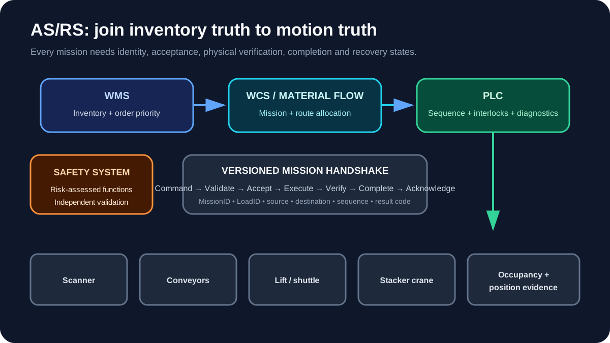
AS/RS control-layer responsibilities
| Layer | Owns | Must not assume |
|---|---|---|
| WMS | inventory, order priority, business location | a physical move happened because it was requested |
| WCS/material-flow controller | routing, mission allocation, traffic coordination | a PLC output means the load reached its destination |
| PLC | deterministic sequence, device control, interlocks, local diagnostics | inventory can be changed without transaction acknowledgement |
| Drive/servo controller | regulated motion under approved commands | route or inventory intent |
| Safety system | safety functions from the risk assessment | normal PLC status is proof of safety |
| Operator HMI | requests, status, guided recovery | direct uncontrolled writes to internal state |
Typical equipment
An AS/RS may include:
- infeed and outfeed conveyors;
- barcode or RFID identification;
- dimension and weight checks;
- pallet or tote centring;
- stacker cranes, shuttles, lifts or mobile robots;
- storage locations and position references;
- doors, gates, light curtains and emergency stops;
- WMS/WCS servers and network infrastructure.
The control design changes with technology. Do not force a crane aisle, cube shuttle and vertical lift module into one generic sequence.
1. Define a mission transaction
A mission should have an immutable identity and explicit lifecycle.
MissionID
LoadID
SourceLocation
DestinationLocation
LoadType
Priority
CommandSequence
StatusSequence
ResultCode
Recommended handshake:
- WCS writes a new command with a changed sequence number.
- PLC validates mode, fields and resource availability.
- PLC acknowledges acceptance or returns a rejection code.
- PLC executes state transitions.
- PLC reports completion only after destination presence/position is verified.
- WCS acknowledges the result.
- Both sides retire the transaction.
This prevents a stale “start” bit, duplicated packet or server restart from creating an untraceable second move.
2. Give every resource a state machine
Example conveyor zone:
EMPTY
  → RESERVED_FOR_INFEED
  → RECEIVING
  → OCCUPIED_VERIFIED
  → RESERVED_FOR_DISCHARGE
  → DISCHARGING
  → EMPTY
Abnormal branches include IDENTITY_MISMATCH, BLOCKED, DRIVE_FAULT, SENSOR_CONFLICT and RECOVERY_REQUIRED.
The zone should not become EMPTY merely because its motor ran. It becomes empty when the relevant sensors and downstream handshake prove transfer completion.
Live mini-lab
Try it: press START, then STOP
A stop-dominant seal-in rung: START latches the motor output through its own contact, and STOP breaks the circuit.
Watch the output lamp: it stays on after START until you press STOP.
Free · no signup to try · runs in your browserOpens plcsimulationsoftware.com — same team
3. Separate occupancy, identity and mission
These are three different facts:
- Occupancy: a sensor or control inference says a load is present.
- Identity: scanner/WCS data says which load it is.
- Mission: a transaction says where the load should go.
When they disagree, stop the transaction at the smallest safe boundary and present a recovery decision. Automatically rewriting inventory to match one sensor can turn a local fault into widespread inventory corruption.
4. Design permissives and interlocks
For a transfer from Conveyor A to Lift B:
Start permissives
- both resources in Auto and available;
- Lift B at the transfer level and position confirmed;
- destination zone reserved and clear;
- load identity accepted;
- drives ready;
- guarding/safety system permits the commanded movement;
- no conflicting mission owns either resource.
Run interlocks
- transfer path remains valid;
- drive and motion feedback stay healthy;
- load does not exceed tracking timeout;
- no unexpected sensor sequence occurs;
- receiving resource remains able to accept.
Write the cause of a blocked start separately from the cause of a running trip. Operators need to know whether they should wait, clear a downstream condition or call maintenance.
5. Build deterministic load tracking
Use edge events and state transitions, not one global “load present” bit. For each zone, capture:
- entry sensor transition;
- expected travel window;
- presence confirmation;
- exit transition;
- downstream acceptance;
- current mission/load identity;
- confidence/validity state.
Do not rely on timers alone to declare position. Timers detect “too long” or provide settling delay; sensors, encoders and verified handshakes establish location.
6. Recovery is a designed mode
Common recovery situations:
- load physically present but software location empty;
- two sensors occupied for one load;
- unreadable barcode;
- crane stopped between positions;
- WCS unavailable;
- drive replaced or homing lost;
- operator removed a load during isolation;
- power restored during a mission.
Recovery screens should:
- show physical evidence and software state;
- explain the inconsistency;
- restrict available actions to authorised roles;
- require confirmation of the physical condition;
- log who changed identity/location/state and why;
- revalidate the route before returning to Auto.
A generic “reset all faults” button is not a recovery strategy.
7. Safety boundary
AS/RS equipment can create crushing, trapping, falling-load and unexpected-motion hazards. Safety functions must come from a machine risk assessment and be designed, verified and validated by qualified practitioners.
ISO's ISO 13849-1:2023 overview describes a methodology for safety-related parts of control systems; it does not prescribe the safety functions or required performance level for a specific AS/RS. In the United States, OSHA's control-of-hazardous-energy standard covers servicing situations where unexpected energisation or stored-energy release could injure workers.
Ordinary PLC logic, WCS permissions and HMI passwords are not substitutes for required safety functions or energy isolation.
8. Communications and degraded modes
Define behaviour for:
| Lost service | Minimum decision |
|---|---|
| WMS unavailable | Finish accepted mission, pause, or controlled local buffer? |
| WCS unavailable | Which equipment may finish and which must stop accepting loads? |
| PLC-to-PLC link lost | Safe equipment boundary and stale-data timeout |
| Scanner unavailable | Reject, quarantine or authorised manual identity entry |
| Time synchronisation lost | How event order and audit records remain interpretable |
| Network path degraded | Alarm threshold, redundancy response and maintenance action |
Do not continue indefinitely on cached missions unless capacity, inventory and recovery behaviour are explicitly designed.
9. FAT test matrix
Normal missions
- store from every valid infeed to representative locations;
- retrieve to every outfeed;
- route through alternate paths;
- handle priority and cancellation at allowed states;
- verify identity at each transfer boundary.
Abnormal missions
- destination becomes occupied;
- source load absent;
- duplicate MissionID or sequence number;
- unreadable/mismatched barcode;
- sensor stuck on/off;
- drive not ready or feedback lost;
- communication lost before acceptance, during motion and after completion;
- controller/WCS restart at each mission state.
Recovery
- reconcile physical load with empty software state;
- remove a load under lockout and reintroduce the aisle;
- restore homing/reference;
- resolve double occupancy;
- prove audit log and role restrictions.
AS/RS diagnostics that reduce downtime
- current mission, load and route;
- equipment state with time in state;
- first-out blocking permissive;
- first-out trip/interlock;
- sensor sequence expected vs observed;
- stale-data timers and connection state;
- location confidence/validation status;
- recovery action history;
- network and drive diagnostic summary.
Primary references
- MHI, Automated Storage/Retrieval Systems industry group.
- ISO, ISO 13849-1:2023 overview.
- U.S. OSHA, 29 CFR 1910.147—control of hazardous energy.
Related guides
Now run it · free · no signup
Run your first PLC program in your browser
Build one rung, press Run and watch the output change in a free browser lab. Nothing to install and no signup needed to try it.
Ownership disclosure: PLC Programming IO and PLC Simulation Software are operated by the same publisher.


