VFD Setup and Wiring for PLC-Controlled Motors
Plan, wire and commission a variable frequency drive with correct power architecture, motor data, PLC command sources, EMC controls, STO boundaries and acceptance evidence.
Review status: Editorially reviewed against cited ABB, Danfoss, Rockwell Automation, Schneider Electric, NIST and OSHA materials; exact protection, conductors, terminals, parameters, EMC, STO and safe commissioning requirements must come from the installed equipment design and current manuals
Direct answer
Set up a variable frequency drive by treating it as a power-conversion system, a motor-control system and a machine-control interface—not as a three-phase contactor with a speed knob. A qualified design must match the supply, available fault current, drive rating, enclosure/environment, motor type and nameplate, load torque/speed duty, stopping energy, cable length, upstream protection, protective earthing, electromagnetic compatibility and required safety functions. Use the exact drive hardware, programming, safety and motor manuals; terminal numbers and permissible devices are model-specific.
For a common PLC-controlled arrangement, protected supply power feeds the VFD input; the VFD's PWM output feeds only the selected motor; protective earth and shield/bonding follow the manufacturer EMC design; PLC digital, analog or network signals provide ordinary commands and references; and an independently designed safety circuit uses the drive's certified Safe Torque Off function when the risk assessment requires it. The PLC should receive ready, running, at-reference and fault/status evidence instead of inferring operation from its own run command.
Commission in controlled gates. Preserve the factory/as-found configuration, inspect the de-energized installation, verify absence of voltage by the product/site procedure, enter motor nameplate data, define command and speed-reference sources, set limits and acceleration/deceleration behavior, prove safety and stop categories, perform only the manufacturer-approved stationary/direction/autotune tests with the zone clear, then test load, thermal behavior, feedback, loss/recovery and documentation. Never use this article as an installable wiring diagram.
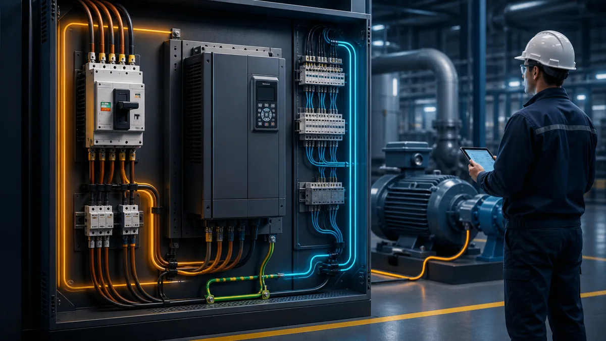
Establish the design and safety boundary
A VFD can retain hazardous DC-bus voltage after input power is removed. A rotating permanent-magnet motor or process can generate voltage. External control supplies can keep terminals energized. The manufacturer's stated discharge time and absence-of-voltage procedure are mandatory inputs, not generic suggestions.
Build the evidence pack before touching terminals
| Required evidence | What it must identify | Why a generic diagram is insufficient |
|---|---|---|
| drive identity | full catalogue number, frame, ratings, hardware/firmware and options | terminals, current, clearances, protection and safety functions vary |
| drive hardware manual | supply system, SCCR/fault-current conditions, protection, cable, PE, EMC and terminal data | related family members can have different power structures |
| programming manual | motor model, nameplate fields, limits, source logic, ramps and diagnostics | parameter codes/defaults change by product and revision |
| safety manual | STO or other safety-function architecture, diagnostics and validation | ordinary control wiring cannot establish claimed PL/SIL behavior |
| motor data | type, connection, voltage/current/frequency/speed/power, insulation and permissible VFD duty | drive size alone does not prove motor compatibility |
| application duty | load torque curve, speed range, acceleration, reversing, inertia and stopping frequency | fan, conveyor, hoist and spindle needs differ materially |
| electrical design | supply, earthing system, available fault current, disconnect, branch protection and conductors | upstream equipment must satisfy local code and drive listing/manual |
| cable/environment | motor cable construction/length, routing, ambient, altitude, enclosure and contamination | derating, output filters, EMC and motor stress depend on installation |
| controls/safety narrative | command sources, modes, interlocks, stop categories, restart and loss behavior | “run from PLC” does not define authority or safe response |
| acceptance plan | predicted results for de-energized, no-load, loaded and fault/recovery tests | energization without criteria becomes trial-and-error |
Rockwell's current PowerFlex 520-series manual explicitly states that the drive does not provide branch short-circuit protection and calls for selected input fuses or a circuit breaker under applicable codes. This is one product example of a broader rule: read the installed drive's protection tables and conditions. Never assume the VFD replaces the upstream disconnect, branch protection, earth-fault design or machine isolation.
Separate isolation, stopping and torque prevention
| Function | Practical purpose | What it does not automatically do |
|---|---|---|
| supply disconnect/isolation | establish an isolation point for electrical work when designed and applied correctly | guarantee DC bus is discharged or external control power is absent |
| normal VFD stop command | decelerate or coast according to programmed operating logic | isolate hazardous electrical energy or provide a certified safety function |
| Safe Torque Off | prevent torque-producing energy to the motor using the certified drive safety function | disconnect mains/DC bus, prevent a coasting load, hold a suspended load or prove zero speed |
| mechanical brake | hold/stop load when selected, controlled and monitored for the application | remove electrical hazards or replace STO design by itself |
| emergency stop function | reduce risk through the machine's validated stop architecture | imply one universal category, wiring or restart behavior |
| lockout/tagout | control hazardous energy for servicing through site/legal procedure | follow automatically from pressing STOP or opening a standard PLC bit |
OSHA's control-of-hazardous-energy rule and the drive manual govern servicing in the applicable jurisdiction. Schneider's ATV320 getting-started material directs trained personnel to disconnect all power including external control power, lock switches open, wait the product-specific discharge time and perform its absence-of-voltage verification. The exact procedure and time belong to the exact product/manual and site—not to this guide.
Match the VFD, supply, motor and load
Selecting only by motor kW or horsepower can produce an installation that lacks voltage compatibility, current capacity, overload duty, environmental rating, braking capability or motor insulation protection. Use the drive manufacturer selection method and local electrical design.
Create a selection matrix
| Design item | Evidence | Consequence if wrong |
|---|---|---|
| supply voltage/phases/frequency | measured/design supply range and drive input rating | damage, undervoltage/overvoltage trips or unavailable output |
| available fault current | study/design value at drive and approved SCCR combination | protection/listing may be invalid; severe fault hazard |
| drive output current | motor current across load, ambient, altitude, carrier frequency and overload class | overheating, nuisance trips or inadequate torque |
| motor type/control | induction, permanent-magnet or synchronous reluctance plus supported drive algorithm | failed tuning, instability or motor damage |
| load torque profile | variable torque, constant torque, shock/overhauling load and duty cycle | wrong drive duty/ramp/braking selection |
| speed range | minimum/maximum continuous speed and motor cooling | motor overheats at low self-cooled speed or overspeeds load |
| stopping energy | inertia, decel time, cycle and overhauling energy | DC-bus overvoltage or overheated brake equipment |
| environment | temperature, altitude, dust, moisture, chemical, vibration and enclosure | derating or enclosure/cooling failure |
| motor cable | type, length, capacitance, parallel runs and routing | motor terminal overvoltage, reflected-wave/EMC and drive loading issues |
| safety function | required PL/SIL/stop behavior and proof-test/diagnostics | ordinary control mistaken for risk reduction |
| network/control | protocol, I/O, encoder/feedback, time and redundancy needs | missing command/status capability or brittle gateway design |
Record motor compatibility, not only nameplate power
An inverter-duty motor is designed with PWM supply stresses in mind, but suitability still depends on voltage, cable length, switching behavior, speed range, bearing currents, cooling, hazardous-area certification and manufacturer limits. A legacy general-purpose motor may require output filtering, reduced cable length, insulated bearings or replacement after an engineering review. Do not infer compatibility from “it ran on a starter.”
For multi-motor operation, switching devices between VFD and motors, bypass contactors, output reactors/filters, sine filters, brake resistors, regenerative units or line reactors, follow a designed manufacturer-supported topology. Opening a contactor on a live PWM output, connecting power-factor-correction capacitors at the output, or applying incoming mains to output terminals can damage equipment. Exact restrictions are product-specific.
Design the VFD power path
The power path includes the supply/earthing system, isolating means, branch short-circuit protection, any approved input conditioning, VFD input, DC link, PWM inverter, output treatment where required, motor cable, motor and protective bonding. The VFD changes voltage and frequency at its output; it does not turn the motor circuit into ordinary sinusoidal utility power.
Keep line and motor sides unambiguous
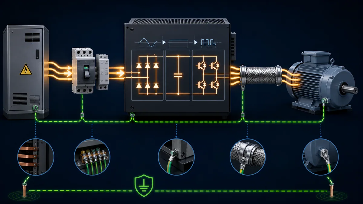
| Power-path check | Design question | Acceptance evidence |
|---|---|---|
| source/earthing system | is the drive/filter approved for grounded, corner-grounded, impedance-grounded or ungrounded supply as installed? | exact manual configuration and electrical design match |
| disconnect | does the device isolate every required source and meet code/site visibility/lockability? | approved one-line and isolation test/procedure |
| branch protection | are device type/rating and available current within manufacturer/listing tables? | coordination/SCCR record and installed catalogue identity |
| line impedance | are line reactor/choke/transformer conditions required or prohibited? | supply study and vendor selection evidence |
| input/output identity | are line terminals and motor terminals positively identified before landing conductors? | point-to-point de-energized inspection and torque record |
| conductor/terminal | material, cross-section, temperature rating, lugs and torque accepted? | product table, code calculation and calibrated-tool record |
| PE/bonding | drive, cabinet, motor and cable-shield arrangement follows design? | continuity/bonding evidence under approved method |
| motor cable/filter | type/length and output reactor, dV/dt or sine-filter need resolved? | installed route/as-built and motor/drive calculation |
| brake path | resistor/regenerative equipment rating, protection and location approved? | energy/thermal design and function test |
| bypass/switching | interlocking and transfer rules prevent invalid output switching/backfeed? | reviewed schematic and controlled sequence test |
Do not publish or reuse one universal terminal scheme. ABB commonly labels an input group and motor output group in its ACS580 manuals; Danfoss and Rockwell use their own identifiers; Schneider varies by range and frame. A related drive can place DC-bus, brake and PE connections close to power terminals, making visual guesswork especially hazardous.
Resolve leakage current and residual-current protection
VFD input filters and motor cables can produce leakage/common-mode current and DC components. The correct RCD/GFCI/RCM type, sensitivity, selectivity and upstream arrangement depend on the drive manual, supply system, local code and whole installation. A device selected as though the load were a simple motor may nuisance-trip or fail to meet the intended protection. Document the drive's specified conditions and cumulative leakage from multiple drives.
Build an EMC-conscious cabinet and cable route
PWM edges create common-mode and differential-mode interference paths. EMC performance depends on the physical installation: bonding impedance, shield termination, cable construction, separation, cabinet entry and route are part of the circuit at high frequency.
Separate power and control by design
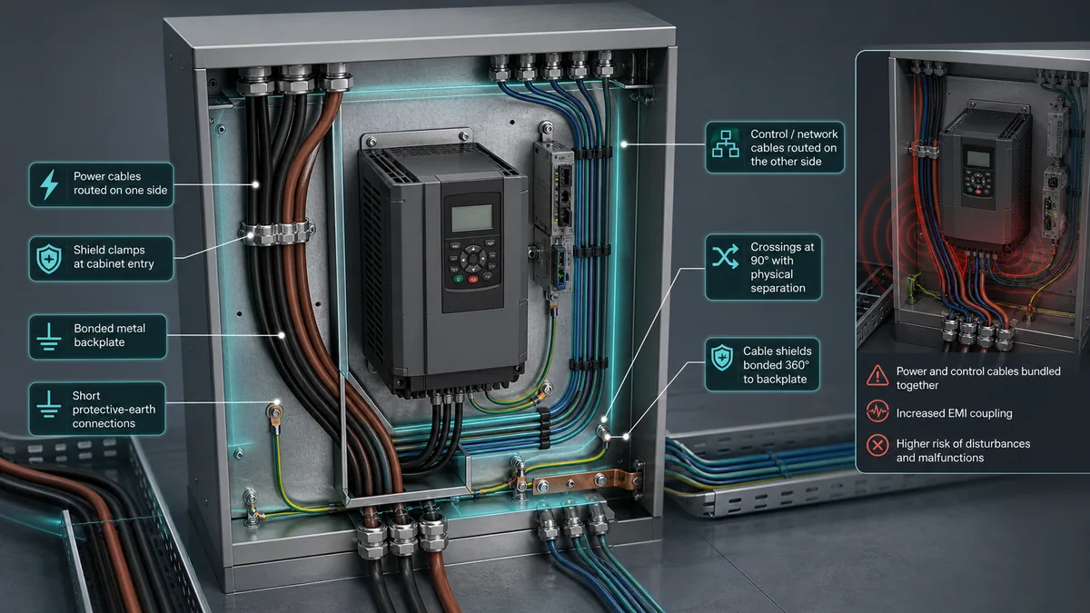
| EMC element | Strong installation evidence | Weak shortcut |
|---|---|---|
| conductive backplate/enclosure | bare-metal or approved bonding treatment and verified continuity | assuming painted mounting screws create HF bond |
| motor-cable shield | drive-approved cable and termination with high-frequency contact at required ends/entries | long pigtail used as the only shield connection when manual requires 360° clamp |
| PE conductor | code/manual compliant protective conductor with short direct route | treating cable shield as the only protective earth |
| cable zones | input power, motor output, brake, control, encoder and network routed per separation rules | bundling every cable in one tray because insulation ratings match |
| crossings | minimized and arranged according to manufacturer guidance, commonly near right angles | long parallel runs of analog/encoder beside motor output |
| control reference | analog common/reference and shield applied exactly as signal/manual design | bonding commons randomly at both ends |
| cabinet entry | shields/bonds/glands established at defined entry, not after long unshielded tails | shield left floating through gland plate |
| filter/reactor placement | vendor-approved device located and bonded with short connections | generic filter added remotely with long unscreened conductors |
| motor frame | robust protective bonding and manufacturer shield termination | relying on mechanical mounting through corrosion/paint |
| measurement | baseline noise, communication and earth/bond evidence under operating load | declaring EMC good because the motor turns in an empty shop |
ABB's ACS580 hardware documentation distinguishes power, motor and control cable entries and describes shield grounding. Danfoss's design guide includes a dedicated EMC-compliant installation section. Rockwell provides separate PWM-drive wiring/grounding and installation-considerations publications. Use the product-specific combination because shield instructions can change with enclosure, filter, cable and compliance category.
Protect sensitive feedback and instrumentation
Route encoder, thermistor, analog, network and safety conductors according to their product manuals. Use differential/current signals where the system design supports them; confirm analog input mode and switch/jumper configuration before applying a voltage/current signal; and avoid using PLC analog common, PE and shield as interchangeable conductors. Prove polarity, range, scale, fault behavior and noise at low, mid and high speed.
Live mini-lab
Try it: press START, then STOP
A stop-dominant seal-in rung: START latches the motor output through its own contact, and STOP breaks the circuit.
Watch the output lamp: it stays on after START until you press STOP.
Free · no signup to try · runs in your browserOpens plcsimulationsoftware.com — same team
Choose the PLC-to-VFD control method
The main ordinary-control choices are hardwired digital commands, analog speed/torque reference and an industrial network. Many machines combine them—for example, safety through STO, enable/run through digital logic, and setpoint/status through a network. Define one active owner per command and reference in every mode.
Compare control interfaces
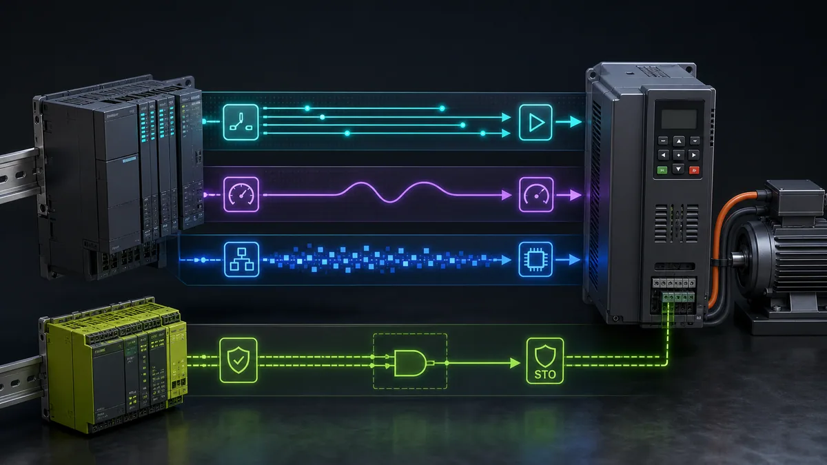
| Method | Advantages | Design risks | Evidence to expose back to PLC/HMI |
|---|---|---|---|
| two-wire digital run | simple maintained state and familiar terminals | automatic restart if state remains true unless restart logic prevents it | ready, enabled, running, direction, fault and local/remote |
| three-wire start/stop | momentary start with maintained internal run latch behavior | terminal function/product semantics vary; network/local mode can override | active source and actual run latch/state |
| preset speeds | deterministic choices without analog noise | limited resolution and bit-combination ambiguity | selected/active preset and at-speed |
| analog reference | broadly compatible and visible with measurement | scaling, common-mode, mode switch, open-circuit and noise errors | raw input, engineering reference, source and loss response |
| industrial network | rich commands, setpoints, status, diagnostics and parameter access | assembly/profile mismatch, stale data, ownership and reconnect behavior | connection, command/reference owner, status word, actual speed/current and fault |
| local keypad | valuable for controlled setup and maintenance | machine PLC may believe it owns motion when drive is local | local/remote/source status and inhibited automatic sequence |
| safety input/STO | certified torque-prevention channel when applied to safety manual | not normal stop, isolation, brake control or zero-speed proof | safety status/diagnostics for display only; safety logic remains validated |
Rockwell's PowerFlex 520-series control diagram, for example, distinguishes sink/source wiring and notes specific two-wire versus three-wire behavior. Danfoss documents selectable NPN/PNP digital-input behavior on relevant products. Schneider's ATV320 uses source/sink selector arrangements that vary by form factor. The useful general lesson is to record the actual electrical input type, internal/external supply, common, logic state and parameter assignment—never to copy terminal numbers across brands.
Define command and reference ownership by mode
| Machine mode | Run owner | Speed/reference owner | Required transition behavior |
|---|---|---|---|
| off/maintenance isolated | no ordinary run authority | none | electrical isolation and site procedure govern work |
| local maintenance | authorized local station/keypad under procedure | local jog/reference with bounded limits | automatic PLC commands inhibited; source clearly indicated |
| manual HMI | PLC application validates operator request | PLC or selected bounded HMI setpoint | interlocks and command acknowledgement active |
| automatic | PLC sequence | recipe/controller/network value | mode entry starts only through explicit permissive logic |
| communication loss | defined stop/hold/fallback per risk assessment | defined fallback; never accidental retained stale value | alarm and controlled reconnection; no unexpected restart |
| safety demand | safety system | irrelevant until safe restart conditions met | STO/brake/contactor logic follows validated safety design |
Avoid programming a drive so that a keypad, terminal and network can all command motion without a documented priority. Drive source status should be available to the PLC/HMI. A machine that displays “automatic” while the VFD is in local mode has a dangerous observability gap even if the motor is currently stopped.
Wire analog references as measured signals
For a 0–10 V or 4–20 mA reference, confirm the VFD input mode, electrical range, common/reference, isolation and cable/shield instructions. At commissioning, inject safe traceable low/mid/high points, read both the measured input and drive's internal displayed value, and compare requested frequency/speed. Define behavior below range, above range and on open circuit. A 4 mA live zero can support wire-break distinction when both endpoints and configuration implement it; it does not automatically make the circuit fault-tolerant.
Keep STO and machine safety separate from standard control
Safe Torque Off is a certified drive function that disables torque-producing energy through the specified safety channels. It normally lets the DC bus remain energized and does not physically disconnect the motor. A gravity load can fall, a high-inertia load can coast, and a permanent-magnet motor can still generate voltage while turning.
Safety-function design questions
| Question | Required evidence | Unsafe assumption |
|---|---|---|
| what hazard must be reduced? | machine risk assessment and required stop behavior | “STO means the machine is safe” |
| what performance is required? | PL/SIL/category and mission-time/diagnostic design | using standard PLC output because it turns STO off in a test |
| how many channels and what test pulses? | exact drive safety manual and safety-controller compatibility | joining channels or suppressing diagnostics to clear a fault |
| does load need controlled deceleration first? | stop category, timing and failure analysis | applying STO immediately to every process regardless of coast hazard |
| is a mechanical brake required? | load-holding analysis, brake control and monitoring | expecting motor torque to hold after STO |
| how is reset/restart controlled? | deliberate reset outside hazard and prevention of unexpected restart | restoring STO automatically starts retained run command |
| is zero speed/position needed? | suitable monitored safety function/device | treating STO status as zero-speed proof |
| how is it validated? | safety requirements specification and recorded functional tests/fault cases | one successful stop button test proves the safety lifecycle |
Use the exact drive's safety-functions manual. A drive family may offer STO only or additional functions through an option; ratings and wiring can differ by hardware revision. Standard PLC status can mirror the safety state for diagnostics, but it must not become an unvalidated part of the safety decision.
Enter motor data and operating limits
The motor nameplate is the authoritative starting point for motor voltage, current, frequency, speed and power. Also record connection configuration, duty, service factor where applicable, efficiency/power factor if required by the drive model, encoder data and thermal sensor. Use the motor's rating for the actual connection—not an assumed regional default.
Create a parameter worksheet before energization
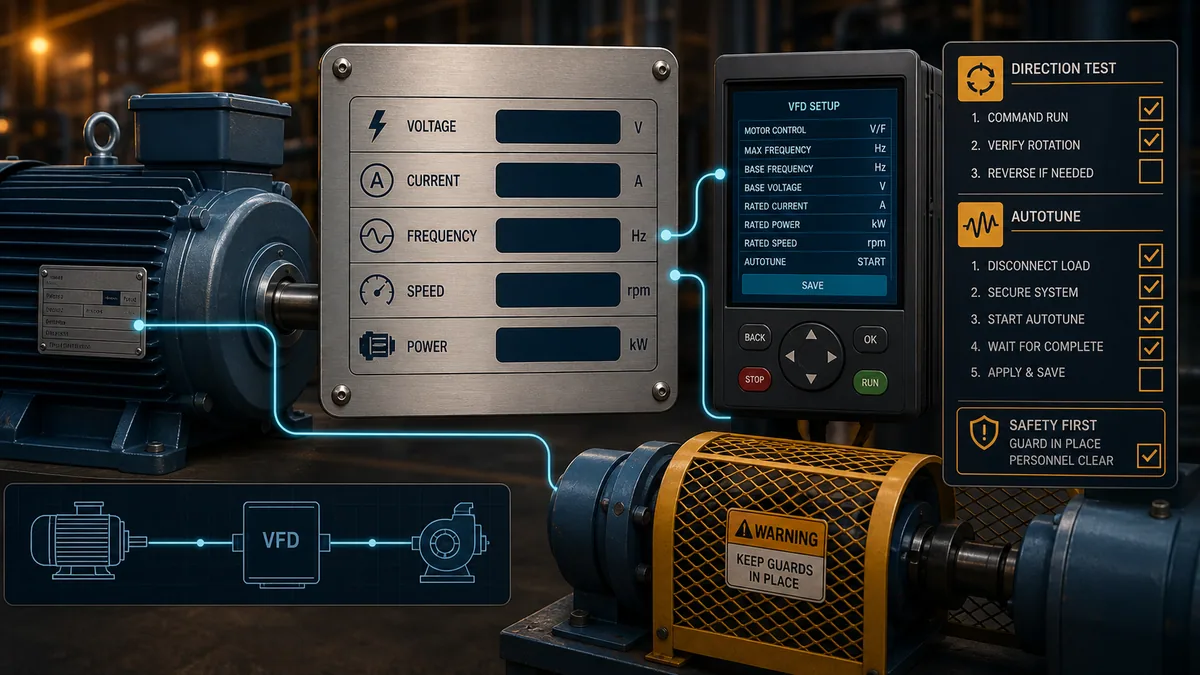
| Parameter group | Source | Verification |
|---|---|---|
| motor control mode/type | motor and drive manuals plus application duty | exact motor technology and feedback match selected algorithm |
| rated voltage/current | installed motor nameplate at its wired connection | photograph and two-person transcription check |
| rated frequency/speed | motor nameplate | base point and pole/slip relationship are plausible |
| rated power | motor nameplate and unit convention | kW/hp setting and drive range correct |
| minimum/maximum speed | machine, motor, load and cooling limits | no mechanical overspeed; low-speed thermal duty addressed |
| acceleration/deceleration | inertia, torque, process and stopping design | test without current limit/DC-bus overvoltage or process upset |
| current/torque limits | motor, drive and machine requirements | protection and process torque both satisfied |
| stop/brake mode | risk/process and stopping-energy design | coast/ramp/DC injection/brake behavior intentionally selected |
| carrier/switching frequency | drive/motor/cable/ambient requirements | current derating, noise, heating and cable stress evaluated |
| command/reference source | controls narrative | keypad/terminal/network ownership matches each mode |
| digital/analog/network map | I/O/network schedule | every signal's polarity, scaling and loss behavior tested |
| restart/catch-on-fly | risk assessment and driven-process behavior | no unexpected restart or unsafe spinning-load capture |
Schneider's ATV320 quick-start material identifies a common sequence: motor nameplate power, voltage, current, frequency and speed, followed by motor thermal current and basic ramps/speed limits. That is product-specific parameterization but a sound general order. Do not enter the VFD's output rating as the motor current merely because it is readily visible.
Treat auto-identification as a motion-capable test
Drive “autotune,” “motor identification” or adaptation routines vary. Some are stationary; some rotate the motor; some require uncoupling or a particular load state; some need the motor cold; some are inappropriate for certain motors or processes. Schneider warns that applicable autotuning can move the motor. Rockwell includes a direction test before autotune for certain permanent-magnet/feedback workflows. ABB separates motor identification from later control-loop autotuning in some control programs.
Before starting, follow the exact manual, clear/guard the hazard zone, establish who controls the test, confirm brakes and driven load behavior, set limits, ensure emergency/safety functions are validated for the test state and communicate that movement may occur. Store the result and configuration revision; repeat only when changes such as motor or cable replacement require it under the manual.
Set ramps, limits and stopping behavior
An aggressive acceleration can hit current/torque limit and stretch the actual ramp. An aggressive deceleration can return energy to the DC link and cause an overvoltage trip unless the system can dissipate or regenerate it. The process can also impose pressure surge, belt slip, mechanical shock or unstable control.
Match drive dynamics to the process
| Application behavior | Setup focus | Test evidence |
|---|---|---|
| centrifugal fan/pump | minimum flow/speed, resonance skips, sleep/wake, variable-torque duty | process curve, vibration and thermal behavior across range |
| conveyor | breakaway torque, acceleration, load retention, jam/current limit and restart | empty/loaded starts, stops and loss recovery |
| high inertia | acceleration time, decel energy, brake/regeneration and coast hazard | DC-bus/brake thermal data and repeated duty test |
| overhauling/gravity | four-quadrant energy, mechanical brake and safety | worst load direction and brake handoff validation |
| positive-displacement pump/compressor | minimum speed, pressure/flow protection and unloaded start | manufacturer/process limits and trip response |
| multi-speed machine | skip frequencies, resonance, mechanical max and command transitions | dwell through range plus stable points |
| closed-loop speed/position | encoder polarity/resolution, tuning, task/network and overspeed | direction test, feedback loss and dynamic response |
Do not lengthen deceleration simply to hide every DC-bus fault without checking process stopping needs. Conversely, adding a brake resistor without calculating power, energy, duty, thermal protection and drive compatibility is not a safe shortcut. Use the selected manufacturer's sizing method.
Commission the VFD through controlled gates
Each gate should have an owner, prerequisites, predicted result, measurements and stop condition. The exact energization procedure comes from the site and manufacturer.
Six commissioning gates
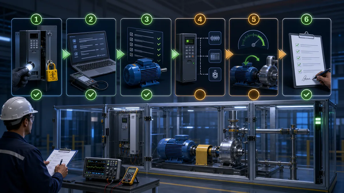
| Gate | Core actions | Exit evidence |
|---|---|---|
| 1 — document and isolate | identify equipment/configuration; apply site energy-control procedure; inspect against drawings/manuals | correct identities, safe work state, resolved deviations |
| 2 — de-energized electrical/mechanical | conductors, terminals/torque record, PE/bonding, shield, cable routes, motor connection, guards and load | signed inspection and approved test results; no power megger applied through electronics |
| 3 — configure without motion | backup/reset decision, motor data, limits, source selection, I/O/network, stop/restart and safety parameters | peer-reviewed parameter comparison and correct source/status |
| 4 — validate safety and control permissives | STO/safety lifecycle tests, run inhibition, local/remote, fault reset and loss states | validated safe response and no retained unexpected run |
| 5 — controlled motor tests | manufacturer-approved ID/autotune, low-speed direction and uncoupled/coupled sequence as designed | correct rotation/feedback, stable current and no abnormal mechanical condition |
| 6 — loaded acceptance and handover | ramps, full range/duty, thermal, process interlocks, network loss/recovery, alarms and backups | signed results, as-built/configuration, baseline trends and trained owners |
Never insulation-resistance test a circuit through connected VFD electronics unless the exact manufacturer procedure permits it; isolate the drive/motor as instructed. Do not swap input and output conductors to correct rotation. If the manufacturer/design permits phase swapping on the motor side, perform it only in the established de-energized work state; many drives also provide a controlled direction parameter, but the machine's forward definition and feedback polarity still require validation.
Acceptance test matrix
| Test | Stimulus | Expected result | Evidence to retain |
|---|---|---|---|
| identity/configuration | compare drive/motor/options/firmware and parameter file | approved exact system and version | photos, export/checksum and comparison report |
| power-up inhibited | energize with all run sources proven inactive | drive ready or defined safe state; no motion | source/status, DC/supply diagnostics and observation |
| command ownership | select local/manual/auto one at a time | only authorized source can request run/reference | mode-source matrix and PLC/HMI indications |
| digital inputs | actuate each through approved test | raw input, assigned function and logic polarity agree | I/O trace and predicted result |
| analog reference | inject low/mid/high and fault values | raw/engineering reference and loss behavior agree | calibration points and scale calculation |
| network | command/read approved data then interrupt/recover | status freshness, fallback and no unintended restart | packet/status trace and sequence record |
| STO/safety | execute validated safety test/fault cases | torque prevention/stop/brake/reset behavior meets SRS | formal safety-validation record |
| direction/feedback | guarded low-energy test | machine forward and feedback polarity agree | observer/test state and result |
| ramp/current | empty and representative loaded cycles | actual ramp, current/torque limit and process response acceptable | trend of reference, actual, current and DC bus |
| stop/braking | each normal/protective stop under defined load | stop time/behavior and brake thermal duty within design | measured stop time and repeated-duty data |
| speed range | dwell at approved minimum, critical and maximum points | cooling, vibration, current and process stable | temperature/vibration/process baseline |
| fault/reset/restart | inject approved safe faults and power/control loss | actionable diagnostics; deliberate recovery; no surprise motion | fault/event log and restart checklist |
Use the VFD simulator to rehearse command ownership, motor data, ramps, drive status and safe diagnostic decisions before working with a physical drive. Simulation does not validate conductors, fault protection, motor insulation, STO hardware or machine safety.
Diagnose setup errors without replacing hardware
This page focuses on finding setup and wiring mismatches during commissioning. For in-service motor/drive fault isolation, use the PLC motor and drive troubleshooting guide. Preserve the drive's raw status, active command/reference sources, first fault and parameter/configuration before reset.
Commissioning symptom matrix
| Symptom | First discriminating evidence | Common setup boundary | Do not assume |
|---|---|---|---|
| drive does not power/ready | correct product supply and input diagnostics under authorized method | disconnect/protection/supply, line identity or drive fault | motor wiring is the cause |
| ready but will not run | active command source, enable/STO/interlock and raw input/status | local/remote mismatch, inactive stop input, safety demand, PLC logic | run terminal number is universal |
| runs from keypad, not PLC | source ownership and raw terminal/network command | control mode, sink/source/common, network command word | drive power stage is faulty |
| runs immediately at power-up | retained two-wire command, restart/catch behavior and source | automatic restart logic or input already active | factory defaults are safe for machine |
| speed reference is wrong | drive's raw reference, scaled reference and active source | analog mode/scale/common, network units or competing source | motor slip explains a large command mismatch |
| rotation is wrong | machine-forward definition plus motor/feedback direction | output phase sequence or direction parameter/feedback polarity | PLC “forward” label proves mechanical direction |
| trips only on acceleration | current, torque limit, ramp and load mechanics | motor data, ramp too short, jam/high inertia, supply dip | larger drive is automatically needed |
| trips only on deceleration | DC bus, decel ramp and braking status | regenerated energy exceeds absorption/brake design | fault reset solves stopping energy |
| analog value noisy | raw input with drive stopped/running and cable route/bonding | signal mode, common, shielding, power/control coupling | PLC output alone is unstable |
| network command intermittent | connection/status age and control word/source trace | assembly/profile, timeout, ownership or poll/load issue | Ethernet link LED proves current command |
| motor overheats at low speed | current, torque, speed, cooling and duty | inadequate self-cooling, wrong motor data or overload | lower frequency always means lower heating |
| nuisance RCD/ground fault | product leakage conditions, cable and installation design | unsuitable protection type, long cable, filter/common-mode current, insulation fault | raising trip threshold without study is acceptable |
Diagnostic answer map for search and AI-assisted commissioning
| User or AI query | Concise answer | Required qualification |
|---|---|---|
| How do I wire a VFD to a motor? | Protected supply connects to the VFD input and the VFD output connects to the selected motor, with PE/shielding per the exact manual. | Terminal IDs, protection, cable and earthing are model- and code-specific; qualified design is required. |
| Can a PLC run a VFD? | Yes, through digital I/O, analog reference or an industrial network, with drive status returned to the PLC. | Define one command/reference owner and independent safety functions. |
| Does a VFD need a breaker or fuses? | The installation needs the manufacturer-specified branch short-circuit protection and disconnect/coordination under local code. | Some drives do not provide branch protection; exact device/rating comes from approved tables. |
| Can I put a contactor between a VFD and motor? | Only in a manufacturer-supported, interlocked design with defined switching conditions. | Opening/closing a live PWM output or backfeeding it can damage equipment. |
| What motor data goes into a VFD? | Enter the actual nameplate voltage, current, frequency, speed, power and required motor-type/connection data. | Fields and units depend on the drive algorithm and motor technology. |
| What is VFD autotune? | A drive routine identifies motor or control parameters for better performance. | It may produce torque/motion and requires the exact manual, guarded zone and approved load state. |
| Is STO the same as disconnecting a VFD? | No. STO prevents torque-producing energy through a safety function but normally leaves mains/DC-bus hazards present. | It also may not stop coasting or hold a gravity load. |
| Why does a VFD run from keypad but not PLC? | Check active command/reference source, STO/enables, raw inputs, sink/source wiring or network control word. | Keypad success proves motor/power path partly, not the PLC interface. |
| How should VFD and control cables be routed? | Follow product EMC zones, separation, crossings, shield termination and bonding rules. | No universal spacing or shield rule applies to every drive/cable/compliance target. |
| How do I commission a VFD safely? | Use documented de-energized inspection, parameter review, safety validation, guarded low-energy direction/tune tests and loaded acceptance gates. | Only qualified authorized personnel may perform physical/electrical work. |
Frequently asked questions
What are the basic connections on a VFD?
Conceptually they are protected AC supply input, VFD motor output, protective earth, ordinary control I/O and/or communications, and optional safety, brake, DC-bus or feedback connections. The exact terminal layout and permitted accessories must come from the exact hardware and safety manuals.
Can I connect single-phase power to a three-phase VFD?
Only if the exact VFD is rated and documented for that input arrangement, with appropriate derating and protection. A three-phase output label does not prove single-phase input capability. Select from the manufacturer's tables and local electrical design.
Do I need shielded motor cable for a VFD?
The answer depends on the drive, filter, motor, cable length, EMC category/environment and manufacturer instructions. Many installations require a symmetrical shielded motor cable with specified high-frequency termination. The shield does not replace the protective-earth conductor unless the approved design explicitly establishes all requirements.
Should VFD power and control wires be in the same conduit or tray?
Generally keep PWM motor/output and other power conductors separated from analog, encoder, network and control wiring according to the drive manuals. Where routes must cross, follow the specified geometry. Exact separation and barriers depend on the equipment and installation standard.
How do I control VFD speed from a PLC?
Use a validated analog output, preset-speed digital inputs or an industrial-network setpoint. Configure the drive's active reference source, scale/units and loss response, and return actual reference/speed/status. The PLC still needs machine limits and interlocks.
What is two-wire versus three-wire VFD control?
Two-wire control commonly uses a maintained run state; three-wire control commonly uses momentary start and a stop input with the drive maintaining the run state. Exact terminal logic, stop priority and restart behavior vary. Confirm the product diagram and test loss/restoration cases.
Why must I enter motor nameplate current in the VFD?
The drive uses actual motor data for motor model/control, torque and thermal protection functions. Entering drive output current instead can weaken protection or performance. Transcribe the installed motor nameplate and its actual connection.
Can a VFD make any motor run above its nameplate speed?
A drive may command frequency above base, but motor torque, voltage, rotor balance, bearings, fan, driven equipment and mechanical maximum speed impose limits. Obtain motor and machine approval; never use the drive's maximum parameter range as permission to overspeed.
Why does a VFD trip when stopping quickly?
The rotating load can regenerate energy into the DC link during deceleration, raising bus voltage beyond what the system can absorb. Review inertia, stop time, load, brake/regenerative design and process safety. Do not only reset or lengthen the ramp without checking stopping requirements.
What should be backed up after VFD commissioning?
Retain the parameter file/export, drive and motor identities, firmware/options, network/I/O map, safety validation, acceptance trends, as-built drawings, checksum/version, baseline fault/status data and restore instructions. Verify that the backup can be read and restored with controlled tools.
Sources, review scope, and limitations
This guide was reviewed on August 28, 2026 against current public manufacturer and regulator material. Product documentation can change with hardware, frame, firmware, region, supply system and certification. Use the exact documents supplied for the installed catalogue number and retain the tested revision in the project record.
- ACS580-01 drives manuals and current hardware/firmware documents — ABB
- ACS580-07 hardware manual — ABB
- VLT AutomationDrive FC 301/302 design guide and electrical-installation considerations — Danfoss
- VLT AutomationDrive FC 302 operating guide and wiring architecture — Danfoss
- PowerFlex 520-series Adjustable Frequency AC Drive User Manual, 520-UM001 — Rockwell Automation
- PowerFlex 525 product information and control I/O overview — Rockwell Automation
- ATV320 installation manual — Schneider Electric
- ATV320 programming manual — Schneider Electric
- ATV320 getting-started guide — Schneider Electric
- ATV320 safety functions and other product manuals — Schneider Electric
- NIST SP 800-82 Rev. 3, Guide to Operational Technology Security
- 29 CFR 1910.147, control of hazardous energy — OSHA
The images are conceptual and are not power, control, STO, earthing or terminal diagrams. This page does not specify conductor sizes, overcurrent devices, SCCR combinations, arc-flash boundaries, discharge times, torque values, shield connections, safety ratings or parameter values for any installation. VFD systems expose hazardous voltage, stored energy, unexpected movement and rotating/mechanical hazards. Only qualified, authorized personnel following the site risk assessment, electrical code, energy-control procedure, manufacturer instructions, engineered drawings, change control and functional-safety lifecycle should install, energize, tune, test or maintain them.
Now run it · free · no signup
Enable a VFD and set its speed in your browser
Give the drive run permission, set a speed reference and stop it safely while watching live frequency and motor speed. No signup required to finish the lab.
Ownership disclosure: PLC Programming IO and PLC Simulation Software are operated by the same publisher.
PLC Programming IO Editorial Team
Industrial automation education, references, and software testing
The PLC Programming IO Editorial Team publishes sourced industrial-automation education and documents how material is reviewed, tested, and corrected. A team byline means the publisher is responsible for the page; it does not represent a fictional person or imply an engineering licence.
Coverage:
- • PLC programming concepts and examples
- • Vendor software tutorials and comparisons
- • SCADA, HMI, protocols, and instrumentation
- • Training, careers, and reference material
Review standard:
- • Prefer primary and official sources
- • Record software versions when material
- • Separate tested facts from estimates
- • Publish material corrections
Important scope note
This site provides education, not project-specific engineering approval. Safety, code, and compliance decisions require a qualified person with access to the actual machine and jurisdiction.