ET 200 PROFINET: ET 200SP Setup and Troubleshooting
Configure Siemens ET 200SP as a PROFINET IO device: select the exact interface, build the rack, assign its name, map I/O, commission safely and diagnose faults.
Review status: Editorially reviewed against current Siemens ET 200SP V21/V20 documentation, the 11/2025 ET 200SP system and PROFINET with STEP 7 manuals, current ET 200SP GSD support, PI guidance and NIST OT security guidance; exact article, hardware, firmware, BaseUnit, module, controller, tool and network design remain project-specific
Direct answer
To configure ET 200 PROFINET remote I/O, first identify the exact ET 200 family and every article number in the station. For the common ET 200SP architecture, an IM 155-6 PN or a PROFINET-capable MultiFieldbus interface acts as the PROFINET IO Device; the PLC is the IO Controller. Build the digital station in the engineering project in exactly the same module order as the physical rack, use the correct BaseUnits and potential groups, connect the interface and field supplies, assign the configured PROFINET device name to the intended MAC address, verify the IP/subnet and topology, compile and download the controller project, then compare configured versus actual slots before testing each input, output, diagnostic and recovery case.
Do not start by guessing an IP address. PROFINET commissioning depends on the configured device name, device identity, interface article and firmware, module/submodule layout, supported GSDML or integrated catalog entry, and controller project. A station can answer a ping or show link LEDs while remaining outside cyclic PROFINET data exchange. A replacement interface can have the expected IP but the wrong name. A rack can be online while one module is absent, in the wrong slot, on the wrong BaseUnit or missing field supply. Diagnose those states separately.
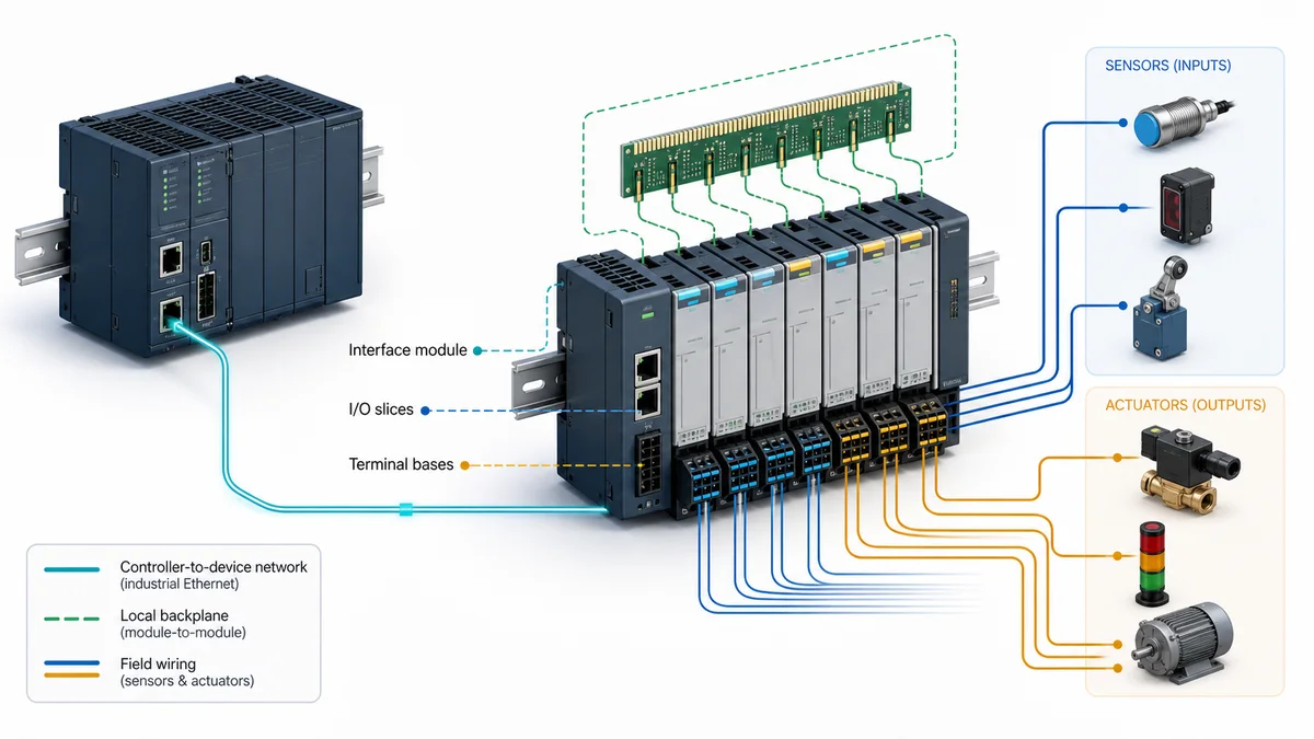
“ET 200” is a product-family label, not one rack specification. ET 200SP, ET 200MP, ET 200AL, ET 200eco PN, ET 200pro, ET 200S, ET 200M, ET 200SP HA and ET 200 CPUs do not share one interface, environmental rating, module limit, redundancy model or engineering path. This page owns the ET 200/ET 200SP product-specific PROFINET implementation task. Use the PROFINET PLC guide for vendor-neutral protocol roles, GSDML, slots/subslots, timing, topology and MRP. Use the PLC remote I/O modules guide to select remote-I/O architecture across vendors. Use the exact current Siemens manual for the installed articles as the final authority.
Choose the correct owner and ET 200 family
| Search or engineering task | Correct content owner | Boundary |
|---|---|---|
| Configure ET 200SP on PROFINET | this guide plus exact Siemens manuals | product-specific interface, rack, BaseUnit, name and diagnostic workflow |
| Learn PROFINET controller/device behavior | PROFINET PLC guide | vendor-neutral protocol model and commissioning principles |
| Compare remote I/O architectures | PLC remote I/O modules guide | controller-independent adapter, power, channel and fault-state selection |
| Configure an S7-1200 controller's PROFINET interface | separate S7-1200 task | controller settings and limits are not ET 200 interface-module settings |
| Configure ET 200SP as a local rack behind an ET 200SP CPU | CPU/system documentation | it is not the same topology as a remote IM 155-6 IO Device |
| Replace ET 200S or ET 200M with ET 200SP | migration project | wiring, addressing, terminals, diagnostics and mechanics require engineered conversion |
Select the family before selecting modules
The current Siemens ET 200 portfolio includes cabinet, machine-mount and process-oriented families. The useful selection question is not “which ET 200 is best?” It is “which documented station architecture meets the environment, channel density, signal types, availability, controller compatibility, safety lifecycle, wiring and maintenance requirements?” Record that decision before copying any sample rack into TIA Portal.
| Family or architecture | Typical design context | Do not transfer blindly |
|---|---|---|
| ET 200SP | compact control-cabinet distributed I/O with slim modules and separate BaseUnits | interface-module capacity, BaseUnit type, potential groups, hot-swap and redundancy support |
| ET 200MP | S7-1500-style high-density modules centrally or behind a supported interface | physical construction, channel modules and interface limits differ from ET 200SP |
| ET 200AL / ET 200eco PN / ET 200pro | machine-level or field-mounted I/O in supported environments | ingress rating, connectors, topology, power and expansion architecture are product-specific |
| ET 200SP HA | process/high-availability-oriented architecture | terminal blocks, availability, redundancy and system integration are not ordinary ET 200SP claims |
| ET 200S / ET 200M | established installed-base systems | lifecycle, spare availability, software support and migration path must be checked for the exact station |
| ET 200SP CPU or Open Controller | distributed controller with local ET 200SP I/O | controller execution, memory, program, security and local-rack behavior replace the simple IO Device model |
Separate the PLC, interface module and I/O modules
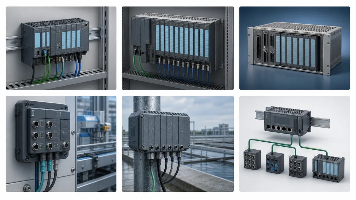
In the normal remote-I/O topology, the PLC owns the PROFINET application relationship and exchanges cyclic data. The ET 200SP interface module terminates PROFINET, manages the local backplane and reports station/module/channel diagnostics. The I/O modules convert field signals and apply their configured parameters. BaseUnits provide terminals and distribute or interrupt power rails. The server module terminates the station. These parts form one station but are not interchangeable roles.
If the leftmost device is an ET 200SP CPU, the local I/O is controlled through that CPU's local architecture; the CPU may also operate as a PROFINET controller or device if its exact model supports the configured role. If the leftmost device is IM 155-6 MF HF, its selected fieldbus personality and configuration tool matter. Do not call every left-hand module an “ET 200 PLC.”
Build an exact compatibility baseline
Capture hardware and software identity from evidence
Create a row for every physical component, beginning with the interface and continuing left-to-right through every module and BaseUnit. Record the full order number, hardware revision, firmware, configured catalog object, configured device version, module position, BaseUnit type, field-supply group and current documentation revision. Photograph labels before installation hides them. Export or screenshot the online identification after power-up.
| Evidence field | Obtain it from | Failure prevented |
|---|---|---|
| interface article and hardware function state | device label and online identification | loading a near-match with different ports, capacity or functions |
| firmware and configured device version | approved online tool and project properties | unsupported feature or replacement-compatibility assumptions |
| I/O module article and slot | label, rack walkdown and project | module-difference fault or shifted process data |
| BaseUnit type and potential-group role | visible BaseUnit marking and module manual | wrong terminals, power rails or new-group/continue-group behavior |
| controller CPU/interface and firmware | label, project and online evidence | unsupported IO Device count, timing, redundancy or diagnostics |
| engineering system and update | installed software evidence | missing catalog entry, HSP/GSD compatibility or compile difference |
| GSDML/GSDX filename and checksum when used | controlled Siemens download and project archive | silent use of an old or untrusted device description |
Product Information can supersede statements in a system or equipment manual. Check Siemens' current ET 200SP Product Information and firmware notices, not just the PDF saved with the original project. A new GSDML is not automatically a reason to update a running plant: review its change history, engineering compatibility and affected modules, then regression-test the approved change.
Choose integrated catalog data or controlled GSDML
TIA Portal can contain an integrated Siemens hardware object for the exact device, or an engineering system can import a supported GSDML/GSDX. The project must use a description that includes the installed interface, firmware representation and I/O modules. The current Siemens ET 200SP GSD support page publishes files, tool-version compatibility and change history; use that controlled source instead of a file from an anonymous archive or forum attachment.
GSDML describes PROFINET device identity, modules, submodules, data sizes, parameters and diagnostics. It is not device firmware. Installing a newer description does not update the rack. Conversely, updating firmware does not guarantee that an old project catalog understands every new function. Preserve the GSD/HSP source, version and checksum with the project so another engineer can reconstruct the configuration.
Design the ET 200SP station before TIA Portal
Make physical and configured module order identical
Start from the interface module and list every position to the server module. For each I/O slice, capture its module article, supported BaseUnit, signal type, channel wiring, parameter set, input/output byte count and diagnostic behavior. The same family can contain modules with similar front markings but different electrical ranges or function classes. Never use color alone as identification.
If option handling is not deliberately configured, an omitted module or an insertion at the beginning can shift every following physical position away from the project. The controller may report a station or module mismatch; the field consequence can be worse if maintenance then edits addresses to hide the mismatch. Correct the hardware/project identity first. Treat all address changes as application changes with a new I/O checkout.
Engineer BaseUnits and potential groups as circuits
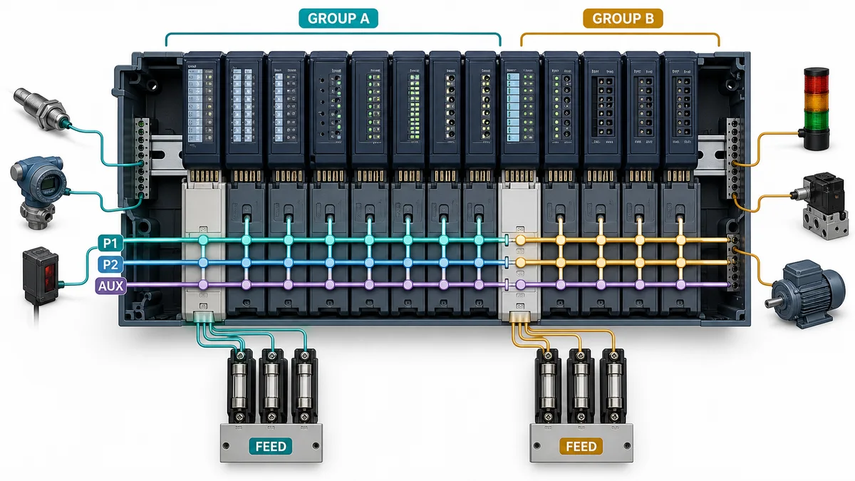
ET 200SP modules plug into BaseUnits that are selected separately. A light-colored feed BaseUnit starts a potential group and interrupts the self-assembling P1, P2 and AUX rails from the group on its left; compatible darker BaseUnits continue the group. The exact module equipment manual defines which BaseUnit types are allowed and what terminals mean. The color convention is a useful field clue, not a substitute for the order number.
| Design item | Required record | Acceptance evidence |
|---|---|---|
| first BaseUnit in each group | exact type, supply source, fuse/protection and conductor IDs | voltage and polarity at documented terminals under expected state |
| continuing BaseUnits | exact compatible types and slot positions | rail continuity only within the intended group |
| P1/P2/AUX use | documented circuit meaning for the selected modules | no unapproved cross-feed between isolated loads or supplies |
| field common/reference | drawing and terminal schedule | measured reference matches input/output circuit design |
| shield/functional earth | module/system manual and EMC design | termination and bonding inspected, not inferred from signal quality |
| output safe/substitute state | module parameter and machine risk assessment | controller stop, communication loss and power-cycle behavior tested |
Budget power, timing and network capacity together
Calculate interface and backplane demand, field-load demand, inrush, temperature derating, voltage drop and group protection from current manuals. Then calculate process latency: sensor conversion/filtering, PROFINET update, controller I/O/task timing, program scan, output update and actuator response. The smallest selectable update time is not the achieved machine response and may add unnecessary network/controller load.
| Timing layer | Design question | Evidence |
|---|---|---|
| field input | what filter/conversion and debounce apply? | module parameters and measured transition timing |
| PROFINET provider | what update and watchdog are configured and supported? | controller/device online configuration |
| PLC application | when does logic consume inputs and publish outputs? | task/scan trace at representative worst load |
| output module | what output delay, substitute behavior or pulse function applies? | exact module manual and controlled test |
| network | does topology, switch load or recovery create tails/loss? | topology record, port counters and packet/diagnostic evidence |
Live mini-lab
Try it: press START, then STOP
A stop-dominant seal-in rung: START latches the motor output through its own contact, and STOP breaks the circuit.
Watch the output lamp: it stays on after START until you press STOP.
Free to start · runs in your browserOpens plcsimulationsoftware.com — same team
Configure ET 200SP PROFINET in TIA Portal
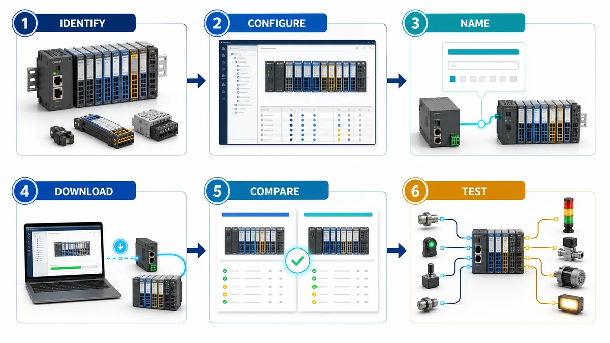
Follow a controlled six-stage workflow
- Open the approved controller project and create a backup/difference record.
- Add the exact ET 200SP interface module or import its controlled Siemens GSDML/GSDX.
- Select the configured device version and add I/O modules in exact physical order, including supported BaseUnit/potential-group settings and channel parameters.
- Connect the station's PROFINET interface to the correct controller interface/subnet and set the planned device name, IP parameters, topology and supported timing.
- Compile hardware and software; resolve device, slot, address, parameter, safety and resource messages rather than suppressing them.
- In an approved window, assign the device name to the verified physical MAC, download the controller configuration, compare online/actual hardware and perform the acceptance matrix.
Assign the PROFINET name to the intended physical device
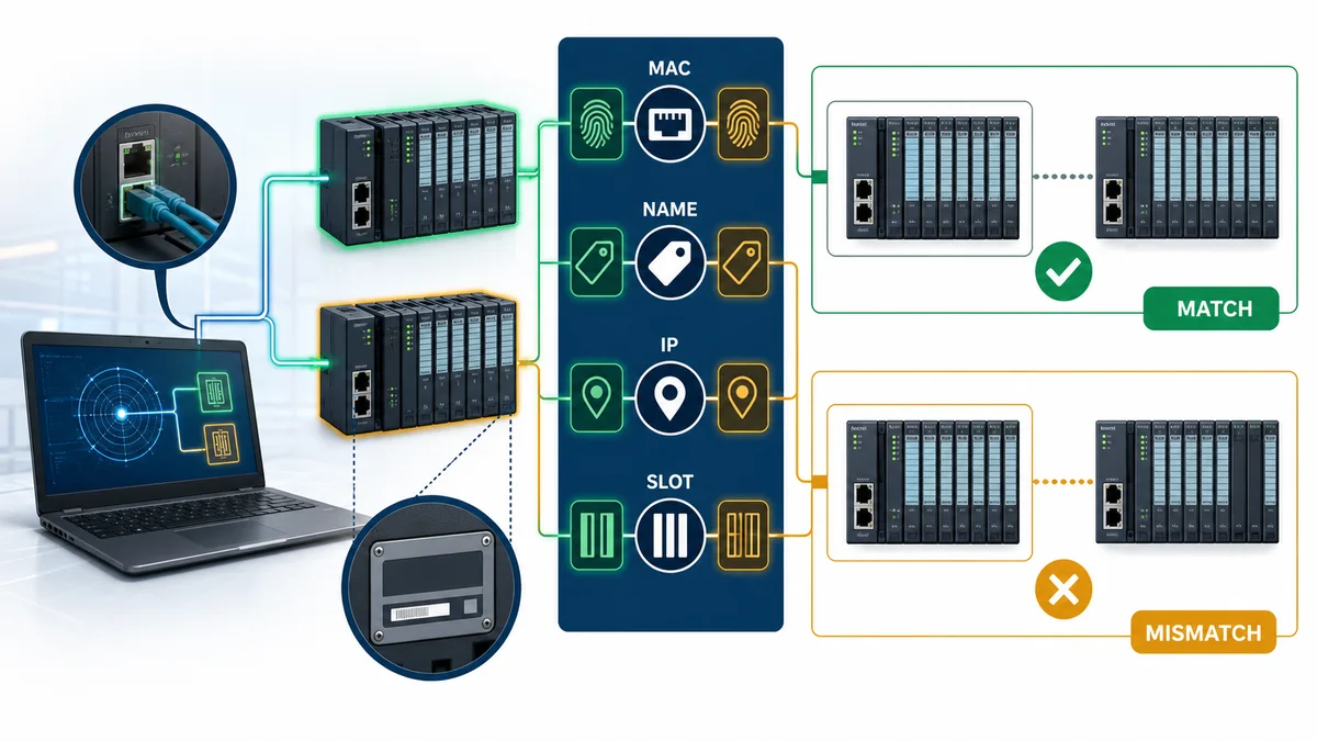
The project gives the IO Device a configured PROFINET station name. During first commissioning, an engineering tool discovers accessible devices on the local network and uses MAC identity/flash or other physical correlation to select the intended rack. Assign the exact planned name, read it back, and verify that the controller associates it with the correct configured station. Use naming rules supported by the engineering system and network design.
IP reachability is secondary evidence. Depending on the configured behavior, the controller can apply IP parameters after identifying the device by name. DCP discovery/name assignment is normally a local Layer-2 operation, so do not expect it to cross a routed boundary like an ordinary IP request. If remote engineering is authorized, use an approved architecture rather than flattening production networks simply to make discovery visible.
Compile and download without hiding mismatches
Compile proves that the engineering tool accepts the selected controller, interface, modules, addresses and parameters. Download changes the controller's expected configuration. Neither proves the field rack matches. After download, use online diagnostics and accessible-device evidence to compare expected and actual article, firmware, device name, module order and parameter state.
Do not rename the wrong physical rack to clear a red icon. Do not substitute a similar module in the project merely because its byte count matches. Do not force outputs to make a machine run before identity and safety checks are complete. If a device-version conversion is required, preserve the original project, review the conversion report and regression-test every affected function.
Map slots, subslots and PLC tags deliberately
Build an I/O map from project to terminal
PROFINET represents modular devices with slots and subslots. TIA Portal maps the configured process data into PLC addresses or tags. Your commissioning record must connect four layers: project device/slot/subslot, PLC tag/address, physical module/channel/terminal and field instrument or actuator. A readable tag does not prove the wire lands on the intended terminal; a channel LED does not prove the program uses the intended bit.
| Mapping layer | Example record | Verification |
|---|---|---|
| station | configured name, interface article, cabinet/location | label, MAC/name readback and project |
| slot/subslot | module article, position and direction | online expected/actual module comparison |
| process data | PLC tag, byte/bit or word, data type and status | watch table with controlled stimulus |
| terminal | BaseUnit terminal and conductor ID | drawing-to-terminal inspection |
| field | instrument tag, range, normal state and fail state | calibrated stimulus or controlled actuation |
| application | interlock, alarm, scaling and output permission | scan-aware functional acceptance test |
Preserve value status and diagnostics where designed
Some supported ET 200SP modules/configurations provide value status or channel diagnostics in addition to the process value. A program that uses only the numeric value can mistake a substituted, invalid or stale signal for a valid measurement. Map quality/status into the application where the process risk and exact module capability require it. Define how a channel fault, module removal, station loss and controller stop affect commands, alarms and retained values.
Diagnostics are not uniform across all modules. Enable only supported diagnostics that the electrical design can interpret. For example, a wire-break diagnostic depends on signal type, module capability, parameterization and field circuit. An unwanted open contact on an ordinary digital input is not automatically distinguishable from a legitimate off state.
Commission the station safely
Complete pre-power and pre-output gates
Follow the site's electrical safety, lockout/tagout, arc-flash, functional-safety and commissioning procedures. Before energizing, inspect part numbers, orientation, coding elements, BaseUnits, potential-group feeds, protective devices, grounding/bonding, network connections and field wiring. Confirm that output energy cannot cause unexpected movement or process release. A software force is not an isolation method.
Siemens' commissioning sequence places installation, wiring and protective checks before controller/device energization, configuration download, LED review and I/O testing. Adapt that sequence to the machine risk assessment. For safety I/O or PROFIsafe, use the certified lifecycle, F-address and validation procedure for the exact products; this generic guide cannot validate a safety function.
Run positive, negative and recovery tests
| Test | Expected evidence | Negative or recovery case |
|---|---|---|
| identity | exact physical rack receives the planned device name | similarly named adjacent device remains unchanged |
| controller relationship | station enters expected data exchange with valid status | wrong/blank name remains diagnosed rather than silently adopted |
| module match | every configured module/submodule matches actual | remove or substitute one approved test module and observe precise diagnosis |
| digital input | controlled contact changes the exact tag and application state | open/short or field-supply loss produces designed state/diagnosis |
| analog input | calibrated low/mid/high points map to correct units/status | underrange, overrange or wire break follows documented behavior |
| digital output | permitted command drives the exact terminal/load | interlock, stop, station loss and power cycle produce safe designed state |
| analog output | commanded points match measured loop response | loss of controller/device follows configured substitute behavior |
| network recovery | approved link interruption is detected and recovers as specified | duplicate name/IP or wrong topology remains diagnosable |
| replacement | authorized replacement can be identified, named and restored | wrong article/firmware/GSD is rejected or produces a clear hold point |
Troubleshoot ET 200 PROFINET faults by evidence layer
Use the six-layer diagnostic order
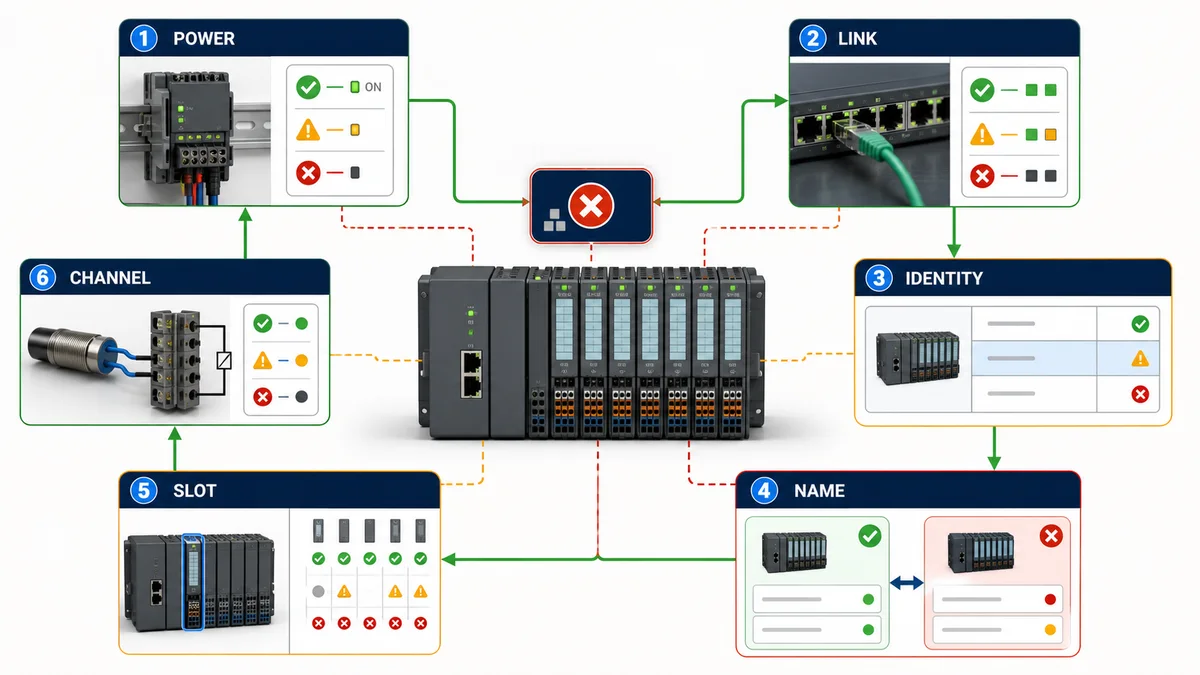
Start with power, then physical link, discovered identity, configured name/IP, device/module configuration and finally channel/field behavior. This order prevents a green channel LED from distracting you from a missing application relationship, and prevents a successful ping from being treated as valid I/O.
Read the symptom-to-evidence matrix
| Symptom | Highest-value evidence | Likely boundary | Avoid first |
|---|---|---|---|
| entire station absent | interface supply, LEDs, switch port, accessible devices | power, media or wrong network path | editing every module parameter |
| link and ping work, no cyclic I/O | controller device diagnostic, configured/actual name and AR state | PROFINET identity/configuration | replacing Ethernet cable repeatedly |
| station present, module fault | expected/actual slot article and parameter diagnosis | module order, wrong article, missing module or unsupported version | shifting PLC addresses to match accident |
| one potential group dead | voltage at documented feed, fuse and BaseUnit boundary | field supply or group design | renaming the station |
| one channel wrong | terminal measurement, channel LED/diagnosis, tag map | wiring, parameter, scaling or application | replacing interface module |
| intermittent loss | switch counters, topology, event timestamps, supply trace | media, connector, power, load or recovery timing | assuming average ping proves stability |
| replacement will not start | article/firmware, configured device version, name and GSD/HSP | compatibility and identity | factory-resetting unrelated devices |
| output remains active after loss | module substitute behavior and application/safety design | configured fault reaction | treating communications repair as risk control |
LEDs narrow a fault only when interpreted with the exact interface/module equipment manual. Preserve which LEDs were on, off or flashing, their colors and timing. “Red light” is not a diagnostic record. Pair LED evidence with the controller diagnostic buffer, online module status, switch evidence and electrical measurements.
Replace a failed interface without creating a second fault
Before replacement, preserve the failed unit's article, hardware/firmware, device name, IP behavior, removable media if applicable, configuration and diagnostics. Verify the replacement's documented compatibility and whether device replacement without a programming device/topological support is configured and supported. Use the controlled procedure for name assignment, firmware alignment and project download.
After replacement, repeat identity, module comparison, I/O status, substitute-state and recovery tests. A station returning to green is not proof that the field terminals, scaling, output behavior or alarms remain correct. If a different interface variant is substituted, treat it as a design change even if it accepts the same I/O slices.
Use advanced functions only when the exact combination supports them
Qualify redundancy, shared device and isochronous behavior
Capabilities such as MRP, shared device, MSI/MSO, isochronous operation, prioritized startup, system redundancy, PROFIenergy, device replacement and multi-hot-swap vary by interface article, firmware, controller, engineering version, modules and topology. The presence of a menu item or a feature on one IM 155-6 variant does not establish support on another.
Create a compatibility row for every advanced function: controller support, interface support, I/O-module support, switch/topology requirement, firmware, TIA/GSD version, limit, failure behavior and tested recovery. For redundancy, distinguish media path recovery from controller redundancy, device/interface redundancy, I/O redundancy and functional safety. MRP does not make an ordinary single interface or single field circuit redundant.
Separate option handling and MultiFieldbus paths
ET 200SP configuration control lets a documented station master support defined physical station options by transferring a control data record. It is not permission to plug modules in arbitrary positions. The project, user program, station option and feedback record must agree, and the resulting mapping must be acceptance-tested.
An IM 155-6 MF variant can support multiple industrial Ethernet personalities as documented, but it does not communicate on all protocols automatically. Select the fieldbus personality and use the prescribed configuration path, such as MFCT where applicable. A Modbus TCP or EtherNet/IP mapping produced for a MultiFieldbus controller is a separate contract from the PROFINET slot/subslot mapping owned by this guide.
Create a handover-grade acceptance record
Keep one evidence pack per station
The minimum pack should include the approved project version, station name, controller/interface identity, rack and BaseUnit bill of materials, firmware, engineering version, GSD/HSP source, IP/subnet/VLAN, topology/ports, update/watchdog settings, I/O map, power-group drawing, diagnostic configuration, safe/substitute states, test results, unresolved deviations and backups. Add photographs that allow a maintainer to correlate project slot with physical module and terminal.
Record measured results, not “checked OK.” For example: “Configured station rack-03 assigned to verified MAC ending 7C:21; controller showed data exchange; slot 5 article matched; calibrated 12.000 mA produced 50.01% and Good status; opening the loop produced the documented channel diagnostic within the measured interval.” Mask sensitive addressing when publishing externally, but keep the protected plant record complete.
Define completion by behavior
Commissioning is complete when configuration identity, cyclic data, diagnostics, application behavior and recovery meet the approved specification under representative conditions. It is not complete because the rack is green, because TIA compiled, because a ping worked or because one input changed in a watch table.
Use the industrial communication training path to rehearse controller/device roles, layered diagnosis, I/O mapping and fault isolation before touching a plant network. The browser simulator cannot certify an ET 200 article, BaseUnit, firmware, GSDML, electrical circuit, timing, topology, safety behavior or Siemens project. Verify those in the approved engineering environment with current manuals and controlled plant tests.
Diagnostic answer map
| Natural-language query | Concise answer | Evidence to capture |
|---|---|---|
| How do I configure ET 200SP on PROFINET? | Add the exact interface and module order, connect it to the controller network, assign the configured name to the verified physical device, download and compare online hardware before I/O tests. | article/firmware, project, name/MAC, module comparison and acceptance matrix |
| Why is ET 200SP reachable but not connected? | IP reachability does not prove the configured PROFINET name, identity, modules or application relationship match. | controller PNIO diagnosis, configured/actual name, interface and slots |
| Why does ET 200SP show a module difference? | The expected slot/subslot or device version differs from the actual module, order or supported description. | exact article per slot, online comparison, GSD/HSP and firmware |
| How do I assign an ET 200 PROFINET name? | Discover locally, correlate the target by MAC/physical flash or label, write the exact configured name and read it back. | before/after accessible-device record and physical identity |
| Why is one ET 200SP group unpowered? | A potential-group feed, fuse, BaseUnit or common may be missing even while the interface/backplane remains online. | voltage measurements at documented terminals and group drawing |
| Can I replace an IM 155-6 with another variant? | Only after documented article/firmware/module compatibility and a full regression test; similar appearance is insufficient. | compatibility manual, project conversion and I/O/recovery tests |
| Does a green ET 200SP rack prove good I/O? | No. It does not prove terminal mapping, scaling, quality, interlocks, substitute state or field behavior. | channel-by-channel positive, negative and recovery results |
| Do I need GSDML for ET 200SP in TIA Portal? | Use an integrated catalog object when it exactly supports the device, otherwise a Siemens-supported GSDML/GSDX compatible with the tool and hardware. | catalog/GSD version, source, checksum and compile report |
| Is ET 200SP a PLC? | ET 200SP can be remote I/O behind an interface or a distributed controller when built around an ET 200SP CPU; identify the leftmost device and role. | exact article and controller/device architecture |
| Can a simulator validate ET 200 PROFINET hardware? | No. It can train the reasoning path but cannot certify installed Siemens hardware, wiring, firmware, timing or safety. | approved project, manuals, instruments and plant acceptance tests |
Frequently asked questions
What is ET 200 PROFINET?
It is a Siemens distributed-I/O architecture in which a PROFINET-capable ET 200 interface or supported controller exchanges configured data and diagnostics with a PROFINET IO Controller. “ET 200” covers multiple families, so the exact station architecture must be named.
How do I connect ET 200SP to a PLC over PROFINET?
Use a compatible PROFINET IO Controller and the exact ET 200SP PROFINET interface, build the physical and configured racks identically, connect the approved industrial network, assign the configured device name to the intended unit, download the controller project and validate cyclic I/O.
Does ET 200SP need an IP address and a PROFINET device name?
PROFINET commissioning uses the configured device name as the stable project identity, while IP parameters support applicable network services and are managed according to the controller/project design. A correct IP alone does not establish cyclic I/O.
Why can I ping ET 200SP but still have an IO fault?
Ping proves a limited IP path. The interface article, configured name, device version, module/submodule order, parameters and PROFINET application relationship can still be wrong. Read the controller's native PROFINET and module diagnostics.
Do I need a GSDML file for ET 200SP?
Not always. An exact integrated TIA Portal catalog entry may be appropriate. If the device or module is not supported there, use only the current compatible Siemens GSDML/GSDX or prescribed support package and preserve its version and source.
What causes an ET 200SP module difference fault?
A configured slot can differ from the actual article, order, device version or supported module description. Missing modules, wrong placement and unconfigured option handling also cause mismatches. Compare expected and actual hardware rather than shifting addresses.
What is an ET 200SP BaseUnit potential group?
It is a set of adjacent modules sharing documented P1, P2 and AUX supply rails. A compatible light-colored feed BaseUnit starts a group and interrupts the rails from the left; compatible darker BaseUnits continue it. Verify exact articles and wiring manuals.
Can I hot-swap ET 200SP modules while the station is running?
Only if the exact interface, module, BaseUnit, firmware, configuration, electrical circuit and site procedure support the documented operation. Hot-swap capability does not remove electrical, process or functional-safety hazards.
Can ET 200SP use PROFIsafe over PROFINET?
Supported fail-safe ET 200SP modules can participate in a validated PROFIsafe system when used with compatible certified controllers, interfaces, parameters and lifecycle controls. Ordinary PROFINET configuration or a standard I/O test does not validate a safety function.
How should ET 200SP PROFINET be acceptance-tested?
Verify identity, configured-versus-actual modules, potential groups, cyclic status, every channel and terminal, scaling, diagnostics, safe/substitute states, link loss, power cycle and approved replacement/recovery behavior. Save measured results with the project baseline.
Sources, review scope, and limitations
This guide was reviewed on August 30, 2026 against the following direct first-party or standards-body sources. Siemens documentation is modular and Product Information can supersede manuals. Exact article numbers, hardware revisions, firmware, tool updates, BaseUnits, modules, environmental ratings, limits and supported functions must be verified for the installed station. The illustrations are original conceptual training graphics, not Siemens product renders, terminal diagrams or proof of compatibility.
- ET 200SP Distributed I/O System Manual, 11/2025 — Siemens — system planning, installation, wiring, configuration, commissioning, maintenance and test context.
- ET 200SP Manual Collection V21 — Siemens — current modular product documentation and module-specific behavior.
- ET 200SP as a PROFINET IO Device — Siemens — documented installation-to-I/O-test commissioning sequence.
- PROFINET with STEP 7 Function Manual, 11/2025 — Siemens — controller/device configuration, naming, diagnostics, topology and PROFINET functions.
- IM 155-6 PN ST Equipment Manual — Siemens — interface-specific functions, wiring, diagnostics and compatibility boundaries.
- IM 155-6 MF HF Equipment Manual — Siemens — MultiFieldbus interface role, compatibility and configuration boundary.
- PROFINET GSD files for ET 200SP — Siemens — controlled GSDML/GSDX downloads, tool compatibility and change history.
- ET 200SP Product Information — Siemens — updates that can take precedence over manuals.
- ET 200SP firmware collection — Siemens — controlled firmware source and lifecycle evidence.
- SIMATIC ET 200 portfolio — Siemens — current family and application-positioning boundary.
- SIMATIC ET 200SP product overview — Siemens — current product-family overview and selection context.
- PROFINET technology overview — PROFIBUS & PROFINET International — official IO Controller, IO Device, cyclic data and ecosystem context.
- PROFINET Commissioning Guideline — PI — identity, network and commissioning practices.
- NIST SP 800-82 Rev. 3 — OT segmentation, access, change and monitoring security context.
Now run it · free to start
Follow plant data from sensor to SCADA
Fieldbus versus Ethernet, Modbus, EtherNet/IP, PROFINET, OPC UA and MQTT, then SCADA layers and alarms, taught on simulated equipment. Free to start.
Ownership disclosure: PLC Programming IO and PLC Simulation Software are operated by the same publisher.
PLC Programming IO Editorial Team
Industrial automation education, references, and software testing
The PLC Programming IO Editorial Team publishes sourced industrial-automation education and documents how material is reviewed, tested, and corrected. A team byline means the publisher is responsible for the page; it does not represent a fictional person or imply an engineering licence.
Coverage:
- • PLC programming concepts and examples
- • Vendor software tutorials and comparisons
- • SCADA, HMI, protocols, and instrumentation
- • Training, careers, and reference material
Review standard:
- • Prefer primary and official sources
- • Record software versions when material
- • Separate tested facts from estimates
- • Publish material corrections
Important scope note
This site provides education, not project-specific engineering approval. Safety, code, and compliance decisions require a qualified person with access to the actual machine and jurisdiction.