PLC Tester: Choose Tools and Test I/O Safely
Choose the right PLC tester for digital, analog, pulse, logic, network or HIL faults, then run ordered checks with expected readings and safe restoration.
Review status: Editorially reviewed against current manufacturer documentation for PLC Tools signal/pulse simulators, Fluke 4–20 mA loop calibration and PLC measurement practices, Siemens TIA Portal Test Suite V20 and S7-PLCSIM Advanced, Siemens SIMIT hardware/software-in-the-loop scope, Rockwell FactoryTalk Logix Echo and its October 2025 Getting Results Guide, Speedgoat/MathWorks PLC HIL material, NIST SP 800-82 Rev. 3, and US OSHA hazardous-energy/electrical work rules. Tester category, ratings, signal mode, isolation, I/O thresholds, wiring, source/sink behavior, sampling, scan/task timing, emulator coverage, safety behavior, network access, acceptance limits and authorized work remain exact-PLC-, module-, tool-, firmware-, project-, process-, risk- and site-specific
Direct answer
A PLC tester is any controlled tool or test system that stimulates one PLC boundary and independently observes the next. It may be a switch box for 24 VDC inputs, a loop calibrator for 4–20 mA channels, a pulse/encoder or RTD simulator, a meter or protocol analyzer, PLC emulation software, or a hardware-in-the-loop (HIL) rig. There is no single tester that safely proves field wiring, I/O electronics, program logic, communications and process response at once.
Choose the tester from the failed boundary. If a physical input never reaches the input image, measure the field signal and use an electrically compatible input simulator only under an approved test. If raw analog counts are wrong, inject known points and compare terminal current, module raw value and engineering scale. If the I/O image is correct but the sequence is wrong, use a trace, emulator or automated test harness. If the logic passes but the machine interaction fails, add a process model or HIL system.
A credible PLC test has six records: known initial state, controlled stimulus, expected PLC state, expected output, independently measured process response and safe restoration. “The light changed” is not enough. Record exact tool/model/settings, connection point, expected range/tolerance, actual reading, timestamp, PLC project/firmware, result and evidence link.
Never discover an output address by forcing or energizing it on operating equipment. Separate software simulation from physical proof, standard logic from safety validation and a browser exercise from an exact controller. Use the PLC troubleshooting simulator to practise ordered evidence collection, then transfer the method only through an approved site test plan.
This page owns tester selection and test execution. Use the intermittent PLC fault guide when the fault is sporadic and environmental, the PLC input and output troubleshooting guide for deeper channel diagnosis, and the PLC program debugging guide for code-writer/state analysis.
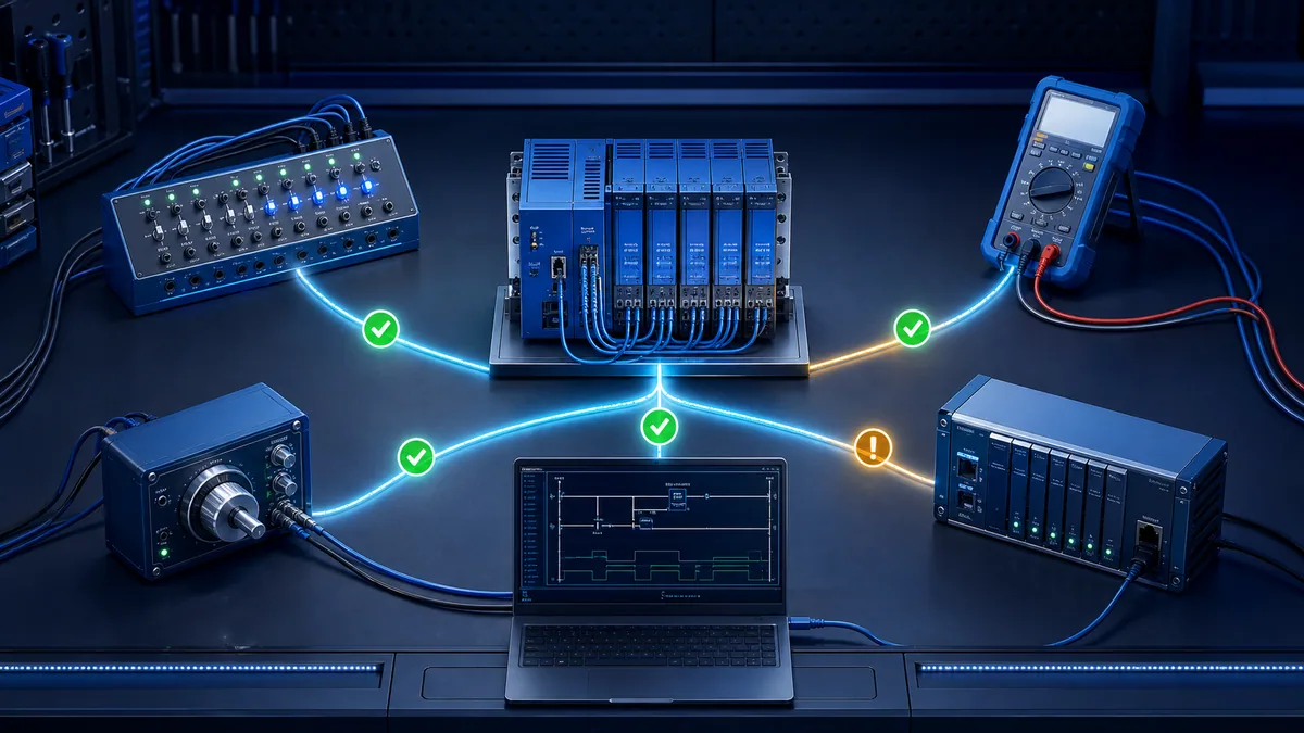
Choose the tester by evidence boundary
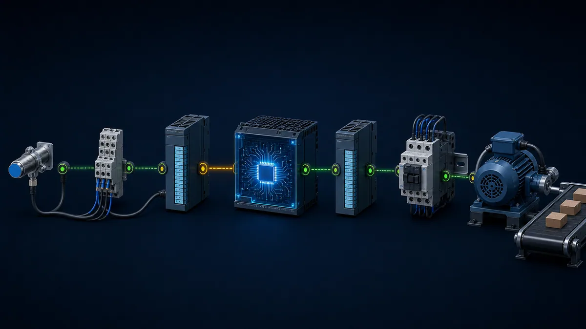
Map the complete signal path before selecting a tool
Draw the path from process condition to sensor, cable/terminal, input electronics, PLC input image, logic/state, output image, output electronics, starter/drive/valve and physical response. Put an observable test point between every pair. A useful tester can control or measure one of those points without creating an uncontrolled second path.
For example, a laptop changing a simulated input tag can test logic but not a field wire or input threshold. A 24 V switch box can test an input channel but not prove the sensor. A meter at the output terminal can show voltage but not prove current under load or mechanical movement. HIL can exercise timing and sequences but only within its modeled fidelity and interface coverage.
| Suspected boundary | Primary tester class | Stimulus | Independent observation | What it cannot prove alone |
|---|---|---|---|---|
| Field sensor to terminal | Meter/process calibrator | Known process or simulated sensor | Terminal voltage/current/resistance | PLC logic and process output |
| Terminal to digital input image | Rated digital signal simulator | Known OFF/ON electrical state | Terminal reading plus PLC raw input | Sensor health or actuator behavior |
| Analog loop to raw input | Loop calibrator and meter | Known current/voltage points | Measured loop plus raw counts | Scaling logic beyond selected points |
| Pulse/encoder to high-speed count | Compatible pulse simulator/scope | Frequency/direction pattern | Input status/count/trace | Real encoder mechanics and EMC environment |
| PLC logic/state | Emulator, trace or test harness | Defined tag/state sequence | Expected state/output/timing | Real I/O thresholds and field loads |
| PLC communications | Protocol-aware client/analyzer | Known request/message/state | Capture, diagnostics and consumer quality | Physical process response |
| Controller plus plant interaction | HIL/process model | Closed-loop scenario/fault | PLC, model and timing evidence | Unmodeled mechanics/environment |
| Final machine response | Approved functional test | Safe commanded scenario | Independent physical/process measurement | Every hidden failure unless coverage is defined |
Do not confuse a tester, trainer, simulator and monitor
A tester executes a defined check and produces pass/fail evidence. A trainer teaches skills, often on simplified hardware. A simulator reproduces selected signals or behavior. An emulator executes a controller-like runtime for a supported controller family. A monitor observes without necessarily stimulating. One product may combine roles, but the test plan must state which capability is being relied on.
| Term | Primary purpose | Typical example | Required limitation statement |
|---|---|---|---|
| Meter/monitor | Observe electrical or protocol state | DMM, scope, packet capture | Observation point and loading/bandwidth |
| Signal simulator | Generate a controlled electrical input | 24 V switch box, 4–20 mA or pulse source | Output mode, rating, isolation and fidelity |
| PLC simulator | Execute selected PLC/program behavior | Browser lab or vendor simulation mode | Supported instructions, timing, I/O and communications |
| PLC emulator | Reproduce supported controller runtime | PLCSIM Advanced or Logix Echo | Exact supported controller/firmware/features |
| HIL system | Close real controller around a real-time plant model | Real PLC plus deterministic I/O/model | Model/interface fidelity and timing bounds |
| Test framework | Arrange stimuli and assert outcomes | Vendor test suite or custom harness | Interface sampling, determinism and oracle quality |
| Trainer | Develop operator/technician skill | Bench panel with exercises | Not production acceptance evidence by itself |
Test digital PLC inputs with a controlled source
Confirm input type, common and threshold before connection
Read the exact input module manual and approved schematic. Identify nominal voltage, AC/DC type, source/sink convention, input common grouping, ON/OFF thresholds, input current, filter/debounce, isolation, leakage constraints and terminal assignment. A generic “24 V PLC tester” can damage a different input or create a short if its reference/common and output mode are misunderstood.
Isolate the field device from the test source according to the approved method so two supplies cannot oppose each other. Verify the tester output with a suitable meter before landing it. Use current-limited/fused low-voltage test power where the design permits. Apply OFF, then ON, then OFF; compare terminal voltage, module indicator, raw input image, filtered application tag and downstream state. Record response and release time rather than only final state.
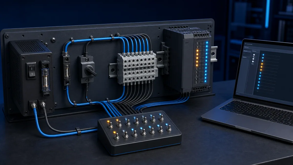
Use an input truth table with expected readings
The readings below are a template, not universal voltage limits. Replace them with the exact module's published thresholds and the approved circuit values.
| Test state | Tester output | Expected terminal measurement | Module/raw input | Application expectation | Fail interpretation |
|---|---|---|---|---|---|
| Isolated baseline | Tester disconnected | Circuit-specific safe baseline | OFF | Safe/idle | Unexpected energy or backfeed |
| Commanded OFF | Valid OFF state | Below exact OFF threshold | OFF | No transition | Leakage/reference/wiring/filter issue |
| Commanded ON | Valid ON state | Above exact ON threshold under load | ON | Expected state starts | Open circuit, wrong common, channel fault |
| Held ON | Stable valid signal | Stable without excessive drop | Remains ON | Timer/sequence advances as specified | Intermittent terminal, supply or scan/filter issue |
| Returned OFF | Valid OFF state | Falls below OFF threshold | Returns OFF | Sequence stops/resets per design | Stuck input, leakage, filter or program latch |
| Adjacent channel check | Only selected point ON | Other points remain in their states | No crosstalk | No unrelated transition | Common/terminal/map or tester harness error |
Digital output testing is different. Begin by observing PLC output image, module indicator and terminal/load state under a safe authorized command. Do not use a source-type input tester on an energized output. For a removed/de-energized module, use the manufacturer's approved bench procedure. For installed machinery, the test plan must control energy, interlocks and process consequences.
Test analog inputs without confusing source, simulate and measure modes
Select the correct loop-calibrator mode
A loop calibrator may source current using its own supply, simulate a two-wire transmitter while the loop supplies power, measure current in series, or provide loop power to an isolated transmitter. These modes are not interchangeable. Fluke's current guidance explicitly separates powering/measuring an offline transmitter from simulating a transmitter into a powered loop.
Before connection, record whether the PLC channel is active or passive, whether loop power already exists, the current/voltage range, polarity, input resistance/burden, isolation, HART resistor or barrier/isolator, hazardous-area boundary and whether opening the loop affects control. Use the exact module/calibrator manuals. An incorrectly powered loop can damage equipment or invalidate a safety/process function.
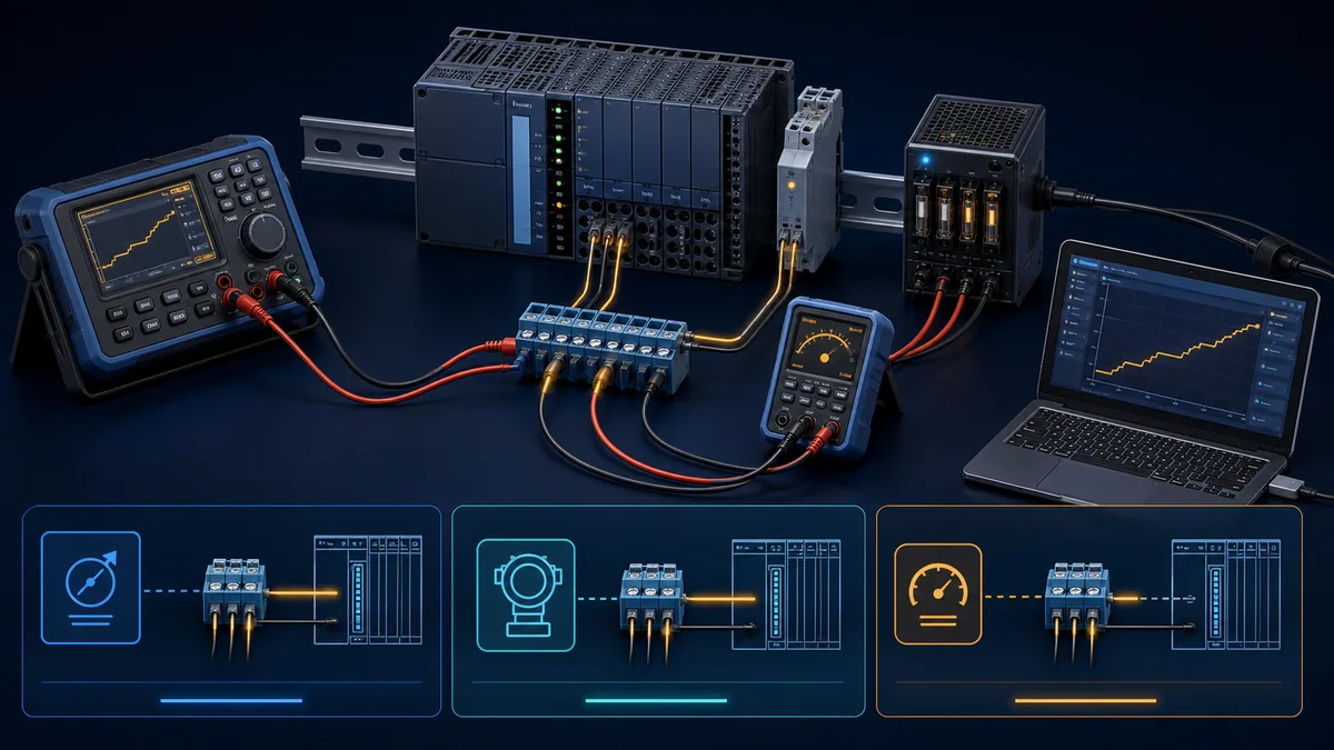
Prove raw counts, scaling, alarming and failure behavior separately
For a nominal 4–20 mA input, use at least 0%, 25%, 50%, 75% and 100% points plus approved underrange/overrange/fault cases. At each point record actual current, raw module value, scaled engineering value, displayed value, quality and alarm/interlock state. Approach points upward and downward when hysteresis or filtering matters. Allow defined settling time, not an arbitrary pause.
| Injection point | Nominal 4–20 mA value | Raw expectation | Scaled expectation | Additional proof |
|---|---|---|---|---|
| 0% | 4 mA | Exact module low raw target/tolerance | Engineering low endpoint | Low-low alarm policy and no false bad-quality |
| 25% | 8 mA | One-quarter span | One-quarter engineering span | Linear interpolation |
| 50% | 12 mA | Mid-span | Mid engineering value | Rounding and display agreement |
| 75% | 16 mA | Three-quarter span | Three-quarter engineering span | Trend monotonicity |
| 100% | 20 mA | Exact module high raw target/tolerance | Engineering high endpoint | High/high-high alarm policy |
| Approved low fault | Module/project-specific | Diagnostic/under-range behavior | Bad/low quality or designed response | Stale-value and fallback behavior |
| Open loop | 0 mA where circuit safely opened | Module diagnostic behavior | Bad quality/alarm | Restoration and event timestamp |
Do not use the nominal current itself as the acceptance tolerance. Combine calibrator accuracy, measurement uncertainty, module accuracy/resolution, signal conditioning, scaling and process requirement. State the allowed error at each layer. A correct HMI value can hide compensating errors; preserve both injected and raw values.
Live mini-lab
Try it: press START, then STOP
A stop-dominant seal-in rung: START latches the motor output through its own contact, and STOP breaks the circuit.
Watch the output lamp: it stays on after START until you press STOP.
Free to start · runs in your browserOpens plcsimulationsoftware.com — same team
Test pulse, encoder, RTD and specialized inputs with compatible simulators
Match electrical interface before frequency or value
Pulse and encoder testers must match voltage level, single-ended/differential or open-collector interface, sourcing/sinking behavior, channel count, A/B phase, index, frequency/duty, load and isolation. An A/B quadrature simulator can prove high-speed input configuration, direction logic and count behavior without spinning a motor, but it cannot prove encoder mechanics, cable shielding under machine noise or coupling alignment.
RTD and thermocouple simulators must match sensor type, resistance/temperature standard, lead configuration, compensation and module configuration. A simple resistance box may test an RTD channel but cannot reproduce every lead-wire or transmitter diagnostic. For each specialized signal, list exactly which behavior the simulator includes and excludes.
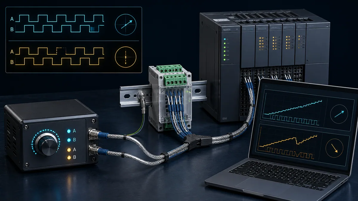
| Specialized input | Tester capability to verify | Minimum cases | Independent observation | Important exclusion |
|---|---|---|---|---|
| Single pulse/high-speed counter | Compatible level and frequency source | Zero, low, nominal, high within rated range, missing pulse | Scope/analyzer plus PLC count/time | Real sensor amplitude/noise/mechanics |
| Quadrature encoder | A/B phase and direction | Forward, reverse, stop, index if supported, channel loss | Trace plus count/direction | Shaft dynamics and installation |
| RTD | Precision resistance or named RTD simulation | Low/mid/high plus lead/open fault if supported | Calibrator value plus raw/scaled PLC | Actual probe thermal response |
| Thermocouple | Correct thermocouple simulation/compensation | Low/mid/high and open diagnostic | Source value plus module diagnostics | Installation junction/EMF environment |
| 0–10 V analog | Rated voltage source and high-impedance observer | Endpoints, midpoint, faults as approved | Terminal voltage plus raw value | Load/common-mode beyond tester |
| Servo command/feedback | Compatible analog/pulse simulator | Direction, speed/frequency, limit and fault cases | Controller trace plus simulator state | Real drive/motor/safety mechanics |
Use software PLC testers for repeatable logic checks
Treat emulation coverage as a versioned test dependency
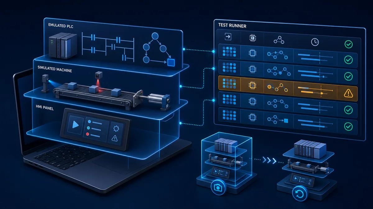
Vendor emulators can execute supported controller projects without physical hardware, but support is exact-product and version dependent. Siemens documents S7-PLCSIM Advanced controller families and simulation capabilities. Rockwell's current Logix Echo page and Getting Results Guide document supported controllers, snapshots and API access. Neither should be described as a universal emulator for all PLC families, legacy modules, communications or hardware effects.
Freeze the emulator version, emulated controller catalog/firmware, project checksum, test model, initial snapshot and known limitations. Verify task scheduling, instruction coverage, motion/safety behavior, communications and externally connected models against current vendor documentation. A test that silently skips an unsupported instruction is not evidence.
Write arrange-act-wait-assert-restore cases
Siemens' current Test Suite documentation uses assignments, waits and assertions for PLC test cases and supports software- and hardware-in-loop contexts. Apply the same test logic even when another platform or manual worksheet is used:
- Arrange exact initial state, inputs, time sources, recipe, mode and fault flags.
- Act with one controlled event or defined event sequence.
- Wait on a bounded condition or justified time, accounting for scan/task and interface sampling.
- Assert state, outputs, diagnostics, timing and invariants—not only the final bit.
- Restore the clean snapshot/state and prove no test residue remains.
| Test-case field | Example content | Why it matters |
|---|---|---|
| Requirement ID | Conveyor start permissive and stop priority | Links evidence to intended behavior |
| Runtime/scope | Exact emulator/PLC and project build | Makes result reproducible |
| Initial state | Stopped, safe, no latched fault, sensors clear | Prevents hidden state dependence |
| Stimulus | Start edge, then product sensor sequence | Defines what changed and order |
| Bounded wait | State reaches RUN within specified range | Prevents arbitrary sleeps/hangs |
| Assertions | State, motor request, timer, alarm, unrelated outputs | Tests outputs and invariants |
| Negative case | Start with permissive absent | Proves rejection path |
| Recovery | Fault clears only after reset policy | Proves restart behavior |
| Evidence | Trace, result file, checksum and timestamp | Supports review and regression |
Add hardware-in-the-loop when timing and plant interaction matter
Know what HIL adds over a signal box
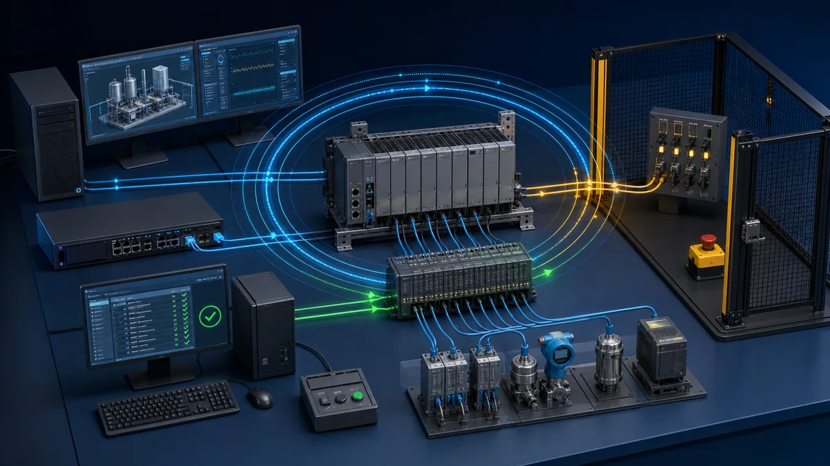
HIL connects a real controller (or controller runtime) to a real-time model and deterministic I/O/network interfaces. It can close loops, generate coordinated sensors, simulate actuator/process dynamics and inject repeatable faults. Siemens describes SIMIT hardware- and software-in-loop use; Speedgoat/MathWorks material shows PLC algorithms running against real-time equipment simulations.
HIL is justified when scan/task timing, multiple interacting devices, closed-loop dynamics, communications, recovery or high-volume regression cannot be represented credibly by manual switches. It is not automatically “more accurate.” Its value depends on I/O/interface fidelity, timing synchronization, plant model validity, fault model, calibration, test oracle and change control.
Validate the model and tester before trusting failures or passes
Run tester self-checks and known-reference cases. Compare model outputs with calculations, design data and measured healthy-machine behavior across the intended operating envelope. Inject one known fault and prove the test catches it; remove the fault and prove it passes. Track requirements-to-tests and unmodeled behaviors.
| HIL assurance item | Evidence | Failure if omitted |
|---|---|---|
| Timing budget | PLC task, I/O update, model step, network and capture timing | False timing pass or failure |
| Interface calibration | Stimulated/measured channels against traceable references | Compensating analog errors |
| Plant-model validation | Comparison to trusted calculations/field data | Unrealistic dynamics |
| Fault-model review | Defined location, onset, duration and physical plausibility | Testing an impossible fault |
| Initial-state control | Snapshot/reset and verification | Order-dependent flaky tests |
| Oracle independence | Expected outcome derived from requirement/model not copied code | Same defect in implementation and test |
| Mutation/known-defect check | Deliberate defect is detected | Test suite appears green but is insensitive |
| Coverage/gaps | Requirements, states, boundaries and exclusions | Overclaiming completeness |
| Release evidence | Versions, checksums, results, anomalies and approvals | Non-reproducible acceptance |
Build a tester matrix before buying equipment
Specify capabilities rather than shopping by the label PLC tester
The current search market uses “PLC tester” for signal generators, IP tools, trainers, online ladder simulators, emulators and HIL platforms. Start with the faults and interfaces you must prove. Then specify ratings, isolation, source/sink modes, accuracy, frequency/range, connector strategy, logging, calibration, software support, update lifecycle and safe handling.
| Selection criterion | Questions to answer | Evidence before purchase |
|---|---|---|
| Intended boundary | Digital, analog, pulse, temperature, logic, network or HIL? | Ranked test-case list |
| Electrical compatibility | Voltage/current, AC/DC, source/sink, differential, common-mode, isolation? | Exact module and tester manuals |
| Accuracy/timing | Required uncertainty, bandwidth, edge quality, update determinism? | Calculation and published specifications |
| Protection | Current limiting, fusing, isolation, overvoltage, safe connectors? | Rated safety/protection documentation |
| Observability | Can it log actual output and timestamps independently? | Sample export/capture |
| Automation | API, scripting, snapshots, batch results and version support? | Current API/manual and trial proof |
| Portability | Connector harnesses, terminal access, field conditions and calibration? | Bench pilot with representative hardware |
| Lifecycle | Firmware/software updates, calibration/service, spare leads and support? | Vendor policy and ownership plan |
| Security | Network services, credentials, update source and segmentation? | Data-flow and hardening review |
| Limitation | What real behavior is not simulated or measured? | Written exclusion list |
Prefer modular coverage over a magical all-in-one claim
A practical maintenance kit might combine a suitable DMM, loop calibrator, protocol/engineering laptop, isolated adapters, approved breakout leads and a small set of signal simulators. A development team may add vendor emulators, a process model and CI test runner. A commissioning team may use a temporary I/O simulation panel. The combination is chosen by application; none removes the need for drawings, manuals, risk controls and independent process proof.
Run an ordered PLC test from safe baseline to recovery
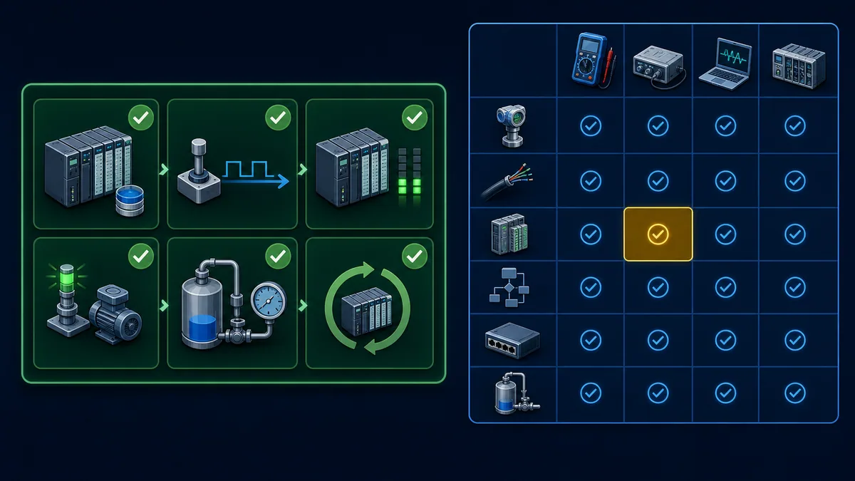
Use ten stages and stop at the first mismatch
- Confirm authorization, scope, hazards, isolation/test mode and rollback.
- Freeze the exact PLC, project, firmware, I/O/configuration and network baseline.
- Verify tester rating, mode, leads, calibration/self-check and known reference.
- Record initial process, electrical, PLC state and active alarms/forces.
- Observe the real signal without stimulation where safe and useful.
- Apply one controlled input at one defined boundary.
- Compare adjacent evidence: tester output, terminal, module raw, tag and state.
- Verify commanded output, physical output and process response independently.
- Run negative, boundary, timeout/loss and recovery cases authorized by plan.
- Remove tester/forces, restore configuration, compare checksums and prove normal state.
Define pass criteria before seeing the result
Write expected readings and tolerances before connecting the tester. Include normal and forbidden states, timing windows, alarm/event behavior, data quality/age, effects on unrelated channels and recovery. If the criterion is invented after observing the value, the test confirms expectation rather than requirement.
| Result field | Weak record | Release-quality record |
|---|---|---|
| Stimulus | “Input switched” | Tool/model/mode, connection, actual measured stimulus and time |
| Expected PLC state | “Bit should turn on” | Exact raw/tag/state and bounded response window |
| Actual PLC state | Screenshot only | Timestamped trace/export tied to project checksum |
| Output | “Motor ran” | Output image, terminal/load evidence and independent process response |
| Tolerance | “Looks close” | Calculated allowed range with uncertainty assumptions |
| Failure | “Did not work” | First failed boundary, raw evidence and ruled-out hypotheses |
| Restoration | “Removed leads” | Force/test flags cleared, wiring/config restored, checksum and normal proof |
| Review | Technician initials | Named executor/reviewer, deviations, approval and evidence location |
Troubleshoot tester results without moving the fault
Distinguish tester error from PLC or process error
When a result is surprising, verify the tester on a known reference and observe its actual output. Check wrong mode, discharged supply, blown meter fuse, lead placement, common/reference, loading, output compliance, calibration status, bandwidth and software sampling. A tester can create the symptom it is meant to diagnose.
Then compare the exact adjacent boundary. If current is correct at the terminal but raw counts are wrong, investigate module/configuration/reference. If raw counts are right and scale is wrong, inspect data type/scaling. If the output image changes but terminal does not, inspect output module/power. If the terminal changes but the process does not, move beyond the PLC toward load, actuator, interlocks and mechanics.
| Symptom during test | Highest-value checks | Likely boundary | Avoid |
|---|---|---|---|
| No digital input with tester ON | Tester actual output, common/reference, terminal voltage, module LED/raw | Harness/common/channel/config | Forcing application tag first |
| Input LED ON but tag OFF | Raw image, mapping, filter, task/data copy, tag writer | PLC configuration/program | Replacing sensor |
| Analog current correct, raw wrong | Channel mode/range, wiring, common/isolation, diagnostics | Analog input/module/config | Changing HMI scale first |
| Raw correct, engineering value wrong | Type, scaling, clamp, units, writer | PLC/HMI application | Recalibrating transmitter |
| Pulse present, count low | Electrical level, bandwidth, filter, edge, task/read/reset | High-speed input/config/program | Raising frequency further |
| Emulator passes, hardware fails | Unsupported feature, I/O electrical, task/firmware, network or field model gap | Simulation-to-real boundary | Calling the hardware faulty automatically |
| HIL passes, machine sequence fails | Model fidelity, interface difference, installation, untested state | Model/field/process | Expanding timing tolerance after failure |
| Test result changes with lead position | Connection resistance, reference/common-mode, interference, damaged lead | Test setup/physical path | Treating one reading as ground truth |
| Output image ON, no process action | Output power/module, starter/drive, interlocks, load/mechanics | Output-to-process chain | Assuming PLC logic is the only cause |
| Cannot restore normal state | Force/test flag, latched command, changed parameter/wiring | Test residue/change control | Leaving equipment in service |
Handle safety, security and change control explicitly
Treat every injected signal as a potential command
An input simulator can bypass a real limit, guard, pressure or level condition. An analog source can create a permissive or demand. A forced tag can skip normal logic. Even low-voltage work can lead to unexpected motion, heat, pressure, chemical release or stored-energy hazards. Test authorization must address the controlled process consequence, not just electrical voltage.
Use approved isolation/test modes, qualified people, defined observers, safe-state and abort criteria, interlocks and restoration. Apply OSHA 1910.147 and 1910.333 within their US scope; use applicable local law, standards and site procedures. Ordinary PLC simulation or forcing is not a substitute for a validated safety-system test or machine risk assessment.
Protect networked test tools and production controllers
Engineering laptops, emulators, APIs and HIL rigs can download projects, write tags or bridge networks. NIST SP 800-82 Rev. 3 emphasizes OT security compatible with safety, reliability and performance. Use approved test zones, least-required flows/credentials, protected project/model/result stores, verified software sources, logging and recovery. Do not connect an unmanaged “tester” to a production control network merely because it is convenient.
Version-control the test harness as carefully as the PLC application. Review changes to test code, process models and expected outcomes. A compromised or outdated oracle can approve defective logic at scale.
Diagnostic answer map for PLC tester questions
If someone asks what a PLC tester is
Explain that it is a role, not one device: a tool or system that applies a known stimulus and observes the next PLC boundary. Common classes are digital I/O signal boxes, loop/pulse/temperature simulators, meters/analyzers, software emulators and HIL rigs.
If someone asks how to test a PLC input
Identify the exact input type/common/threshold and isolate the field source under an approved plan. Apply known OFF/ON or calibrated analog points with a compatible rated tester. Compare tester output, terminal reading, module/raw input, application tag and downstream state, then restore and verify normal operation.
If someone asks which PLC tester to buy
Start from required boundaries and interfaces. Specify electrical compatibility, isolation/protection, accuracy/bandwidth, logging, automation/API, calibration/support and explicit limitations. A modular kit is usually more credible than an all-in-one claim.
If someone asks whether a PLC simulator can test real I/O
Software simulation can test supported logic, states and modeled interfaces; it does not prove real field wiring, thresholds, output power, actuator mechanics or environmental behavior. Add controlled hardware tests or HIL according to the remaining risk.
If someone asks how HIL differs from PLC simulation
HIL connects a real controller or runtime to a real-time plant model through deterministic interfaces. It adds closed-loop dynamics, coordinated I/O and repeatable faults, but depends on model and interface fidelity. Basic simulation may only manipulate tags or execute selected logic.
If someone asks where to practise PLC testing
Use the interactive PLC troubleshooting simulator to practise symptom classification, ordered checks and recovery evidence. It is not a calibrated source, exact vendor emulator, electrical tester or production acceptance system.
Frequently asked questions
What does a PLC tester do?
It generates or observes a known condition at a defined PLC boundary so actual behavior can be compared with an expected result. Depending on type, it may switch digital inputs, simulate 4–20 mA or pulses, execute PLC logic virtually, capture communications or run a real controller against a plant model.
Can I test a PLC with a multimeter?
A suitable meter can verify voltage, current, continuity/resistance or power at selected electrical points, but it cannot prove all PLC logic, timing, communications or process behavior. Use the exact meter mode/rating and circuit procedure; incorrect current-mode connection can create a short or blow the meter fuse.
How do I test a 24 VDC PLC input?
Confirm the exact module wiring, source/sink convention, common, thresholds and test authorization. Isolate the field source as required, apply a compatible current-limited/fused OFF/ON test signal, and compare terminal measurement, module indicator, raw input, application tag and downstream state. Restore and prove normal operation.
How do I test a 4–20 mA PLC analog input?
Determine whether the loop/channel is powered and whether the calibrator must source, simulate or measure. Inject approved points such as 4, 8, 12, 16 and 20 mA; record actual current, raw counts, scaled value, quality and alarms. Add approved fault/open-loop and recovery cases.
Can a PLC tester test outputs?
Some systems can observe or load outputs, but an input signal source must not be connected to an energized output. Output testing can energize hazardous loads. Use the exact module's approved method and a machine/process test plan controlling output power, interlocks, energy and physical response.
What is the difference between PLC simulation and emulation?
Simulation models selected behavior or a process; emulation reproduces a supported controller runtime closely enough to execute compatible projects. Vendors use terms differently, so rely on documented controller, firmware, instruction, timing, communications, motion and safety coverage rather than the label.
What is hardware-in-the-loop PLC testing?
HIL connects a real controller or controller runtime to a real-time plant model through deterministic I/O or network interfaces. It can run closed-loop scenarios and repeatable faults before the real machine is available. Results are only as credible as the model, interfaces, timing and test oracle.
Can online PLC testing replace a real PLC bench?
No universal online tester reproduces exact I/O electronics, field wiring, timing, firmware, communications, safety behavior and process dynamics. Online tools are valuable for logic learning and diagnostic practice. Use vendor emulation, representative hardware or HIL for requirements they genuinely cover.
What should be in a PLC test report?
Include requirement/test ID, exact PLC/project/firmware, tester/model/settings/calibration, connection point, initial state, stimulus, expected and actual readings/timing, result, traces/screenshots/captures, deviations, restoration/checksum proof, executor/reviewer and date.
Is forcing an input the same as using a PLC tester?
No. A force changes a software image or controller behavior and can test selected logic, but it does not prove field signal, wiring or input electronics. It can also create hazardous commands and persist unnoticed. Use forcing only under approved controls and verify all forces are removed.
Sources, review scope, and limitations
Primary sources used for this guide
- PLC Tools simulator/tester catalog and official support/manual index: manufacturer examples and manuals for analog, pulse, temperature and Ethernet tester categories.
- PLC Tools SIM-ALS loop simulator: manufacturer scope for a two-wire 4–20 mA transmitter simulator and its fixed test points.
- PLC Tools SIM-EOC pulse simulator: manufacturer scope for compatible open-collector pulse/encoder simulation and frequency cases.
- Fluke loop-power and 4–20 mA testing guide: manufacturer explanation of powering/measuring an offline transmitter.
- Fluke loop calibration and maintenance guide and mA loop calibrator catalog: source, simulate, measure and loop-power mode context.
- Siemens TIA Portal Test Suite V20 system-test introduction and basic test instructions: current official arrange/wait/assert, HIL/SIL and sampling limitations.
- Siemens S7-PLCSIM Advanced and SIMIT: official current emulation, co-simulation, HIL/SIL and product-family scope.
- Rockwell FactoryTalk Logix Echo and October 2025 Getting Results Guide: current supported controller, snapshot, API and emulation workflow boundaries.
- Speedgoat automated PLC testing and Speedgoat/MathWorks PLC HIL paper: primary vendor HIL, real-time plant model and PLC test-system context.
- NIST SP 800-82 Rev. 3: current final US OT-security guidance for safety, reliability, performance and cybersecurity controls.
- OSHA 1910.147 hazardous-energy control and OSHA 1910.333 electrical work practices: US isolation and electrical work-practice boundaries in their applicable scope.
Review and safety limitations
This guide is a tester-selection, test-design and evidence framework. It is not an electrical test instruction for a specific PLC, a calibrated procedure, safety validation, functional-safety proof test, machine/process risk assessment, HIL model validation, network authorization, vendor compatibility statement or energized-work procedure. Exact connections, thresholds, modes, tolerances, task timing, supported emulation behavior and safe states come from current product documentation and approved site engineering.
The nominal 24 VDC and 4–20 mA cases are educational templates. Replace all expected readings, tolerances, settling times and fault values with exact module/tool/process requirements and an uncertainty assessment. Never connect a generic source to an unknown or energized circuit, bridge safety devices, force production logic casually or infer output/process health from one indication.
The eight original generated visuals are explanatory abstractions. Their unbranded PLCs, meters, simulators, terminals, waveforms, safety fencing, HIL timing rings, software panels and green/amber markers are not exact products, certified wiring, calibrated readings, real packet/trace evidence or a validated protective system. Decorative interface text in the SIL visual is illustrative.
Use qualified automation, instrumentation, electrical, network, process and safety personnel; current manuals and approved drawings; suitably rated/calibrated tools; controlled test hardware or validated models; named authorization, observers and abort criteria; and site isolation, hazardous-area, cybersecurity, force/test-mode and restoration procedures. Revalidate after changes to PLC/module/firmware, project, wiring, tester/harness, calibration, network, emulator, process model, sampling/timing, test oracle, safety function or process requirement. Review this page when cited vendor documentation changes.
Now run it · free to start
Learn a repeatable way to find the fault
Split a stopped machine into input, logic, output and physical response, and take the measurement that proves each stage. Practised on simulated machines. Free to start.
Ownership disclosure: PLC Programming IO and PLC Simulation Software are operated by the same publisher.
PLC Programming IO Editorial Team
Industrial automation education, references, and software testing
The PLC Programming IO Editorial Team publishes sourced industrial-automation education and documents how material is reviewed, tested, and corrected. A team byline means the publisher is responsible for the page; it does not represent a fictional person or imply an engineering licence.
Coverage:
- • PLC programming concepts and examples
- • Vendor software tutorials and comparisons
- • SCADA, HMI, protocols, and instrumentation
- • Training, careers, and reference material
Review standard:
- • Prefer primary and official sources
- • Record software versions when material
- • Separate tested facts from estimates
- • Publish material corrections
Important scope note
This site provides education, not project-specific engineering approval. Safety, code, and compliance decisions require a qualified person with access to the actual machine and jurisdiction.