PLC Motor Control Starters: Logic, Feedback and Troubleshooting
Understand DOL and reversing motor starters, PLC command and proof logic, overload feedback, safe commissioning, and evidence-led troubleshooting.
Review status: Editorially reviewed against cited Siemens, Schneider Electric and Rockwell Automation motor-control documentation plus OSHA hazardous-energy requirements; component selection, short-circuit coordination, conductor sizing, terminal wiring, energy control and energized testing require the installed equipment documentation, engineered design and site authorization
Direct answer
A PLC motor-control starter uses a controller command to operate a contactor or solid-state starter while protective devices and feedback tell the control system whether the motor circuit is available, energized, tripped and producing the expected result. For a conventional direct-on-line starter, the functional chain is branch short-circuit protection, contactor, overload relay and motor. The control chain is request, permissives, PLC output, any interposing device, contactor coil, auxiliary feedback, overload status, motor-current proof and process proof.
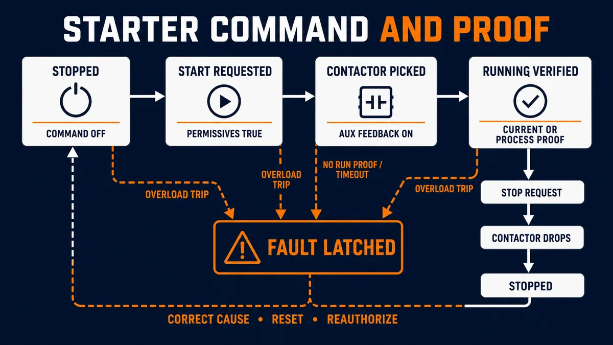
Good PLC logic does not equate an energized output bit with a running motor. It separates requested, commanded, picked up, electrically loaded and process proven states. It times the expected transition between them, latches meaningful first-out faults, prevents automatic restart until the cause and reset policy are satisfied, and records which boundary failed. A starter that has no auxiliary, overload or process feedback may be able to switch a motor, but it cannot support strong diagnostics.
This guide explains the functional design and diagnostic method. It is not a terminal-by-terminal wiring drawing, a component-sizing procedure or permission to work energized. The installed motor, starter, protective device, enclosure, supply and machine determine ratings, coordination, control voltage, stopping behavior and safe work boundaries.
Treat the starter as two connected paths
Follow the power path separately from control and feedback
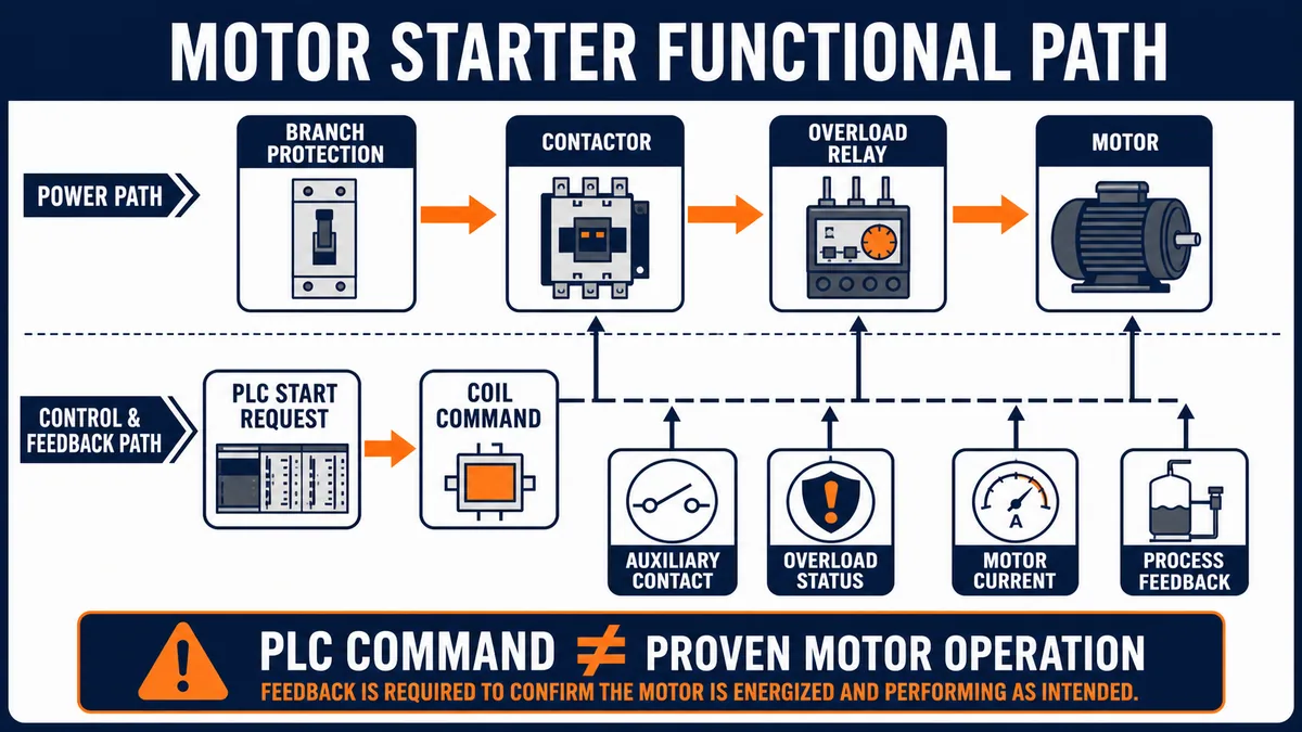
The power path carries motor current. In a common magnetic starter it passes through an upstream branch-protection device, the contactor's main poles and an overload relay before reaching the motor. The exact arrangement depends on the product family and applicable design. Siemens describes a starter as a combination that includes contactor switching and overload protection, while short-circuit protection and coordination must also be addressed for the assembly. A contactor is not automatically a branch short-circuit protective device.
The control and feedback path carries intent and evidence. The PLC evaluates mode, permissives, interlocks and safety-related status, then commands a suitable output/interface. The contactor coil changes the power path. An auxiliary contact can report mechanical contactor state; the overload relay reports a trip; current or process instruments can prove that the motor and driven equipment produced the expected result.
| Layer | Typical function | Evidence available to the PLC | What that evidence cannot prove alone |
|---|---|---|---|
| branch protection | interrupts specified short-circuit/fault conditions | device status if instrumented | correct coordination, intact downstream circuit or motor motion |
| contactor | repeatedly connects and disconnects motor power | auxiliary contact or smart-starter status | current in every phase or healthy motor/load |
| overload relay | detects sustained overload/phase-related conditions according to product design | healthy/tripped contact or network status | all short circuits or all mechanical faults |
| PLC output/interface | commands the starter coil/input | output logic and module diagnostics | coil voltage, contactor pickup or closed main poles |
| current/energy monitor | indicates electrical loading | current, power or threshold proof | correct direction, coupling or process delivery |
| process instrument | confirms pressure, flow, motion, level change or position | physical result and quality | which upstream electrical component failed |
Name each boundary in drawings, tags and alarms
Ambiguous names create ambiguous troubleshooting. Motor_Run might mean a request, an energized output, an auxiliary contact or a process-proven state. Prefer names that expose the boundary, such as M101_RunReq, M101_CoilCmd, M101_ContactorFb, M101_OverloadOk, M101_CurrentProof and M101_Running. The HMI can still show plain language, but the logic should not hide unlike meanings behind one bit.
| State or tag | Recommended meaning | Normal source | Useful mismatch |
|---|---|---|---|
| available | required control prerequisites are satisfied | permissive aggregation | unavailable while operator expects start |
| run request | supervisory/operator sequence wants operation | sequence or HMI mode logic | request persists after stop condition |
| coil command | PLC intends to energize the starter interface | final command rung/state | command true, contactor feedback false |
| contactor feedback | auxiliary evidence indicates pickup | physical auxiliary or starter status | feedback true, command false |
| running proved | chosen current/process evidence is valid | proof logic with quality/timing | contactor picked but result absent |
| overload tripped | protective device operated | overload auxiliary/network data | repeated reset without cause correction |
Apply a safe work boundary before diagnosis
A stop command is not energy isolation
OSHA's hazardous-energy rule explicitly states that push buttons, selector switches and other control-circuit devices are not energy-isolating devices. A PLC output that is off, an HMI showing “stopped,” an open auxiliary contact or a missing permissive does not establish an electrically or mechanically safe work condition. Stored, gravitational, pneumatic, hydraulic, thermal and process energy can remain even when the contactor is open.
Use the site-specific energy-control procedure and the installed equipment instructions. Qualified, authorized people must determine whether an action requires de-energization, verification, additional mechanical restraint or a controlled energized-test plan. Machine guarding and exclusion controls remain relevant whenever motion is possible.
| Proposed action | Boundary that must be established by the site | Why PLC/HMI status is insufficient |
|---|---|---|
| read event logs remotely | approved normal operating access | displayed values may be stale or mapped incorrectly |
| open a starter enclosure | electrical safe-work and hazardous-energy procedure | line and stored energy may remain |
| inspect the motor or load | control all relevant electrical and mechanical energy | stopped equipment can still move or release energy |
| test a coil or power circuit | qualified test plan and product-approved points | probing can expose hazardous voltage or alter state |
| reset and start | cause addressed, area clear and restart authorized | reset can permit immediate pickup and motion |
| change protection or timing | engineered review and controlled change | a symptom can be hidden while risk increases |
Keep ordinary control separate from safety functions
An ordinary PLC, contactor and software interlock should not be described as a safety function unless the entire architecture is specifically designed, selected, validated and maintained for that role. Emergency stopping, guard monitoring, prevention of unexpected startup and safe isolation require the machine's risk assessment and applicable safety design. This article's permissives and interlocks improve operational behavior and diagnostics; they do not claim a safety integrity level or performance level.
Choose the correct motor-control method
Use DOL when full-voltage fixed-speed starting fits the system
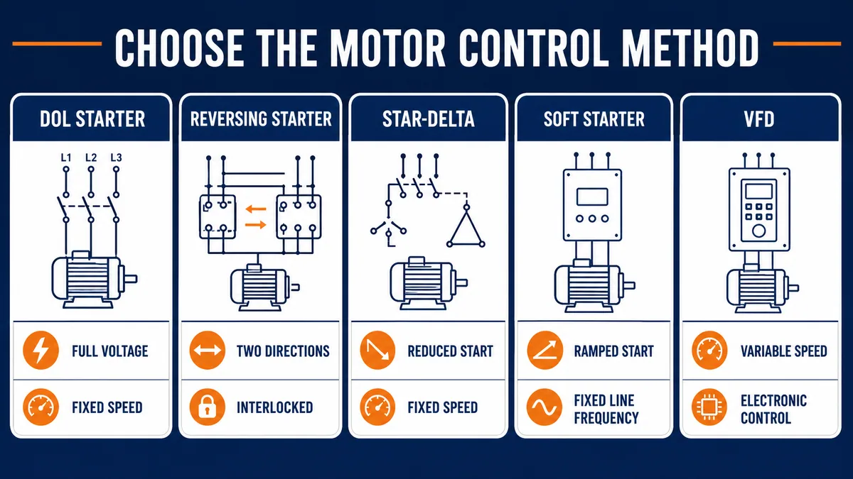
A direct-on-line (DOL), across-the-line or full-voltage starter applies the supply through a contactor to a fixed-speed motor. Schneider defines DOL as connecting the motor directly to the supply through the switching arrangement. It is conceptually simple, usually easy to diagnose and often appropriate when starting current, starting torque, mechanical shock and supply disturbance are acceptable for the motor and process.
A reversing starter adds a second contactor arrangement that swaps motor phase sequence for the opposite direction. PLC star-delta arrangements reduce starting current through a proved winding transition but introduce more devices, interlocks and transition logic. A soft starter ramps voltage for starting/stopping behavior while retaining line-frequency operation once bypassed or fully conducting. A VFD converts frequency and voltage to control speed and torque; see the dedicated VFD setup and wiring guide for that different architecture.
| Method | Best-fit control need | Main design consequence | Diagnostic focus |
|---|---|---|---|
| DOL starter | one direction, fixed speed, full-voltage start acceptable | simple hardware; high inrush and abrupt torque may matter | coil, pickup, overload, current and load proof |
| reversing starter | two directions at fixed speed | two contactors plus mechanical/electrical/logic interlocks | mutual exclusion, stop confirmation and direction proof |
| star-delta starter | reduced-current fixed-speed start for a suitable motor/system | multiple contactors and transition timing | state transition, contactor feedback and open/closed transition faults |
| soft starter | controlled voltage ramp without variable running speed | semiconductor starter, settings and often bypass behavior | start profile, current limit, bypass and trip history |
| VFD | variable speed/torque or controlled accel/decel | drive parameters, harmonics/EMC, motor compatibility and energy behavior | command/reference, DC bus, output, motor and process data |
Do not substitute one method without system review
Moving from DOL to a soft starter or VFD changes more than the PLC output. Protection, isolation, bypass, motor thermal behavior, output switching, cable/EMC practice, braking, stop category, fault response and process dynamics may change. Reversing a motor through contactors is also not equivalent to reversing a VFD command. The product manuals and engineered design own those rules.
Live mini-lab
Try it: press START, then STOP
A stop-dominant seal-in rung: START latches the motor output through its own contact, and STOP breaks the circuit.
Watch the output lamp: it stays on after START until you press STOP.
Free to start · runs in your browserOpens plcsimulationsoftware.com — same team
Build PLC command logic around explicit states
Separate request, permission, command and proof
The PLC should derive the coil command only after mode ownership and permissives are resolved. Typical operational permissives might include an available upstream process, no active overload, required valves or dampers in suitable states, and a sequence-ready condition. A safety system's status may be an input to ordinary logic, but the standard PLC should not bypass or recreate the safety function.
After command, start a pickup/proof expectation. If auxiliary feedback does not appear within the engineered time, stop the command as the machine design requires and latch a “commanded but not picked” diagnostic. If pickup occurs but current or process proof does not, report the next boundary. During a normal stop, expect feedback to drop; “feedback stuck on after command off” is a different fault from “failed to pick.”
| Transition | Entry evidence | Expected evidence | Example diagnostic if expectation fails |
|---|---|---|---|
| stopped to requested | owner requests run, permissives true | request state accepted | unavailable/permissive first-out |
| requested to commanded | sequence authorizes output | output command and healthy module/interface | command path unavailable |
| commanded to picked | coil command active | contactor auxiliary changes in allowed time | contactor failed to pick |
| picked to running | contactor feedback active | current or process proof appears | starter on but motor/process not proven |
| running to stopped | stop request or sequence completion | command off, feedback/proof clear appropriately | contactor feedback failed to drop |
| any active state to fault | overload, mismatch, timeout or protected stop | command response defined by machine design | first-out fault and restart inhibit |
Treat seal-in behavior as a state, not a mystery contact
Traditional three-wire control uses momentary start/stop devices and a maintaining auxiliary “seal-in” path. Two-wire control uses a maintained run request. A PLC can model either intent, but the restart consequence differs. A maintained request can still be present when power or a permissive returns. The program therefore needs an explicit restart policy: automatic restart where engineered and permitted, a new rising edge, operator acknowledgement, or a full reset-and-reauthorize sequence.
Do not create two independent latches—one hidden in hardwired control and another in the PLC—without defining ownership. Otherwise the HMI may show command off while the contactor remains sealed, or the PLC may reassert a stale request after a hardwired stop recovers. Document whether hand/local mode bypasses PLC command, which stops remain effective in every mode, and how status returns to the controller.
| Control pattern | Request persistence | Principal risk | Strong PLC treatment |
|---|---|---|---|
| momentary start/stop | PLC state retains run intent | hidden reset or lost-state behavior | explicit state machine and reset policy |
| maintained two-wire request | external signal remains true | unexpected restart after recovery | reauthorization/edge logic where design requires |
| hardwired seal-in | contactor circuit retains itself | PLC does not own actual state | read real auxiliary/overload status and document ownership |
| hand-off-auto selector | different sources own command | source conflict or misleading HMI | exclusive owner state and source-specific indication |
| networked smart starter | command/status words retain protocol state | stale data or recovery behavior | quality, heartbeat, timeout and recovery policy |
Use overload protection and feedback correctly
Distinguish overload, short-circuit and process protection
An overload relay protects against specified sustained motor overcurrent/thermal conditions according to its design and setting. It is not a universal short-circuit device and does not prove that every phase, cable, bearing or driven process is healthy. The Siemens SIRIUS documentation treats overload relays, contactors and motor-starter protectors as distinct devices with product-specific coordination and application data. Settings must follow the motor nameplate, service/duty, installation, design study and exact manual—not a generic percentage copied from another panel.
PLC logic should normally read the overload status independently from the auxiliary contact. If both are collapsed into one “motor not running” bit, the operator cannot tell whether the contactor failed to pick, overload tripped, control power disappeared or the process stopped the request. Smart starters may expose trip class, phase imbalance, current and maintenance data, but the mapping and quality must be verified.
| Evidence pattern | Likely boundary | Next safe evidence question |
|---|---|---|
| overload healthy, command true, auxiliary false | coil/interface/contactor path | did the command reach the approved interface and did pickup occur? |
| overload tripped after long run | sustained load, phase or thermal class | what current, duty, ambient and mechanical condition preceded trip? |
| overload trips during every start | start profile, setting, motor/load or phase issue | does exact product history align with acceleration current and time? |
| auxiliary true, current proof absent | main circuit, motor cable/motor or sensing | is main-power delivery present under an authorized diagnostic plan? |
| current normal, process proof absent | coupling, driven equipment or instrument | is the motor turning the intended load and is feedback trustworthy? |
| device status changes without aligned PLC event | mapping, signal quality or control supply | are raw input, network quality and timestamps valid? |
Reset only after the cause and restart conditions are addressed
An overload reset changes device state; it does not correct a jam, single-phasing, blocked cooling, wrong setting or excessive starts. Preserve trip data before reset. Confirm the exact reset mechanism and whether it is manual, automatic or remote-capable for the installed device. Remote or automatic reset can create a restart path and must match the risk assessment, machine behavior and site rules.
Interlock forward and reverse starters at every appropriate layer
Prevent simultaneous contactor pickup independently of PLC logic
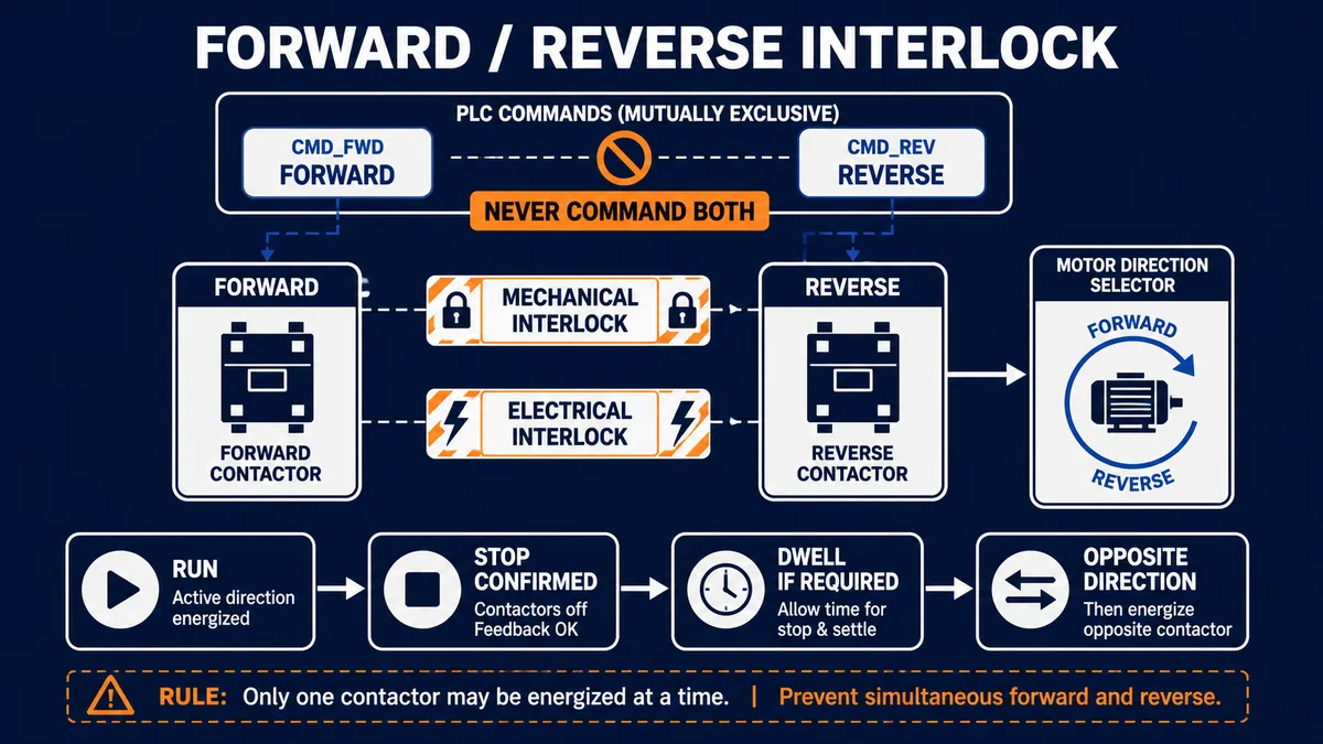
A reversing starter must prevent forward and reverse contactors from closing together. Use the product's approved mechanical interlock, appropriate electrical interlocking and mutually exclusive PLC commands as required by the engineered design. PLC mutual-exclusion logic is useful, but it is not a substitute for physical/electrical measures because an output fault, wiring error, forced point or program defect can exist outside the intended logic.
Direction change also needs a controlled sequence. Remove the active command, verify both contactors are off, allow the required motor/load stop or dwell, confirm conditions for reversal, then energize the opposite direction. The required zero-speed proof, dwell and braking behavior are application-specific. A plug-reversal or rapid direction change can create high electrical and mechanical stress and must not be improvised.
| Reversing check | Expected condition | Fault response concept |
|---|---|---|
| command exclusivity | never forward and reverse requests simultaneously | block both, latch conflict and require investigation |
| mechanical interlock | one contactor physically prevents the other | inspect/verify through approved maintenance procedure |
| electrical interlock | opposite auxiliary state interrupts each coil path | treat missing/stuck state as control-circuit fault |
| feedback exclusivity | never both contactor feedbacks true | remove commands according to design and escalate |
| stop confirmation | active feedback and motion proof clear | do not issue opposite command |
| dwell/zero-speed condition | application-specific transition satisfied | hold transition and identify unmet condition |
Commission the starter as an evidence matrix
Test normal transitions before injecting faults
Commissioning should verify documented behavior from input to physical result, not merely show that the motor turns once. Begin with identity and controlled records: motor/starter/protection data, supply and control voltage class, PLC and I/O revision, drawings, modes, interlocks, overload settings, approved direction and safe test boundary. Confirm signal quality and inactive states before authorizing motion.
Then execute an approved sequence for unavailable, start, running and stop states. Observe raw I/O, processed tags, command, auxiliary, overload, current/process proof, HMI state, timestamps and alarms together. Verify that a normal stop is not logged as a fault and that a failed expectation identifies the correct boundary. Fault injection should be performed only where the test plan, risk assessment and equipment method allow it; never create a hazardous electrical or mechanical fault to test an alarm.
| Commissioning case | Stimulus or precondition | Expected PLC/HMI evidence | Acceptance focus |
|---|---|---|---|
| unavailable start | one approved operational permissive false | request rejected with specific first-out | no coil command; message names real condition |
| normal start | all conditions true, authorized start | command, pickup, current/process proof in order | transition times and timestamps credible |
| normal stop | approved stop request | command off then feedback/proof clear | no nuisance trip; stop state unambiguous |
| pickup failure simulation | approved non-hazardous signal/test method | timeout identifies command-to-aux boundary | command response and latch meet design |
| process proof loss simulation | approved instrument/test method | motor electrical state distinguished from process result | no false claim that PLC output failed |
| overload status test | manufacturer/site-approved test facility | overload-specific fault and restart inhibit | raw status, alarm, reset and authorization correct |
| mode transfer | controlled hand/auto ownership change | one owner, explicit source indication | no bump or unexpected restart |
| PLC/network recovery | controlled recovery test | documented retained/cleared request behavior | no stale command causes unintended motion |
Record timing from the real machine
Pickup, current-proof, process-response and rundown times vary. Configure expectations from approved equipment data and observed healthy behavior with margin, not arbitrary one-second timers reused everywhere. A pump may build pressure slowly; a conveyor sensor may not change until material arrives; an unloaded motor-current threshold may be close to noise. Record median and worst credible healthy transitions, sensor quality and operating modes. Revalidate after meaningful mechanical, motor, starter, PLC or process changes.
Troubleshoot by climbing the evidence ladder
Compare request, command, pickup, current and process result
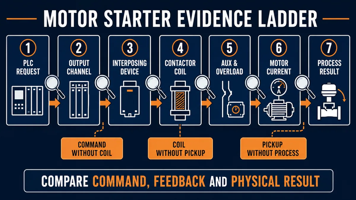
Start at the earliest boundary where expected and observed state diverge. If there is no PLC request, investigate mode/sequence ownership rather than the contactor. If request exists but output command does not, inspect permissives, program state and module diagnostics. If output is commanded but auxiliary does not change, inspect the authorized coil/interface path. If auxiliary changes but no current or process proof follows, move to the main power, motor and load boundary under the proper safety plan.
| Symptom | First discriminating comparison | Do not assume |
|---|---|---|
| HMI says motor should run, no PLC request | HMI/sequence owner versus processed request | contactor is faulty |
| request true, coil command false | permissives, trips, mode and final command logic | output module is faulty |
| coil command true, auxiliary false | module/interface diagnostics and real contactor state | main motor circuit is healthy or failed |
| auxiliary true, motor current absent | approved power-path evidence and current-sensor validity | auxiliary proves main poles/current |
| motor current present, process unchanged | shaft/coupling/load/instrument evidence | motor electrical circuit is the cause |
| starter drops intermittently | aligned command, control power, overload and auxiliary timeline | every dropout is a PLC scan problem |
| overload repeats | current/duty/phase/load/cooling history | reset is a repair |
| wrong direction | approved direction record, phase/control history and mechanical result | changing code alone is safe |
Preserve first-out and sequence context
Contactors often drop when any upstream condition removes the command. If the HMI logs “contactor off” after the overload or process trip, the dropout is an effect. Preserve first-out timestamps, raw signal changes, command owner, sequence step and device status. Clocks across PLC, HMI and smart starter may differ, so record offsets or synchronize through the approved architecture.
If a conventional starter problem is actually part of a drive application, use the VFD fault troubleshooting guide because drive fault codes, DC-bus behavior, command/reference sources and output rules change the diagnostic tree.
Diagnostic answer map for PLC motor starters
| Question a technician or AI assistant may ask | Short, extractable answer | Evidence that decides it |
|---|---|---|
| Why is the PLC motor output on but the motor is not running? | The output proves only controller intent; check interface/coil, auxiliary pickup, overload, main-power/current and process proof in that order. | raw output diagnostics, contactor feedback, overload status, current and physical result |
| What does a contactor auxiliary contact prove? | It normally indicates contactor mechanism state; it does not alone prove balanced motor current, rotation or process output. | exact auxiliary arrangement plus current/process feedback |
| Why does a motor starter trip after several minutes? | Sustained load, phase condition, duty, cooling, motor data or protection setting are candidates; preserve current and trip history before reset. | overload record, phase/current trend, duty, load and installed manual |
| Should a PLC automatically reset an overload? | Only if the engineered risk assessment, equipment instructions and restart policy explicitly permit it; reset can enable unexpected motion. | device capability, machine risk assessment and authorization logic |
| How should a reversing starter be interlocked? | Use approved mechanical and electrical interlocking plus mutually exclusive commands, then verify stop/dwell before reversal. | product assembly design, feedback exclusivity and transition record |
| Is a PLC stop bit safe isolation? | No. Control devices and software states are not energy-isolating devices. | site hazardous-energy procedure and verified isolation state |
| When is a VFD better than a starter? | Choose a VFD when variable speed/torque or controlled dynamic behavior justifies the extra drive-system requirements. | load profile, process needs, supply, motor and stopping/energy study |
| What is the best motor-starter alarm? | A boundary-specific first-out alarm such as “commanded, contactor not picked” is more actionable than “motor failed.” | request, command, timed auxiliary and proof states |
Frequently asked questions
What is a PLC motor starter?
A PLC motor starter is a motor switching and protection arrangement whose command and status are integrated with a programmable controller. A conventional magnetic starter commonly combines a contactor and overload relay, with separate branch short-circuit protection/coordination addressed by the design. The PLC decides operational intent and uses feedback to describe pickup, trip and real running state.
What is the difference between a contactor and a motor starter?
A contactor is an electrically operated switching device. A motor starter includes switching plus motor-overload protection as an assembly or coordinated combination; the complete motor branch also requires the appropriate disconnecting, short-circuit, conductor, enclosure and coordination design. Product terminology and construction vary, so use the exact manufacturer's documentation.
Can a PLC output drive a contactor coil directly?
Only when the output type and rating, coil characteristics, inrush, suppression, control voltage, fault behavior and applicable design all permit it. Many systems use an interposing relay or dedicated starter interface. Do not decide from nominal voltage alone; verify the exact PLC module and contactor documentation and the engineered drawings.
Why use an auxiliary contact as PLC feedback?
An auxiliary contact gives independent evidence that the contactor mechanism changed state. It lets the PLC detect commanded-but-not-picked and feedback-stuck mismatches. It still does not prove current through every main pole, motor rotation or successful process output, so higher-value applications add current or process proof.
How should PLC seal-in logic work for a motor starter?
Represent the run intent as an explicit state with defined set, stop, fault and recovery conditions. Document whether the physical control is momentary, maintained or hardwired-sealed and which layer owns the command. Define whether a returning permissive requires a new start edge, acknowledgement or automatic recovery; avoid hidden latches in multiple layers.
What causes a motor starter overload to trip?
Possible causes include sustained mechanical overload, jam, excessive starts, phase/current imbalance, supply or connection problems, unsuitable motor/starter application, cooling or ambient conditions, and incorrect product selection or settings. Exact trip behavior is device-specific. Preserve current, timing and device history before resetting or changing anything.
How do you troubleshoot a motor starter that will not pull in?
First confirm a legitimate run request, permissives and the actual PLC output/interface diagnostic. Then, under the site's authorized work method, compare the coil-command boundary with contactor auxiliary state, overload/control status and control-power path. Do not jump straight to the main motor circuit, and do not probe energized equipment without authorization.
Why does a contactor chatter or drop out intermittently?
Candidates include unstable control voltage, loose or failing control-path components, a marginal coil, mechanical wear/contamination, a bouncing permissive, overload action or a changing PLC command. Align high-resolution command, input, control-power and auxiliary evidence. Repeated chatter can damage equipment, so isolate and escalate according to the site procedure.
How do you reverse a motor with two contactors?
A purpose-designed reversing starter changes the phase sequence through approved forward and reverse contactor arrangements. It must prevent simultaneous closure with appropriate mechanical and electrical interlocks as well as PLC command exclusion. Direction change must follow the machine's verified stop, dwell/zero-speed and restart conditions; this guide is not a field-wiring diagram.
Is a soft starter the same as a VFD?
No. A soft starter controls applied voltage during starting and sometimes stopping, while the motor normally runs at line frequency. A VFD converts the supply to control output frequency and voltage for variable-speed/torque operation. Their protection, bypass, motor, output-switching, EMC, control and diagnostic requirements differ.
Sources, review scope, and limitations
This article synthesizes functional and diagnostic principles from the following primary sources. The conceptual graphics deliberately omit terminals, conductor sizes, ratings and prescriptive wiring. Always use the exact installed product manuals, engineered drawings, applicable codes/standards, machine risk assessment and site procedures.
- Siemens Industrial Controls Catalog (2026) — current portfolio and application context for contactors, overload relays and motor-control equipment.
- Siemens SIRIUS Classic System Manual — starter combinations, contactor/overload functions and coordination context.
- Siemens SIRIUS 3RV Motor Starter Protectors Manual — product-specific protection, application and coordination information.
- Siemens SIRIUS 3RM1 Motor Starter Manual — compact starter function, status and application constraints.
- Siemens SIRIUS 3RT Contactors Equipment Manual — contactor selection, use and product-specific requirements.
- Siemens SIRIUS 3RU/3RB Overload Relays Manual — overload-relay functions, settings and diagnostics.
- Siemens SIRIUS Contactors Catalog Section (2025) — current contactor application and coordination tables for exact products.
- Schneider Electric: Direct-On-Line Starter definition — definition and functional description of DOL starting.
- Schneider Electric: Motor Control — motor-control terminology and application context.
- Schneider Electric: TM3 Motor Starter Module — PLC expansion/starter interface characteristics and constraints.
- Rockwell Automation NEMA Full-Voltage Starters — full-voltage starter types and product context.
- OSHA 29 CFR 1910.147, Control of Hazardous Energy — energy-isolation definitions and hazardous-energy control requirements.
- OSHA interpretation: motor starter circuits and lockout/tagout — application of hazardous-energy rules to motor control.
- OSHA Machine Guarding: General Requirements — guarding principles where machine motion can expose people to hazards.
Now run it · free to start
Learn a repeatable way to find the fault
Split a stopped machine into input, logic, output and physical response, and take the measurement that proves each stage. Practised on simulated machines. Free to start.
Ownership disclosure: PLC Programming IO and PLC Simulation Software are operated by the same publisher.
PLC Programming IO Editorial Team
Industrial automation education, references, and software testing
The PLC Programming IO Editorial Team publishes sourced industrial-automation education and documents how material is reviewed, tested, and corrected. A team byline means the publisher is responsible for the page; it does not represent a fictional person or imply an engineering licence.
Coverage:
- • PLC programming concepts and examples
- • Vendor software tutorials and comparisons
- • SCADA, HMI, protocols, and instrumentation
- • Training, careers, and reference material
Review standard:
- • Prefer primary and official sources
- • Record software versions when material
- • Separate tested facts from estimates
- • Publish material corrections
Important scope note
This site provides education, not project-specific engineering approval. Safety, code, and compliance decisions require a qualified person with access to the actual machine and jurisdiction.