VFD Fault Troubleshooting: Codes, Causes and Evidence-Led Tests
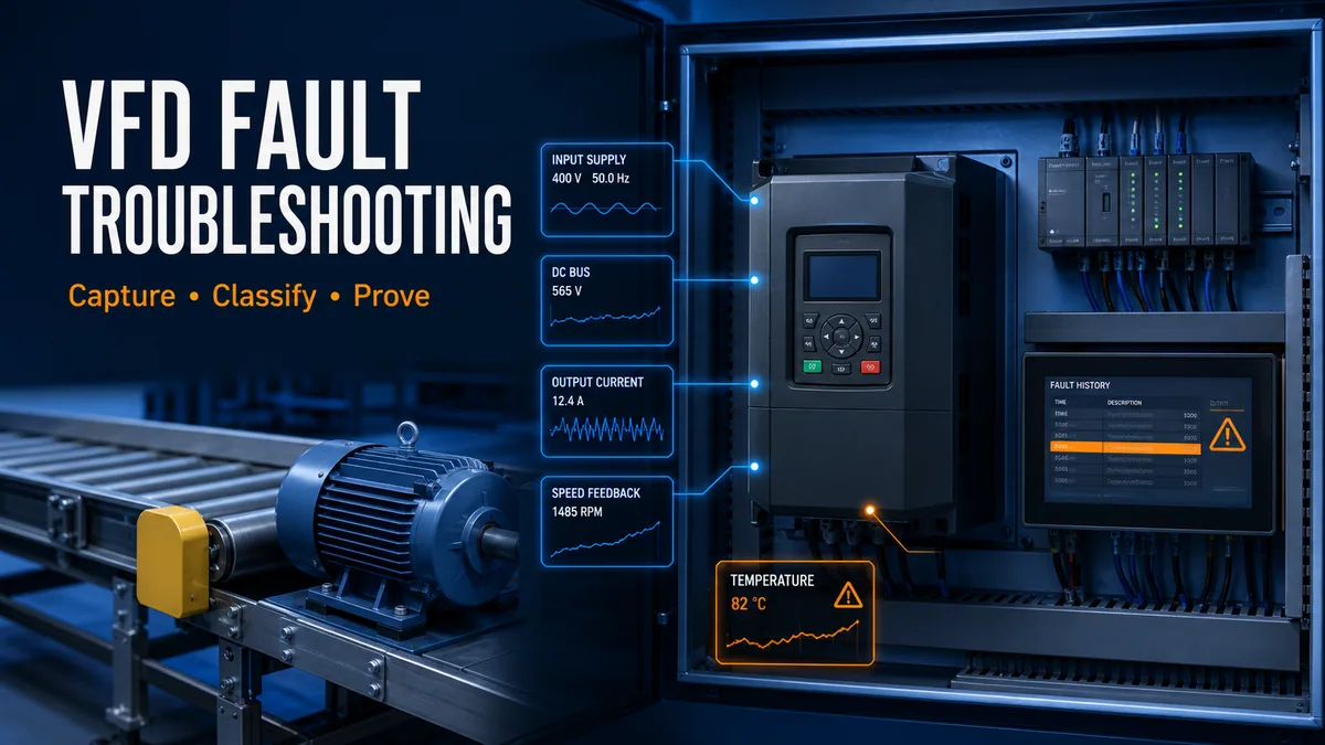
Troubleshoot VFD faults by preserving first-out evidence, classifying input, DC-bus, output, motor, load, thermal and control causes, then proving one boundary safely.
Review status: Editorially reviewed against cited Rockwell Automation, Siemens, ABB and Schneider Electric drive documentation plus OSHA hazardous-energy requirements; exact fault meaning, permitted measurements, energy-control steps, parameters, limits and restart decisions require the installed drive manual and site authorization
Direct answer
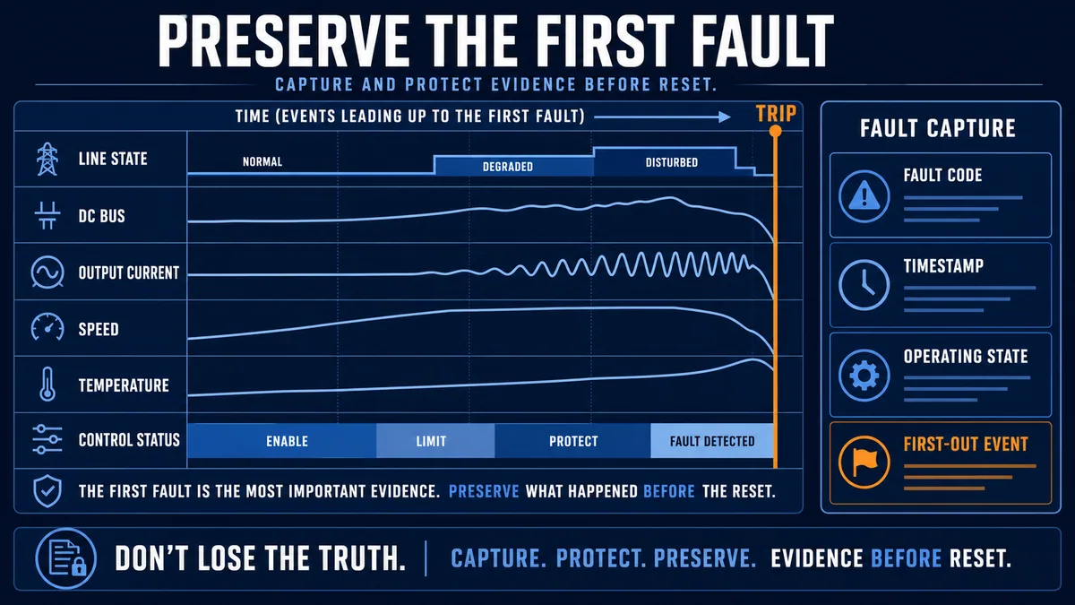
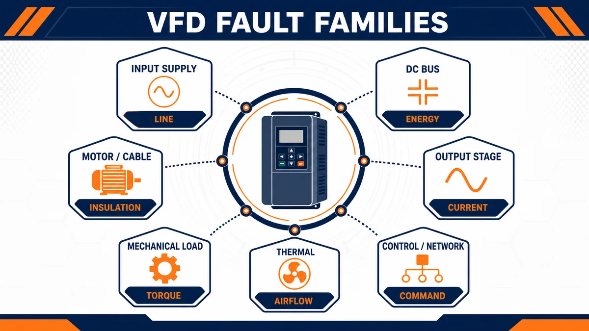
To troubleshoot a VFD fault, preserve the exact first fault code, timestamp, operating state and drive history before reset. Identify whether the event occurred at power-up, enable, acceleration, steady running, deceleration or stop. Then classify the evidence into an input-supply, DC-bus, output-stage, motor/cable, mechanical-load, thermal, control/reference, communications or internal-drive fault family. Apply the energy state required by the site procedure before inspection or testing, prove one boundary at a time, correct the demonstrated cause, reset once and verify under an approved operating test.
Do not repeatedly reset a drive to “see if it clears.” A reset acknowledges a detected condition; it does not repair loose power, a shorted motor cable, obstructed cooling, an overhauling load, a stale speed reference or a configuration defect. Repeated starts can worsen damage or create unexpected motion. Preserve fault history and first-out evidence, and stop/escalate when a serious fault repeats, the safe test boundary is unclear, or manufacturer instructions require service.
The fault name is only the start. Rockwell documentation, for example, associates undervoltage with a DC bus below a minimum, overvoltage with high line/transients or motor regeneration, overcurrent with excess current, and ground fault with an earth-current path. Other drive families use different codes, thresholds, reactions and diagnostic values. Decode the exact code using the exact product, firmware and option-module manual—never a generic internet list.
Start with electrical and mechanical safety
Treat the drive as an energy-conversion system
A VFD contains hazardous line-side, DC-link and output-side energy. Stored DC-bus energy can remain after input power is removed. The motor and load can store or generate mechanical energy. A run command removed in software, a stopped motor, an open permissive or an STO indication is not by itself verification of an electrically de-energized work condition.
Follow the site-specific hazardous-energy and electrical safe-work procedure and the drive’s discharge/wait/verification instructions. Qualified, authorized personnel must select the test equipment, exposure controls and measurement points. OSHA’s lockout/tagout guidance requires control of hazardous energy and defines a specific sequence when energy must temporarily be restored for testing or positioning; this article is not that procedure.
| Planned action | Required boundary before action | Why a screen indication is insufficient |
|---|---|---|
| read HMI/PLC/drive history remotely | approved normal operating access | remote data may be stale or mapped incorrectly |
| open an enclosure | site electrical/hazardous-energy procedure | hazardous voltage and stored energy may remain |
| inspect motor or driven equipment | all relevant electrical, mechanical and process energy controlled | motor stop does not restrain gravity, pressure or stored motion |
| disconnect or insulation-test motor cable | drive/motor instructions plus verified isolation | test voltage or reconnection can damage electronics or expose personnel |
| energize for diagnostic measurement | authorized energized-test plan and qualified personnel | ordinary maintenance isolation no longer protects the test boundary |
| reset and run | cause corrected, area cleared and restart authorized | reset can permit immediate torque or sequence restart |
Know when to stop and escalate
Escalate rather than continue when the code indicates an internal power-stage or safety fault, visible/odor/thermal damage exists, protective devices operated, a ground/short condition is suspected, the correct manual is unavailable, the drive identity/parameters do not match the controlled record, or the same serious fault repeats after one evidenced correction. Do not bypass an interlock, increase a limit or disable protection merely to keep production running.
Preserve the first fault before resetting
Capture code, port, source and history
Modern drives may distinguish faults, alarms, inhibits, events and safety faults. Rockwell manuals show product-dependent categories and sometimes include a port or source in the displayed code. Siemens list manuals document fault/alarm numbers, message values, reactions and acknowledgement. ABB firmware documentation separates fault tracing from parameter and fieldbus sections. Capture the complete displayed information rather than only the short description.
Record drive/catalog and firmware, option modules, exact code/text, secondary code or message value, source/port, time, fault queue order, status/control words, active command source, speed/torque reference, actual output frequency/speed/current, DC bus, temperature, digital I/O, network state, PLC sequence state and what the machine was physically doing. Photograph or export the history if permitted.
| Evidence field | Example meaning | Diagnostic value |
|---|---|---|
| first fault versus later faults | earliest causal detection versus cascade effects | prevents chasing secondary network or stop events |
| trip phase | power-up, enable, accel, steady, decel or idle | narrows relevant energy and control mechanisms |
| command source | keypad, terminals, PLC network or application block | identifies which control path owned the request |
| requested/actual speed | demand versus physical/estimated response | separates reference, current limit, motor and load issues |
| current/torque | load demand at event | reveals acceleration, jam, overload or short-current pattern |
| DC bus/line status | energy supply/return behavior | supports under/overvoltage classification |
| temperature/runtime | thermal state and operating duration | separates instant electrical trips from accumulated heating |
| sequence/interlocks | machine state and first-out condition | distinguishes drive trip from an upstream stop request |
Synchronize drive, PLC and process timelines
The drive clock, PLC clock, HMI event server and historian may not agree. Record their offsets or synchronize them through the approved architecture. A two-second ordering error can reverse the apparent sequence between “PLC removed run,” “drive faulted” and “contactor feedback dropped.” Retain raw timestamps and quality rather than rewriting the narrative after the fact.
Separate a drive fault from a no-run condition
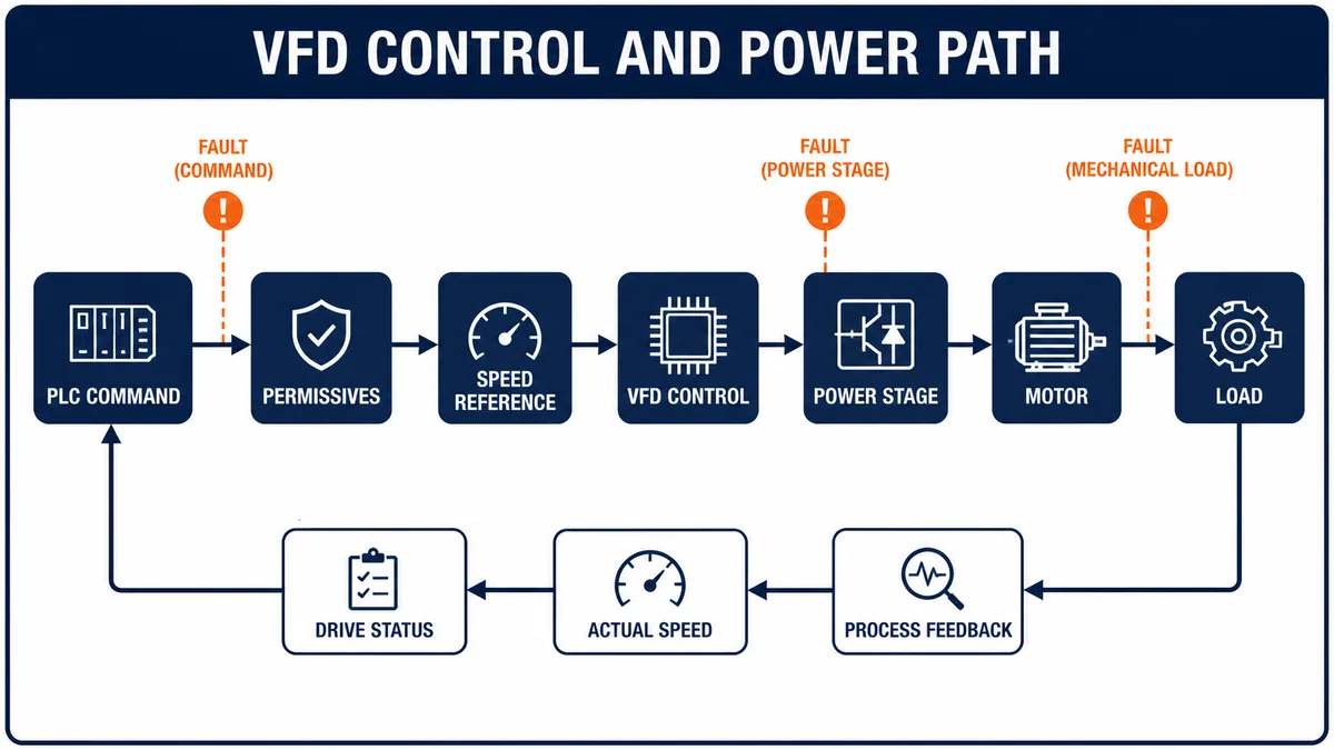
Follow command, permission, power and feedback paths
A motor can fail to run while the VFD is healthy. The PLC may not be commanding run, the selected command/reference source may be local, an enable/permissive may be missing, a safety function may be active, the reference may be zero, the drive may be current-limited, or the mechanical load may be blocked. Conversely, a drive can display ready while a downstream contactor, motor cable or coupling prevents physical result.
| Observation | First comparison | Likely boundary |
|---|---|---|
| PLC says run, drive says stopped | PLC output/request versus drive control word and selected source | network/I/O mapping, local/remote mode or permissive |
| drive ready, no speed reference | requested versus selected/effective reference | source selection, scaling, preset/reference override |
| drive running, output frequency present, motor stationary | drive output/status versus motor and mechanical feedback | output circuit, motor, brake, coupling or load |
| motor turns, process does not change | shaft/load/process feedback | coupling, valve/damper, belt, pump/process condition |
| drive faulted after upstream stop | timestamped first-out sequence | drive may be secondary to power or control removal |
| repeated reset request but fault remains | active condition and reset edge/acknowledgement | cause still present, wrong reset interface or non-resettable service condition |
Schneider documents application cases where actual speed and reference disagree because preset-speed or limit-switch functions interfere, or PDO units/mapping are inconsistent. That is why “the PLC tag is right” is not the endpoint; inspect the effective drive source and status.
Classify the fault family before testing
Use the code to choose a system boundary
The code describes what a drive detected, not necessarily where the physical cause lives. Overcurrent can arise from a short, motor fault, abrupt acceleration, excessive boost, wrong motor data or a jam. Overvoltage can arise from incoming supply conditions or regenerated mechanical energy. Overtemperature can result from ambient, blocked airflow, failed fan, switching settings or excessive load. Classify broadly, then use timing and supporting values to discriminate.
| Fault family | Supporting evidence | Competing explanation to exclude |
|---|---|---|
| input supply/power loss/phase loss | line monitor, protective-device state, DC-bus trend and other loads | a normal commanded power removal after another fault |
| DC-bus undervoltage | low bus at trip, line sag/interruption, precharge state | drive logic/control supply reset or upstream contactor action |
| DC-bus overvoltage | bus rise during decel/overhauling, high incoming line/transient | wrong fault decode or a downstream stop event |
| output overcurrent/short/ground | instantaneous current, trip phase, approved motor/cable tests | aggressive accel/boost, wrong motor data or jam |
| motor overload | thermal model, sustained current/torque, speed and duty | output short or drive thermal limit |
| drive overtemperature | heatsink/internal temperature, fan/airflow, ambient and load | motor temperature or cabinet sensor fault |
| control/reference/network loss | control words, source selection, timeout, analog quality | real power/motor fault that caused communications to drop |
| internal/hardware | self-test, precharge, memory, power-stage or safety diagnostics | external conditions specifically listed by the manual |
Live mini-lab
Try it: press START, then STOP
A stop-dominant seal-in rung: START latches the motor output through its own contact, and STOP breaks the circuit.
Watch the output lamp: it stays on after START until you press STOP.
Free to start · runs in your browserOpens plcsimulationsoftware.com — same team
Diagnose input supply and DC-bus faults
Undervoltage and power-loss faults
Rockwell’s PowerFlex 40P manual associates power-loss/undervoltage conditions with low DC-bus voltage and advises checking incoming AC and fuses for that product. A low-bus event can be caused by a utility or plant sag, opening protective device/contactor, weak connection, undersized source, phase loss, transformer interaction, rapid cycling or a drive/precharge defect. The diagnostic discriminator is the aligned line/bus/contactor history—not replacement by guess.
If several drives fault together, compare their timestamps and shared source. If one faults only under acceleration, compare input and bus trends with load/current and source capacity. If it faults at power-up, inspect precharge and input sequence through manufacturer-approved diagnostics. Do not defeat precharge or repeatedly cycle power.
Overvoltage faults during deceleration
When a motor/load regenerates, energy returns to the DC bus. Rockwell documentation explicitly lists motor regeneration as one cause of bus overvoltage and suggests product-specific responses such as longer deceleration or an approved dynamic-brake option. An overhauling conveyor, centrifuge, hoist or high-inertia load can continue driving the motor while the VFD tries to slow it.
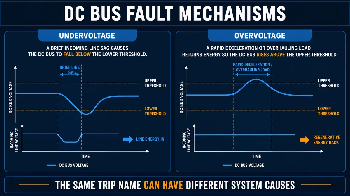
Do not lengthen deceleration blindly. The process may have a required stopping performance, and a brake resistor or regenerative unit requires correct product compatibility, sizing, protection, installation and thermal design. Escalate changes through machine/process and safety impact review.
| When bus fault occurs | Evidence to compare | High-value inference |
|---|---|---|
| immediately at line power | input presence, precharge state and prior shutdown | supply sequence, precharge or internal fault family |
| when other large load starts | line event across multiple devices | shared supply sag/disturbance |
| only at hard acceleration | current demand, line and bus trend | source impedance/capacity or overload interaction |
| only at rapid deceleration | falling speed with rising bus | regenerative-energy management |
| while overhauling load drives motor | torque direction, speed and bus rise | load is returning energy |
| randomly at steady state | line/event recorder, connections and environment | transient, intermittent power path or sensing issue |
Diagnose overcurrent, ground and motor faults
Use trip timing to distinguish current mechanisms
An instantaneous trip at enable suggests a different class from a thermal overload after twenty minutes. Rockwell’s PowerFlex 527 manual associates inverter overcurrent with current beyond the instantaneous hardware limit and lists motor power-cable shorts, winding shorts, conductor issues, rating and acceleration profile among checks for that product. Its ground-current description points toward excessive earth current. Follow the exact drive manual; do not assume one vendor’s label/action maps to another.
| Trip timing | Evidence to preserve | Candidate classes |
|---|---|---|
| at enable before rotation | current spike, output switching state and motor/cable condition | short/ground path, output contactor sequence, wrong connection or power stage |
| early acceleration | current/torque limit, accel command, brake release and load movement | jam, brake held, aggressive ramp, wrong motor data or undersized drive |
| near target speed | load curve, field-weakening region and supply | process demand, tuning/identification or voltage limitation |
| after sustained operation | thermal model, RMS current, motor temperature and duty | overload, cooling, low-speed thermal behavior or rating |
| during direction change | speed, zero crossing, command sequence and load inertia | reversal without suitable decel, mechanical shock or logic race |
| after output switching | contactor/bypass status and manufacturer rules | prohibited switching or transient at drive output |
Isolate motor, cable and mechanical load only under an approved plan
Motor/cable insulation and continuity tests can expose personnel and damage connected drive electronics if performed incorrectly. Isolate exactly as the drive, motor, test-instrument and site procedures require. Record how the cable and motor were separated so test results refer to a known boundary. Mechanical uncoupling also creates stored-energy, alignment and guarding hazards and needs its own authorized method.
Compare commanded frequency/speed, actual speed, current/torque and physical feedback. High current with little acceleration suggests load/brake/motor/output issues; low current and no motion can suggest missing output, open circuit or false status. These are hypotheses, not verdicts. Confirm with product-supported diagnostics and qualified tests.
Diagnose overload and thermal faults
Separate motor thermal model from drive temperature
A motor-overload fault can be calculated from current and time, measured with a sensor, or combined. A drive overtemperature fault refers to power electronics or internal thermal limits. ABB’s ACS580 firmware manual contains separate fault-tracing and diagnostic structures; Rockwell manuals distinguish motor overload, inverter thermal overload and inverter overtemperature conditions. Capture the exact source.
| Thermal evidence | Possible meaning | Check before parameter change |
|---|---|---|
| motor model high, drive temperature normal | sustained load/duty or motor data mismatch | actual current, motor nameplate/configuration, duty and cooling |
| drive heatsink/internal temperature high | cabinet/drive cooling or excessive drive loss | ambient, airflow path, fan state, filters, clearance and load |
| trips only at low motor speed | shaft-mounted fan produces less cooling | motor duty/cooling suitability and application requirement |
| trips after repeated starts | acceleration/braking thermal accumulation | cycle profile, current/torque and rating |
| temperature rises with dirty filters | restricted cabinet airflow | maintenance condition and enclosure design |
| sensor implausible at cold start | sensor/channel/internal issue | exact diagnostic and manufacturer service path |
Do not increase overload limits until motor data, wiring, load, cooling and protection coordination are verified. A higher number can suppress a useful warning while the motor or drive continues overheating.
Diagnose control, reference and communication faults
Prove source selection and effective values
Many “VFD faults” are control-state problems. Compare PLC requested command, transmitted control word, drive received/active command, selected command source, effective enable/permissive, requested reference, selected/effective reference, drive status word and motor/process feedback. Include local/remote selection, hand mode, preset speeds, PID inside the drive, limit switches and sleep/wake functions.
Communications loss may be primary or secondary. If the drive loses network first and then stops according to configured behavior, investigate the network/PLC/module path. If the drive power stage faults and its adapter drops afterward, the network alarm is secondary. Align timestamps and inspect each interface’s diagnostics.
| Control symptom | Discriminating evidence | Common class |
|---|---|---|
| run bit true, drive not enabled | effective control word, source and inhibit/status | wrong source, permissive or state machine |
| reference changes, actual command does not | requested versus selected/effective reference | override, preset, limit, scale or mapping |
| speed wrong by stable factor | units and scaling at both ends | Hz/rpm/percent or integer scaling mismatch |
| intermittent network timeout | controller/module/device timestamps and error counters | update/load, physical network or device reset |
| drive runs after PLC reconnect unexpectedly | loss/recovery configuration and retained command | unsafe recovery policy or stale command |
| reset tag stays true but no reset happens | required transition/edge and active fault | reset interface semantics or uncleared condition |
Use one safe, evidence-led decision path
Correct the proven cause, then reset once
Convert each hypothesis into a discriminating observation. If the fault is overvoltage only during deceleration and the bus rises as speed falls, review approved deceleration/energy-handling design. If it is overcurrent before rotation and persists with an isolated, verified boundary under the manufacturer procedure, follow the appropriate motor/cable/drive service path. If a reference disappears while drive power remains healthy, stay in the control/network layer.
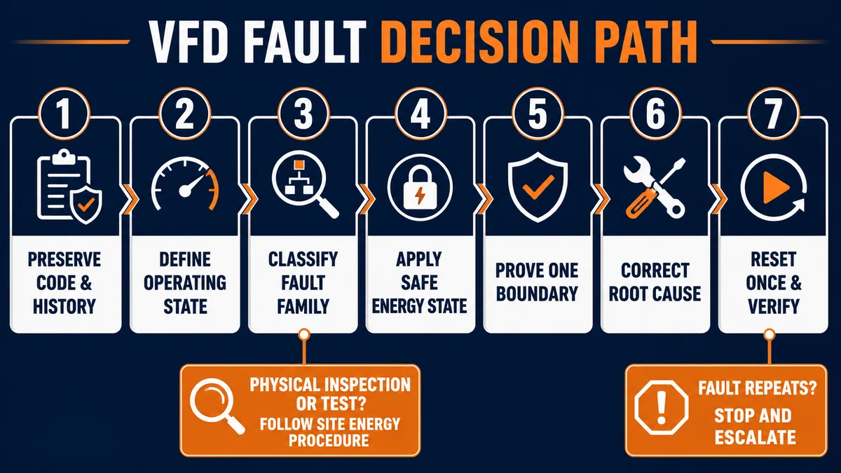
After correction, clear the fault through the documented interface, with the area safe and restart authorized. Confirm the old active condition is gone, the drive reaches the expected non-running state, commands/references are neutral or controlled, and equipment will not auto-start unexpectedly. Run the approved functional test while trending the values that discriminated the cause. If the same fault repeats, stop and escalate rather than widening limits or creating an automatic-reset loop.
Improve PLC and HMI diagnostics for the next event
Retain causal context, not just a fault bit
The PLC should expose drive connected, ready, running, faulted, alarmed and inhibited states; active command source; status and control words; requested and effective reference; actual speed, current and torque; first and active fault; fault time; network quality; and restart inhibit. Map the raw manufacturer code alongside a controlled human-readable description so future code updates do not erase original evidence.
| Diagnostic feature | Minimum implementation | Why it matters |
|---|---|---|
| first-out latch | earliest drive/sequence cause with source timestamp | separates cause from cascade |
| fault queue capture | raw code, port/subcode and order | preserves manufacturer evidence |
| aligned trend | run, reference, status, speed, current, bus, temperature and process | distinguishes control, electrical and load mechanisms |
| reset audit | actor/source, time, prior code and result | detects repeated-reset behavior |
| recurrence counter | code plus operating-state grouping | reveals systematic conditions |
| configuration identity | drive, firmware, parameter set and PLC revision | prevents analysis against wrong manual and settings |
| recovery state | reason automatic restart is inhibited/allowed | makes restart behavior reviewable |
Avoid uncontrolled automatic reset
Automatic reset may be supported for selected nuisance/transient conditions, but it must follow the machine risk assessment, exact product capabilities and approved recovery design. Never blanket-reset ground, short, overcurrent, safety, internal or repeatedly recurring faults. Limit attempts, require the initiating condition to be absent, clear commands as required, log every attempt and block further attempts after recurrence.
Decide between adjustment, repair and replacement
Parameter changes need design evidence
Longer acceleration/deceleration, different current limits, switching frequency, motor thermal values or braking behavior can change production, heat, torque, stopping and protection. Treat changes as controlled engineering changes with before/after parameters, reason, risk impact and regression tests. Never factory-reset a drive as a generic diagnostic action without a verified backup and restoration plan.
Replacement is justified by the exact manual/service process, not simply because the drive is the component displaying the fault. Confirm external supply, motor/cable, cooling, load and configuration evidence first where safe and required. If replacement occurs, control model/options/firmware, parameter source, motor identification, safety configuration, fieldbus mapping, rotation, limits and complete functional validation.
Diagnostic answer map for search and AI-assisted troubleshooting
| Query | Concise answer | Important qualification |
|---|---|---|
| What should I do first on a VFD fault? | Preserve the exact first fault, history, time and operating state before reset. | Apply site energy controls before inspection/testing. |
| Why does a VFD trip on overvoltage? | High incoming line/transients or regenerative energy during deceleration/overhauling can raise the DC bus. | Confirm with the exact manual and aligned bus/speed evidence. |
| Why does a VFD trip on undervoltage? | The DC bus fell below the drive threshold due to line sag/loss, phase/path/precharge or internal causes. | Do not infer cause from the name alone. |
| What causes VFD overcurrent? | Short/ground paths, motor/cable faults, abrupt ramps, wrong motor data, brake/load problems or power-stage issues. | Trip phase and qualified boundary tests discriminate. |
| Why does the VFD show ready but motor not run? | Run/reference source, enable, safety/permissive, control word, output path or load feedback may block result. | Compare requested, effective and physical states. |
| Can I reset a VFD repeatedly? | No; capture evidence, correct the cause, reset once and verify. | Repeated reset can lose evidence and worsen hazard/damage. |
| Does STO make a VFD safe to work on? | STO can address torque-related behavior in its designed safety function but is not proof of electrical isolation. | Follow exact safety manual and energy-control procedure. |
| How do I know if the motor or VFD is faulty? | Isolate the system boundary only under approved procedures and compare supported diagnostics/tests. | Do not insulation-test through connected electronics. |
| Why does a VFD fault only during deceleration? | Regenerative bus rise, stopping demand or load behavior are leading classes. | Review required stop performance before changing ramp/braking. |
| What data should PLC diagnostics store? | Raw first code/subcode, time, state, commands, references, status, speed, current, bus/temp and process context. | Preserve source identity and clock quality. |
Frequently asked questions
What is the difference between a VFD fault, alarm and inhibit?
A fault typically causes a defined stop and requires acknowledgement after its condition is resolved. An alarm reports a condition and may allow operation. An inhibit prevents a state such as start. Exact categories and reactions vary by drive family and configuration.
Should I clear a VFD fault before reading the code?
No. Capture the exact code, subcode/source, fault queue and operating values first. Reset or power cycling can remove the first-out relationship and make an intermittent fault much harder to prove.
Why does my VFD trip immediately when start is commanded?
Leading classes include output short/ground, motor/cable condition, brake or jammed load, abrupt acceleration/boost, incorrect motor configuration, output switching or power-stage fault. Use exact code and trip-time evidence under an approved test plan.
What causes a VFD overvoltage fault when stopping?
The rotating or overhauling load can return energy through the motor and raise the DC bus faster than the system can absorb it. High input voltage or transients are other causes. Confirm with bus, speed and timing trends.
What causes VFD overheating faults?
Blocked filters/heatsink, failed fan, high ambient, inadequate enclosure airflow, excessive load, switching settings or internal thermal problems can contribute. Distinguish drive temperature from motor thermal-overload evidence.
Can I increase the current or overload limit to stop trips?
Not until actual load, motor data/rating, acceleration, cooling, mechanical condition and protection coordination are verified. Raising a limit without evidence can hide a real motor, drive or machine problem.
How can a PLC cause a VFD no-run problem?
The PLC may send the wrong control word, source selection, scale/reference, enable sequence or reset behavior, or its communication may be stale. Compare transmitted request with the drive’s received and effective status.
Is a communication fault always a network problem?
No. Network loss can be primary, or it can occur after the drive/module loses power or faults for another reason. Align drive, adapter, PLC and switch/module timestamps to determine order.
When should a VFD be replaced?
Follow manufacturer service criteria when diagnostics indicate an internal/power-stage/precharge/memory/safety fault, damage is visible, or supported tests exclude external causes. Preserve/verify the complete parameter and safety configuration during replacement.
What proves a VFD repair is complete?
The demonstrated cause is corrected, the original condition no longer exists, one controlled reset succeeds, normal and fault/recovery tests pass, trends stay within approved limits, and as-left configuration/evidence is recorded.
Sources, review scope, and limitations
This guide was reviewed on August 28, 2026. Drive firmware, fault databases and manuals change; use the exact installed catalog/revision and current manufacturer documentation.
- PowerFlex 40P Adjustable Frequency AC Drive User Manual, troubleshooting and fault actions — Rockwell Automation
- PowerFlex 527 User Manual, fault-code summary and troubleshooting — Rockwell Automation
- PowerFlex 6000T Programming Manual, troubleshooting and condition references — Rockwell Automation
- Armor PowerFlex AC Drives User Manual, diagnostics and fault clearing — Rockwell Automation
- SINAMICS G120C List Manual, faults and alarms — Siemens
- SINAMICS G120C Operating Instructions, alarms, faults and communications — Siemens
- ACS580 standard control program firmware manual, fault tracing — ABB
- ACS580-01 current manual index — ABB
- Drive application troubleshooting and PDO/reference interactions — Schneider Electric
- Diagnostics and troubleshooting guidance — Schneider Electric
- 29 CFR 1910.147, control of hazardous energy — OSHA
- Lockout/tagout testing or positioning sequence — OSHA
- Energy-control procedure and control-circuit prohibition — OSHA
The figures are conceptual diagnostic illustrations, not electrical drawings, measurement instructions, safe-work procedures, parameter recommendations, braking designs or authorization to operate equipment. This guide does not authorize opening, probing, disconnecting, insulation-testing, bypassing, resetting, reparameterizing, starting or replacing an installed drive, motor or machine. Qualified, authorized personnel must follow the site hazard assessment, hazardous-energy and electrical safe-work program, required PPE and test instruments, exact manufacturer instructions, machine safety requirements and controlled change/commissioning plan.
Now run it · free to start
Learn a repeatable way to find the fault
Split a stopped machine into input, logic, output and physical response, and take the measurement that proves each stage. Practised on simulated machines. Free to start.
Ownership disclosure: PLC Programming IO and PLC Simulation Software are operated by the same publisher.
PLC Programming IO Editorial Team
Industrial automation education, references, and software testing
The PLC Programming IO Editorial Team publishes sourced industrial-automation education and documents how material is reviewed, tested, and corrected. A team byline means the publisher is responsible for the page; it does not represent a fictional person or imply an engineering licence.
Coverage:
- • PLC programming concepts and examples
- • Vendor software tutorials and comparisons
- • SCADA, HMI, protocols, and instrumentation
- • Training, careers, and reference material
Review standard:
- • Prefer primary and official sources
- • Record software versions when material
- • Separate tested facts from estimates
- • Publish material corrections
Important scope note
This site provides education, not project-specific engineering approval. Safety, code, and compliance decisions require a qualified person with access to the actual machine and jurisdiction.