Mitsubishi FX PLC: Models, Software and Compatibility
Identify a Mitsubishi FX PLC, choose compatible engineering software and cables, compare FX generations, and plan an evidence-led repair or migration without guessing from the family name.
Review status: Editorially reviewed against current Mitsubishi Electric MELSEC-F product, specification, manual, engineering-software, download and legacy-product resources plus IEC, NIST, CISA and OSHA references; exact model code, region, hardware revision, firmware, software build and license, cable, expansion compatibility, terminal assignment, electrical limits, network services, lifecycle, replacement, safety response and site procedure require project-specific verification
Direct answer
Mitsubishi FX is a family of compact MELSEC programmable logic controllers, not one interchangeable PLC. The complete code on the installed CPU—not the word “FX” alone—determines its generation, I/O count, power option, output type, communications, compatible expansions, engineering software and realistic replacement path. Current iQ-F products such as FX5U and FX5UC are normally engineered in GX Works3. Many FX3 projects are associated with GX Works2, while older installations may require GX Developer or a carefully controlled conversion path. Confirm every pairing in the manual and software compatibility information for the exact device and version.
For a new selection, begin with required I/O and electrical characteristics, motion/high-speed needs, communications, expansion count, environment, support horizon and the approved regional catalog. For an existing machine, photograph the full product codes, record LEDs and symptoms, obtain a verified backup, inventory modules and cables, and identify the installed software before changing anything. An FX5 replacement for a legacy FX controller is a migration project, not a guaranteed drop-in swap: dimensions, terminals, I/O behavior, instructions, memory, networks and machine validation can all change.
| If your immediate question is… | Start with… | Evidence needed before acting |
|---|---|---|
| “Which FX PLC is this?” | complete CPU and module labels | clear photos, full codes, hardware revisions and panel drawing |
| “Which software opens it?” | exact CPU generation and project-file type | Mitsubishi software support table, installed build/license and original backup |
| “Which cable do I need?” | exact physical port and interface | connector drawing, port specification and approved cable/adapter code |
| “Can I replace it with FX5?” | installed-system inventory and behavior baseline | conversion guidance, I/O/mounting comparison and witnessed acceptance plan |
| “Why is the machine stopped?” | safe evidence chain from power to process feedback | LED states, diagnostics, program state, input/output evidence and field measurements |
This guide owns the Mitsubishi FX family-selection, identification, software/cable compatibility, lifecycle and migration-decision task. Use the FX3U programming and migration guide for exact FX3U installed-base support, the Mitsubishi PLC programming tutorial for the broader GX Works programming workflow, the FX5U programming guide for an exact FX5U first project, and the FX2N legacy guide for installed FX2N recovery. Those pages answer different intents and remain separate.
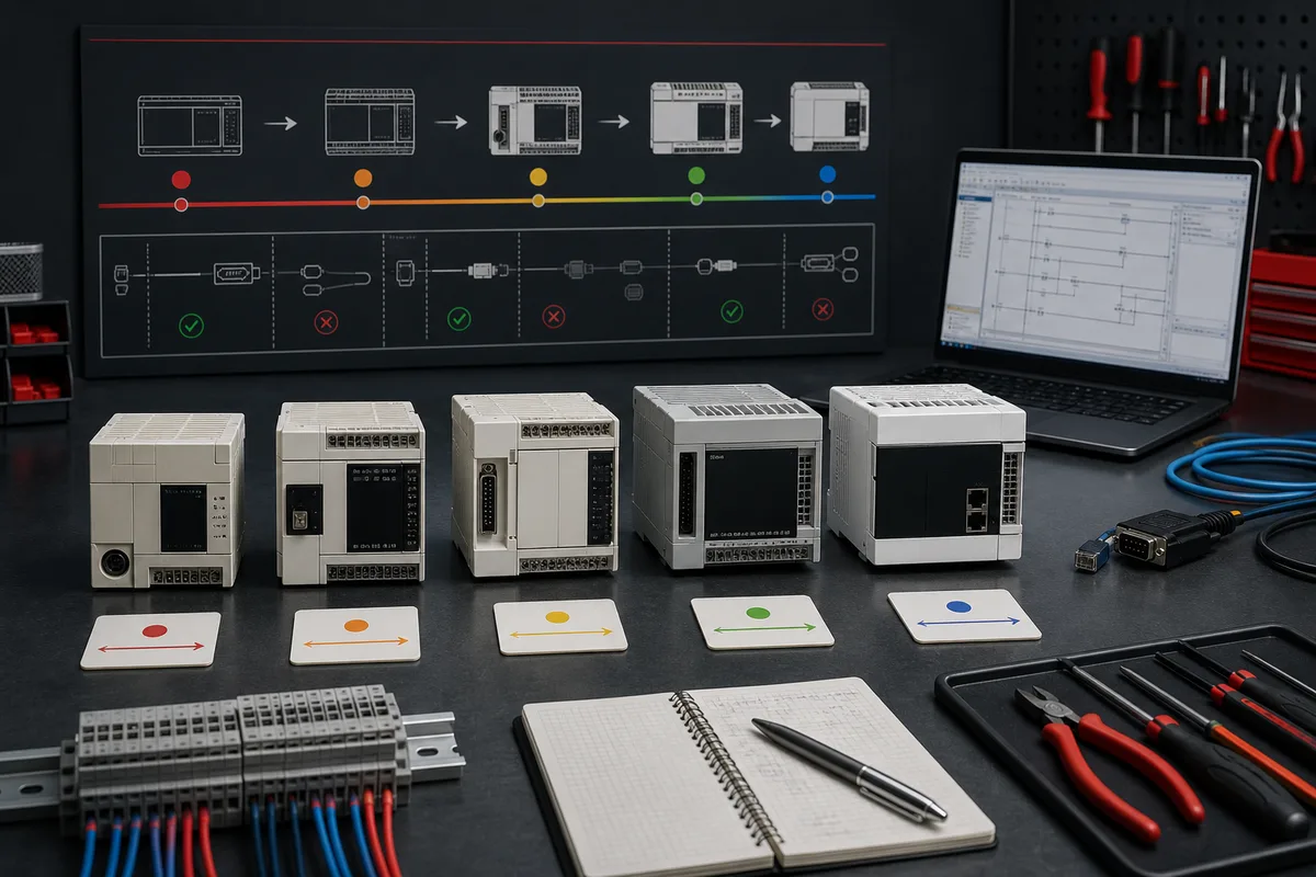
Mitsubishi FX family in one decision table
Read generations as starting points, not substitutions
The broad family can be understood as legacy FX/FX0/FX1/FX2 eras, the later FX3 generation, and the current iQ-F/FX5 generation. That hierarchy is useful for navigating documentation, but it does not make every product within a generation equivalent. Compact brick CPUs, slim modular variants and model-specific extensions differ. Regional availability and lifecycle dates also differ, so a current dated manufacturer page must overrule an undated reseller summary.
| Family area | Typical project situation | Engineering starting point | Decision boundary |
|---|---|---|---|
| original FX, FX0 and early FX1 | old machine with limited records | recover exact label, manual and original project environment | do not assume modern cables, instructions or direct conversion |
| FX1S/FX1N and FX2N/FX2NC | legacy compact machine requiring support | exact legacy manual plus verified software/cable route | replacement may change mounting, terminals, expansions and program behavior |
| FX3G/FX3GC | later compact installed base | GX Works2-era support information for exact CPU | check dated regional lifecycle and supported expansion family |
| FX3U/FX3UC | higher-capability FX3 installed base | GX Works2-era project and exact hardware manuals | inventory adapters, special function blocks, positioning and networks before migration |
| FX5U/FX5UC | current iQ-F control and modernization | GX Works3 and current iQ-F documentation | select exact CPU, I/O variant, network and expansion architecture |
| FX5UJ/other regional iQ-F variants | cost- or region-specific new design | current local catalog and GX Works3 support information | never infer identical limits from a similar FX5 enclosure |
The official MELSEC-F product and specification pages are the best entry points for currently offered products. The manufacturer’s legacy pages are the better starting point for discontinued systems. A procurement marketplace may help locate a spare, but it is weak evidence for compatibility, authenticity, repair status or future support.
Use a requirements gate before choosing a model
A good FX selection record states the quantity and electrical type of digital inputs and outputs; analog ranges and resolution; relay or transistor output needs; sink/source convention; pulse, encoder and positioning requirements; scan and response expectations; serial, Ethernet and field-network roles; local and remote expansion; environmental ratings; approved power architecture; maintainability; cybersecurity zoning; and safety functions that must remain independent or use an approved safety system.
| Requirement group | Questions that change the CPU choice | Evidence to retain |
|---|---|---|
| base I/O | how many points, which voltage, which output technology, which commons? | approved I/O schedule and electrical drawings |
| motion/high-speed | pulse train, counters, interrupts, axes, synchronization? | load/motion study and exact function specifications |
| analog/process | voltage/current, RTD/thermocouple, resolution, update and isolation? | instrument list, signal ranges and module manual |
| communications | protocol, client/server or controller/device role, ports and redundancy? | network architecture and compatibility records |
| expansion | present and future modules, bus limits, addressing and power budget? | configured station list and manufacturer selection result |
| environment | temperature, vibration, enclosure, EMC, hazardous area and approvals? | risk assessment and product certificates |
| lifecycle | planned service life, local availability, spares and migration window? | dated manufacturer lifecycle evidence and spares policy |
Identify the exact FX PLC before downloading software
Capture the complete product identity
Record the CPU code exactly, including suffixes. Then record every attached module, adapter, communication board, terminal conversion unit and operator interface. Photograph the front and side labels, port covers, terminal numbers and panel overview. If the machine is energized and access is authorized, record power, run, error, battery and communication LED states without defeating guards or reaching into exposed hazards.
The complete identity matters because apparently small suffixes can encode I/O quantity, mains or DC supply, relay or transistor output and form factor. An FX5U-32 controller is not interchangeable with every other 32-point unit; output polarity, power, high-speed functions and expansion layout still need confirmation. A vague inventory such as “Mitsubishi FX PLC, 24 V” is not enough to choose software, wiring or a replacement.
| Record | Good example of the evidence form | Why it matters |
|---|---|---|
| CPU | full printed catalog string and serial/revision where exposed | identifies manuals, software support and base I/O |
| extensions | full code in physical left-to-right order | reveals I/O map, specialty functions and migration scope |
| ports/adapters | connector and adapter codes, not “serial cable” | separates programming, RS-422/485, USB and Ethernet paths |
| project | original file, last modification, comments and symbol state | establishes whether a maintainable source exists |
| software | product name, exact version/build and license state | prevents changing a project with an incompatible environment |
| machine state | switch positions, LEDs, diagnostics and first-out event | preserves evidence before a reset changes the story |
Distinguish labels from project discovery
Do not start by probing random ports or choosing an auto-detect option. First identify the physical interface from the manual. A round connector, mini-DIN, USB connector and Ethernet jack can represent very different electrical and protocol requirements. An unverified passive pin adapter can damage a port or computer even when the connectors fit.
If no backup exists, treat upload as a controlled recovery operation. Establish safe machine state and authorization; preserve the current PC and software environment if available; document communication settings; read without writing; save a raw recovered copy; duplicate it for analysis; and compare it with drawings and behavior. Passwords, missing comments, unsupported project formats or locked blocks are project facts to escalate, not obstacles to bypass.
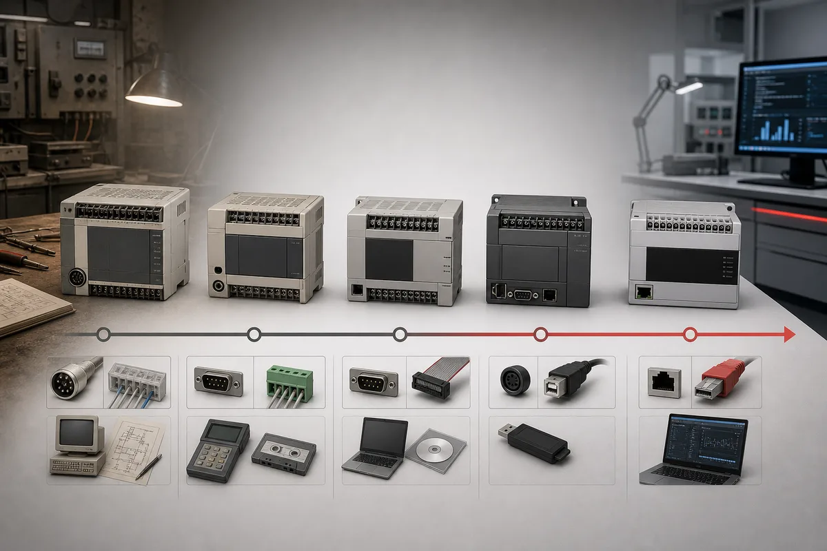
Choose Mitsubishi FX programming software correctly
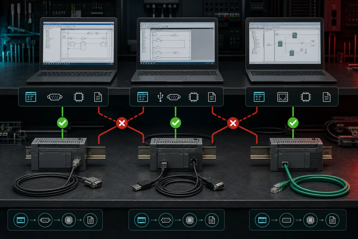
GX Works3 is the current iQ-F starting point
Mitsubishi Electric positions GX Works3 as the engineering environment for current MELSEC iQ-R and iQ-F controllers. For an FX5U, FX5UC or other supported iQ-F CPU, begin with GX Works3, then verify that the installed release supports the exact CPU and firmware. A project created or upgraded in a newer release may not open or behave identically in an older engineering station. Record the application version before conversion and keep an untouched source copy.
GX Works3 can provide structured project organization, parameter configuration, labels, monitoring, diagnostics and simulation-related functions, but tool availability does not prove the real machine. The desktop simulation model does not reproduce every specialty module, network, drive, scan interaction, electrical fault, motion load or safety function. Use simulation for logic evidence, then validate representative hardware and the approved machine.
GX Works2 remains relevant to supported FX3 installations
GX Works2 is an important environment for many FX3 projects and other supported MELSEC families. “FX3 uses GX Works2” is still only a starting rule: exact CPU support, software release, special module configuration and project origin must be checked. An older project may have been maintained in GX Developer, imported, or depend on devices and instructions whose conversion needs review.
GX Developer is a legacy environment, not the preferred default for a new design. Preserve a known-working virtual or physical maintenance environment when lawful and supported by the organization. Record installation media, license entitlement, OS compatibility, communication drivers and cables. Do not download executables from unverified file-sharing sites; use Mitsubishi Electric’s official software and download portals or an authorized channel.
| Exact situation | Likely starting environment | Required verification before connect/download |
|---|---|---|
| FX5U/FX5UC current project | GX Works3 | CPU support, firmware compatibility, project version and license |
| supported FX3 project | GX Works2 | exact CPU/module support, version and original project provenance |
| older FX1/FX2 project | legacy environment or controlled import | manual, original format, cable/driver and conversion report |
| unknown installed CPU | none yet | full product identity and official support table first |
| replacement project | target environment plus preserved source environment | conversion route, unsupported items and acceptance baseline |
Live mini-lab
Try it: press START, then STOP
A stop-dominant seal-in rung: START latches the motor output through its own contact, and STOP breaks the circuit.
Watch the output lamp: it stays on after START until you press STOP.
Free to start · runs in your browserOpens plcsimulationsoftware.com — same team
Select the programming connection and cable
Match the physical layer and protocol separately
“Mitsubishi FX programming cable” is too broad for procurement. Older FX systems may use a manufacturer-specific serial programming interface and cable. Later models and adapters may expose USB, Ethernet, RS-422 or RS-485 connections. Some ports are intended for peripherals or networks rather than direct programming. The connector shape alone cannot tell you voltage levels, pinout or protocol.
Use this controlled chain: exact CPU/adapter code → port name in the hardware manual → supported programming method → official cable/adapter specification → supported OS driver → communication settings → read-only connection test. If Ethernet is used, record the approved network zone, computer address, CPU address, transport and routing. Never scan an operational controls network broadly merely to find a PLC.
| Connection class | Verify before use | Common false assumption |
|---|---|---|
| legacy serial programming port | official cable code, pinout/electrical interface and driver | any USB-to-serial adapter with a fitting plug will work |
| USB device port | supported CPU, cable type, vendor driver and OS | USB connector guarantees driverless access |
| Ethernet programming | CPU/adapter supports it, IP route, protocol and security approval | an RJ45 jack means the PLC will appear automatically |
| RS-422/RS-485 network port | role, pinout, termination, bias, station and protocol | serial network terminals are always the programming port |
| third-party cable | documented equivalence, isolation/protection and trusted driver | marketplace compatibility wording is engineering evidence |
Before the first connection, disable automatic project writes and compare the offline target setting with the physical CPU. Read diagnostics and parameters before downloading. A successful online connection proves communication only; it does not prove that the offline project is the running source of truth.
Understand FX I/O without unsafe shortcuts
Decode inputs and outputs from exact manuals
An input point is not simply “24 volts,” and an output point is not simply “on.” Establish the supply, common, polarity, threshold, isolation group, protection and field device type. Establish whether outputs are relay or transistor, and for transistor variants confirm sink/source behavior, permitted load, external supply, leakage, protection and switching constraints. Use the exact terminal diagram for the complete CPU suffix and extension module.
Relay outputs can switch different load types within published ratings but have finite mechanical/electrical life and slower operation. Transistor outputs suit faster DC switching but have polarity and semiconductor limits. Neither should be assumed capable of directly driving every contactor, solenoid, lamp or inductive load. The machine design may require interposing relays, suppression, fusing and separation. Safety-related loads require the approved safety architecture; standard PLC logic and a standard output are not a safety function merely because the code contains an emergency-stop contact.
Keep software addresses tied to physical evidence
FX documentation commonly uses device prefixes such as X for inputs, Y for outputs, M for internal relays and D for data registers, but address representation and available ranges depend on the CPU and tool. Some Mitsubishi contexts show input/output numbers using octal progression. Do not teach or troubleshoot a universal address formula from memory. Use the device-memory and I/O-assignment sections for the exact CPU, then reconcile the project, module layout and terminal drawing.
| Layer | Question | Evidence that closes it |
|---|---|---|
| physical device | is the sensor/load powered and wired to the correct common? | approved drawing and controlled measurement |
| terminal | does the field state reach the intended terminal? | terminal identifier and measured state within manual limits |
| input/output circuit | does the corresponding hardware LED/state change? | exact module manual and diagnostic observation |
| logical device | does the expected X/Y or mapped variable change online? |
project cross-reference and online trace |
| application | are mode, permissive, sequence and interlocks satisfied? | first-false logic path and retained first-out evidence |
| actuator/process | did the command create verified feedback in time? | output evidence, field feedback, timer and process response |
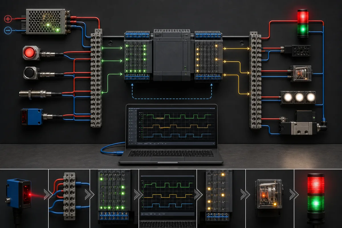
Build a first FX project as an acceptance test
Separate the learning model from the real machine
A first project should be small enough to predict completely. Define one input request, one permissive, one command, one physical output in the test design, one feedback, one timeout and one reset rule. Make startup safe, require deliberate mode selection, and avoid retentive behavior until it is explicitly justified. The objective is not merely to energize an output; it is to prove the entire request-to-feedback contract.
For a training model, a generic sequence can be represented as:
Permit := ModeAuto AND GuardingHealthy AND NoActiveFault;
RunCommand := RunRequest AND Permit AND NOT StopRequest;

IF RunCommand AND NOT RunningFeedback FOR FeedbackTimeout THEN
    FirstOut := FeedbackMissing;
    RunCommand := FALSE;
END_IF;

ResetAccepted := ResetRequest
              AND NOT RunRequest
              AND SafeResetConditions;
Run Structured Text in the simulator
This is not vendor-ready machine safety code. Exact scan behavior, device retention, instruction semantics, physical I/O, timers, forcing and restart requirements must be verified in the chosen FX CPU and approved design. The useful habit is to write predicted tests before download.
| Acceptance case | Controlled stimulus | Expected evidence |
|---|---|---|
| cold start | power or simulated startup | outputs remain in defined safe state; no automatic restart |
| valid start | healthy permissives plus run request | request, command and feedback occur in declared order |
| missing permissive | remove one permission before start | first false condition is visible and command remains false |
| feedback timeout | command without simulated/controlled feedback | timer expires, first-out is retained and command follows defined response |
| stop | issue ordinary stop | command clears and feedback falls within allowed time |
| reset | remove initiating demand, restore safe conditions, request reset | fault clears only under the declared reset rules |
| power recovery | restore after interrupted sequence | behavior matches the restart risk assessment |
Use online monitoring to observe, not to replace design evidence. Forces and writes can move machinery, override field conditions or hide wiring faults. Apply them only under the site’s authorized test procedure, with affected personnel and energy controls addressed.
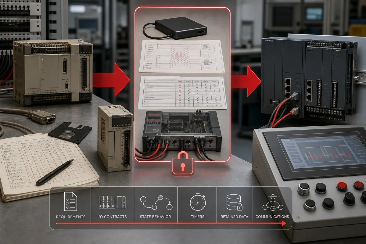
Plan an FX3 or legacy FX migration to FX5
Treat conversion as requirements recovery
Mitsubishi Electric’s US legacy pages explicitly state that some older FX products are succeeded by FX5U/FX5UC while warning that the successor is not necessarily a direct drop-in and that program changes, wiring changes or both may be required. That is the correct migration mindset. “Succeeded by” points to the current family; it does not certify terminal equivalence or unchanged machine behavior.
Recover the as-built system before selecting the target. Capture the program with comments if available; CPU parameters; retentive ranges; clock and battery dependencies; I/O and expansion order; analog scaling; pulse and counter functions; interrupt/event behavior; serial protocols; network adapters; HMI/SCADA addresses; recipes; alarms; maintenance modes; spare points; terminal conversion hardware; enclosure dimensions; and actual sequence timing. Resolve discrepancies between drawing, source and plant behavior as explicit engineering decisions.
Create a conversion exception register
Automated conversion is a useful translator, not an acceptance test. Review every warning and every changed or unsupported instruction. Compare device ranges, retentive memory, scan timing, numeric representation, timers/counters, special relays/registers, high-speed functions, communications, module configuration and startup behavior. Turn each difference into an owner, disposition and test.
| Migration evidence | Minimum content | Reject the migration gate when… |
|---|---|---|
| installed inventory | exact CPU, modules, adapters, terminals and peripherals | any unidentified item still affects operation |
| source baseline | checksum/version, comments, parameters and trusted backup | the running program cannot be reconciled with the source |
| I/O cross-reference | old terminal/address to new terminal/address and electrical type | only like-for-like tag names were compared |
| conversion report | warnings, unsupported items, manual edits and reviewers | unresolved warnings are treated as harmless |
| behavior tests | startup, modes, sequences, faults, restart and communications | only normal production was tested |
| rollback plan | preserved old hardware/source, change window and decision point | rollback depends on unverified spare equipment |
Troubleshoot a Mitsubishi FX PLC by boundaries
Preserve the first evidence before resetting
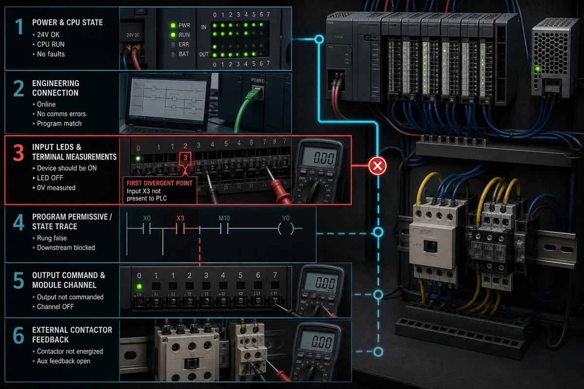
Begin outside the program: clarify the symptom, time, last known good operation, recent work and affected operating mode. Establish safe access. Capture the CPU mode and LEDs, HMI message, drive/remote-I/O state, first-out alarm and communication indicators. A reset may make the machine run, but it can erase the evidence required to prevent recurrence.
Then move through boundaries in order: incoming/control power → CPU state and diagnostics → local/extension I/O health → input request → mode/permissive chain → sequence step → output command → module/terminal electrical state → contactor/valve/drive → process feedback. Stop at the first mismatch between expected and observed state. Do not rewrite logic merely because a coil is false; determine which required condition is false and why.
| Symptom | First checks | Evidence that changes the next action |
|---|---|---|
| no power LED | approved supply source, protection and CPU supply terminals | measured supply inside or outside exact manual limits |
| CPU error | error LED pattern/code, diagnostic buffer and recent changes | manufacturer diagnostic meaning for exact CPU/firmware |
| cannot connect | exact CPU/port/cable/driver/software and network route | physical link, correct interface, then protocol response |
| input LED off | field power, common, sensor and terminal voltage | valid signal reaches terminal but module state remains false |
| output LED on, load off | output type, supply/common, protection and load circuit | command exists but electrical output or field path is open |
| intermittent stop | first-out, power quality, connector state, temperature and network age | timestamped correlation identifies first failed boundary |
| program runs differently after replacement | conversion exceptions, parameters, retained values and scan-dependent logic | repeatable divergence from the preserved behavior baseline |
Keep cybersecurity and safety in the diagnostic plan
NIST SP 800-82 Rev. 3 recommends managing operational technology with its performance, reliability and safety requirements in mind. Treat engineering workstations, removable media, downloaded project files and temporary network routes as controlled assets. Use authorized software sources, preserve hashes/backups, minimize access, and remove temporary connectivity after the job. Check CISA advisories and the manufacturer’s security information for relevant products and engineering tools.
For hazardous energy and exposed electrical work, follow the site procedure and applicable law. In the United States, OSHA’s hazardous-energy control and electrical work requirements are primary references; other jurisdictions have their own rules. Online monitoring, forces and parameter changes are not administrative conveniences when they can initiate motion or change a safe state.
FX lifecycle, spares and documentation control
Use dated regional manufacturer notices
Lifecycle is not a permanent property copied from a search snippet. At the review date, Mitsubishi Electric’s global MELSEC-F feature page publishes future order-acceptance and production-discontinuation dates for specific FX3 families, while regional legacy pages describe already discontinued products and repair periods. These are dated planning inputs. Recheck the exact regional notice at procurement or change approval because availability, services and successor guidance can differ by market and can change.
A spare strategy should record authenticity, storage environment, battery policy where applicable, firmware/hardware revision, proven program load, compatible modules and a periodic test. An untested used CPU is inventory, not resilience. For a business-critical legacy machine, preserve both a support path and a funded migration trigger: repeated failures, unavailable parts, unsupported engineering environment, cybersecurity exposure or planned plant expansion may each justify conversion before an emergency.
Make the manual set part of the asset
Download manuals from Mitsubishi Electric’s official portal using the exact family and model. Preserve the document number, revision and access date with the project. The minimum set typically includes hardware/user manuals, programming/device-memory references, communication/manuals for each adapter, special-module manuals, engineering-software support information and any conversion guidance. A distributor summary is not a substitute for terminal tables or operating limits.
| Controlled asset record | Why operations needs it |
|---|---|
| full bill of materials and revisions | selects correct spares and manuals |
| software installer/build and entitlement | restores a lawful maintainable engineering station |
| verified source and last-known-good backup | prevents an emergency upload/download guess |
| cable/driver/network record | restores access without improvised interfaces |
| manual numbers and lifecycle evidence | supports safe maintenance and timely migration |
| acceptance and rollback tests | proves a repair or conversion preserved intended behavior |
Diagnostic answer map
| Question people ask search engines or AI assistants | Concise answer | Verification boundary |
|---|---|---|
| What is a Mitsubishi FX PLC? | A compact MELSEC controller family spanning multiple legacy and current generations. | identify the complete CPU code before selecting software or parts |
| Is FX5U a replacement for FX3U or FX2N? | It is a common current migration direction, not a universal drop-in replacement. | compare wiring, dimensions, modules, instructions, memory, networks and behavior |
| Which software programs Mitsubishi FX? | GX Works3 is the current iQ-F starting point; many FX3 systems use GX Works2; older systems may need controlled legacy support. | verify exact CPU, firmware, project format and software build |
| Can GX Works3 open an old FX project? | Some migration/import workflows exist, but opening or conversion does not prove equivalence. | preserve the source, review the conversion report and retest behavior |
| How do I identify relay versus transistor outputs? | Read the complete CPU/module suffix and exact hardware manual. | never infer output type from enclosure appearance |
| Why is an FX output LED on but the device off? | Logic command may exist while field supply, protection, terminal, wiring or load feedback has failed. | trace voltage/current under an authorized procedure using the exact diagram |
| Where can I download Mitsubishi FX manuals? | Use Mitsubishi Electric’s official documentation/download portal and exact model search. | retain document number, revision, region and access date |
| Is a simulator enough to commission an FX PLC? | No; it can prove bounded logic but not every I/O, module, network, motion or machine hazard. | repeat controlled tests on representative hardware and the approved machine |
Frequently asked questions
What does FX mean on a Mitsubishi PLC?
FX identifies Mitsubishi Electric’s compact MELSEC-F controller family. It does not specify one CPU or a complete compatibility set. FX1, FX2, FX3 and FX5-era controllers span different engineering environments, memory, I/O, extensions and lifecycle states. Record the full code and suffix from the label before choosing manuals, cables, software or a replacement.
Which software is used for a Mitsubishi FX PLC?
GX Works3 is the normal current starting point for supported MELSEC iQ-F CPUs such as FX5U/FX5UC. Many supported FX3 installations use GX Works2. Older systems may involve GX Developer or a controlled import/conversion workflow. Confirm the exact CPU, firmware, project origin and tool version in current Mitsubishi documentation rather than relying on the family name.
Can GX Works3 program every Mitsubishi FX PLC?
No. GX Works3 targets current supported families and does not make every legacy FX CPU a native target. An old project may require GX Works2, a legacy environment or conversion into a different target. Preserve the original source and environment, use the manufacturer’s support information, and treat conversion warnings as test requirements.
What is the difference between FX3U and FX5U?
They belong to different generations with different CPU architecture, engineering workflow, device capabilities, built-in functions and compatible extensions. FX5U is a current iQ-F migration direction for many FX3 applications, but it is not universally terminal-, module- or program-equivalent. Build an exact old-versus-new comparison from official manuals and the installed machine.
Is FX5U a drop-in replacement for FX2N?
Do not assume so. Mitsubishi’s legacy guidance points to newer FX5 products while warning that programs, wiring or both may need changes. Inventory every module and terminal, recover the program and parameters, review converted instructions/device ranges, and test startup, sequences, faults, communications and restart before acceptance.
How do I find the correct Mitsubishi FX programming cable?
Identify the exact CPU and any communication adapter, then use its hardware/manual port description to select the supported programming interface and official cable or documented equivalent. Verify electrical interface, connector, driver, operating system and engineering-software settings. Connector fit alone is not evidence that a cable is safe or compatible.
Are Mitsubishi FX input and output addresses octal?
Some FX documentation and project contexts represent X and Y devices using octal-style progression, but available ranges and assignment rules depend on the exact CPU, extensions and engineering tool. Use the device-memory and I/O-assignment chapters for that model. Never convert or rewire solely from a remembered universal rule.
Where should I download Mitsubishi FX software and manuals?
Use Mitsubishi Electric’s official software/document download portals or an authorized regional channel. Search by the full product code and retain the document number, revision, software version, license evidence and access date. Avoid unverified executable archives and anonymous cable drivers because they introduce compatibility, security and support risk.
How do I troubleshoot a Mitsubishi FX PLC that will not run?
Make the machine safe, preserve CPU LEDs and diagnostics, then trace power, CPU state, modules, input request, mode/permissives, sequence, output command, terminal state, actuator and process feedback. Stop at the first mismatch. Avoid resetting, forcing or rewriting until the original evidence and authorization are secured.
Can I use a browser PLC simulator before buying an FX controller?
Yes, for vendor-neutral control concepts such as request/permissive/command/feedback, timers, interlocks and fault evidence. It cannot prove exact Mitsubishi instruction behavior, device retention, cable compatibility, module timing, electrical characteristics, networking, motion or safety. Transfer the tested requirement to the exact FX target and validate it independently.
Practical next step
Create a one-page FX identity and decision record before purchasing, connecting or replacing anything. Include full CPU/module codes, region, software/project version, port/cable, I/O electrical types, networks, lifecycle evidence, backup status and the immediate decision. For a fault, add the first failed boundary. For a migration, add every conversion exception and its acceptance test. That record turns an ambiguous “Mitsubishi FX” search into a controlled engineering task.
Sources, review scope, and limitations
This guide was reviewed on 30 August 2026. Official manufacturer pages are used for family roles, engineering software, documentation and lifecycle direction. Lifecycle and regional availability must be rechecked at the time of action. Product manuals and approved project documents govern the installed system.
- Mitsubishi Electric — MELSEC-F series product index
- Mitsubishi Electric — MELSEC-F features and lifecycle notices
- Mitsubishi Electric — MELSEC-F specification search
- Mitsubishi Electric — FX series English manual index
- Mitsubishi Electric — PLC engineering software index
- Mitsubishi Electric — GX Works3 product information
- Mitsubishi Electric — GX Works2 product information
- Mitsubishi Electric — official software download portal
- Mitsubishi Electric — GX Works2 simulation and debugging functions
- Mitsubishi Electric — GX Works3 catalog
- Mitsubishi Electric — original FX legacy support
- Mitsubishi Electric — FX2N and FX2NC legacy support
- Mitsubishi Electric — FX3U hardware manual
- Mitsubishi Electric — MELSEC-F family catalog
- Mitsubishi Electric — MELSEC-F selection guide
- IEC — IEC 61131-3:2025 programmable-controller languages
- NIST — SP 800-82 Rev. 3, Guide to Operational Technology Security
- CISA — Industrial Control Systems advisories
- OSHA — Control of hazardous energy (lockout/tagout)
- OSHA — Electrical safety-related work practices
The diagrams are original, brand-neutral teaching illustrations. They do not reproduce Mitsubishi product fronts, terminal arrangements or wiring and must not be used as installation drawings. Product names identify compatibility research only; PLC Programming IO is not Mitsubishi Electric and does not represent manufacturer approval.
Now run it · free to start
Practise Mitsubishi-style PLC logic in your browser
Work X/Y/M/D devices, latches, timers and counters without GX Works. An independent learning tool — free to start.
Ownership disclosure: PLC Programming IO and PLC Simulation Software are operated by the same publisher.
PLC Programming IO Editorial Team
Industrial automation education, references, and software testing
The PLC Programming IO Editorial Team publishes sourced industrial-automation education and documents how material is reviewed, tested, and corrected. A team byline means the publisher is responsible for the page; it does not represent a fictional person or imply an engineering licence.
Coverage:
- • PLC programming concepts and examples
- • Vendor software tutorials and comparisons
- • SCADA, HMI, protocols, and instrumentation
- • Training, careers, and reference material
Review standard:
- • Prefer primary and official sources
- • Record software versions when material
- • Separate tested facts from estimates
- • Publish material corrections
Important scope note
This site provides education, not project-specific engineering approval. Safety, code, and compliance decisions require a qualified person with access to the actual machine and jurisdiction.