PLC CPU, Power Supply and Memory Troubleshooting
Diagnose PLC CPU state, control and backplane power, memory and storage faults without erasing the evidence or replacing the wrong component.
Review status: Editorially reviewed against current Siemens S7-1500, Rockwell ControlLogix 5590/5580, Schneider Modicon M580 and Mitsubishi MELSEC iQ-R manuals and official OSHA electrical de-energization guidance; exact status patterns, power budgets, test points, memory behavior, reset procedures, environmental limits and safety functions remain product-, revision- and site-specific
Direct answer
Troubleshoot a PLC CPU, power or memory fault by preserving evidence and locating the first failed boundary before restarting, clearing memory or replacing hardware. First record the exact controller display and LED pattern, operating mode, timestamp, diagnostic buffer and fault code, active forces or online edits, project and firmware identity, and memory/storage status. Then classify the controller as indicators off, starting/initializing, stopped/program mode, running with diagnostics, or faulted/inoperable.
Separate five physical and logical boundaries: source/control-power input, power-supply output/status, backplane capacity and module demand, CPU startup/diagnostics, and memory/storage/project identity. Also separate controller/backplane power from field or load supply; a CPU can remain in RUN while sensors, remote modules or output loads lose their separate supply. Conversely, a module or backplane power-budget problem can prevent startup even when the external supply indicator appears normal.
Do not use LEDs as proof of electrical de-energization. Do not press a memory-clear or factory-reset control until the installed manual, authorization, recovery image and rollback are confirmed. A reset can erase the application, retained values, configuration and fault evidence. A removable card or nonvolatile image can also load an older project and overwrite newer logic or data. Choose recovery only after the fault class and data consequences are understood.
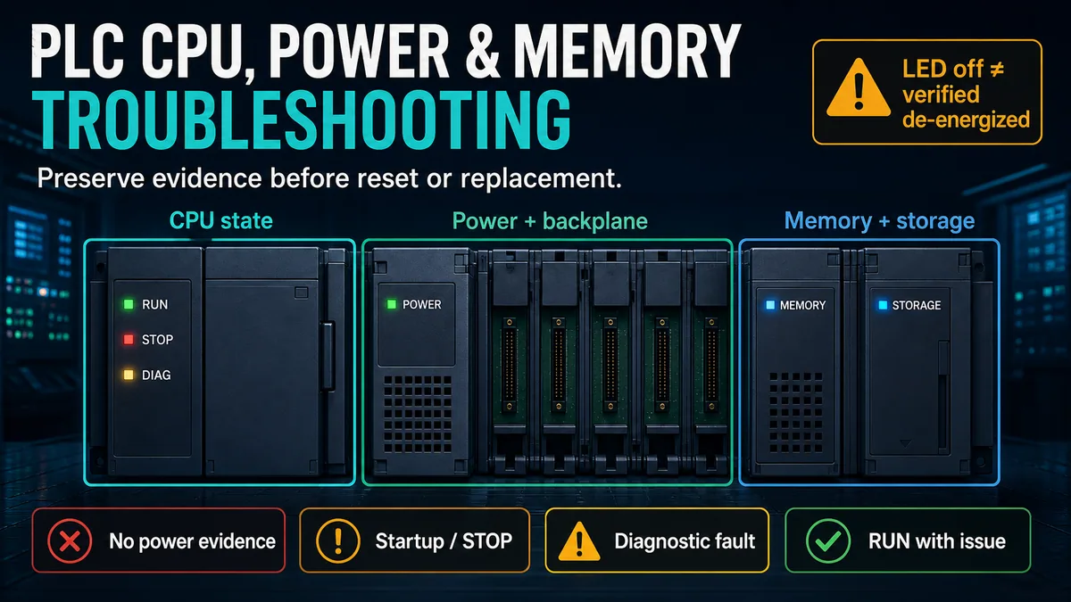
Establish the safety and recovery boundary
Treat the controller as part of an energized machine or process
A PLC cabinet may contain hazardous voltages, stored energy, multiple sources, backfeeds and remotely controlled equipment. Follow the facility's energy-control, electrical safe-work, arc-flash, functional-safety and process procedures. OSHA's electrical work-practice rule states that push buttons, selector switches and interlocks are not the sole means of de-energization; qualified-person test equipment is required where the rule applies to verify exposed circuit parts are de-energized.
An extinguished power LED does not prove absence of voltage at the supply input, another circuit, a load-side backfeed or stored-energy component. Conversely, an illuminated CPU LED does not establish that field outputs are safe. Use the site's approved isolation and verification process before exposing, removing or measuring components.
| Safety question | Evidence/authorization required | Failure prevented |
|---|---|---|
| what equipment can move or energize? | process state, energy sources, interlocks, stored energy and affected personnel | unexpected motion or release during restart |
| which parts remain energized? | current drawings, source tracing and qualified verification | shock, arc and backfeed assumptions |
| what does the application do after recovery? | startup sequence, output initialization, retained state and operator procedure | automatic restart or stale command reuse |
| is this a safety controller or safety application? | validated safety procedure and product manual | unsafe use of general PLC reset guidance |
| who owns the project and backup? | version control, signatures/hashes, approver and restore plan | loading the wrong application |
| can evidence be preserved before power removal? | approved online/web diagnostics, screenshots and exports | destroying first-out fault evidence |
Define rollback before any reset, download or firmware action
Record the installed hardware catalog/revision, controller serial/identity, firmware, application name/revision, last validated backup, communication configuration, memory-card contents/status, retentive-data requirements and exact recovery acceptance tests. Confirm that engineering software and firmware tools are compatible and trusted. Do not improvise a firmware update while power is unstable or a storage fault is active.
A project restore can be as consequential as a hardware change. It may alter outputs, recipes, setpoints, network identity, I/O ownership, safety signatures or retained values. Verify what the particular controller saves and loads, when a nonvolatile image loads, and which data comes from the image rather than current runtime memory.
Classify the controller state before naming the fault
Read the complete pattern and sequence
One indicator rarely identifies a cause. Siemens S7-1500 manuals combine RUN/STOP, ERROR and MAINT state; the same CPU may show startup, STOP, RUN, diagnostic event, active force job, bad configuration, memory-card problem or firmware activity through different combinations. Rockwell controllers combine a status display with RUN, FORCE, SD and module-status indicators; its 5580 documentation warns that indicators provide general rather than detailed safety diagnostics.
Record colors, steady/flashing pattern, display text, sequence from power application, duration and changes. Use the exact catalog number and firmware manual. A controller that remains in STOP after a normal startup is different from one looping through initialization, one executing normally with an I/O diagnostic, and one powered but inoperable.
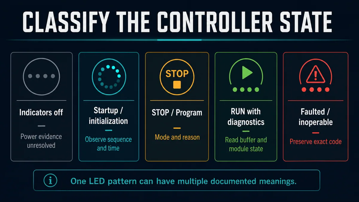
| Observed state | What it establishes | First decisive checks | Do not assume |
|---|---|---|---|
| all indicators/display off | no visible controller status is available | safety boundary, source, supply input/output/status and backplane path | cabinet is de-energized or CPU is failed |
| repeating startup/initialization | startup is not completing normally | timeline, power stability/budget, storage/project and startup fault buffer | power cycle will cure the cause |
| STOP/Program | user tasks are not executing normally | mode switch/software mode, reason, fault, startup conditions and project | hardware is defective |
| RUN with diagnostic | CPU executes but a diagnostic/maintenance/force condition exists | diagnostic buffer, module state, forces, task and application evidence | green RUN means all I/O/processes are healthy |
| faulted but online | engineering diagnostics may still be retrievable | exact major/minor/nonrecoverable code and first-out event | clear/reset is safe before export |
| powered but inoperable/offline | controller cannot provide normal online access | display/LED manual, power/thermal/firmware/storage evidence and trusted support path | application is simply missing |
Separate mode, fault and machine state
Controller RUN/STOP mode describes program execution state, not whether the machine is safe, ready or moving. A controller can be in RUN with outputs inhibited, an I/O station failed, forces active or application interlocks blocking operation. A controller can be in STOP while devices retain or enter product-specific states. Record the physical mode switch, software-requested mode, task state, I/O status and process state independently.
The next page in the portfolio, PLC program debugging, owns online monitoring, forcing and traces. This guide records forces and online edits because they change recovery risk; it does not treat them as a CPU or memory repair.
Preserve diagnostic evidence before recovery
Export the first-out buffer and project identity
Read the controller's diagnostic buffer, major/minor fault tabs, event history, web diagnostics and module status while evidence is available. Record exact code, subcode, text, module/slot, task/program/routine, timestamp and controller state before/after. If clocks are not synchronized, note the offset. Photograph the display/LEDs with timestamps where permitted, then export machine-readable records if the product supports it.
Compare the online controller with the version-controlled project: name, controller type, firmware, serial/identity binding, checksum/signature, safety signature where applicable, online edits, forces, nonvolatile image revision and last download/change time. Do not upload from an unknown controller and immediately call that upload the validated master.
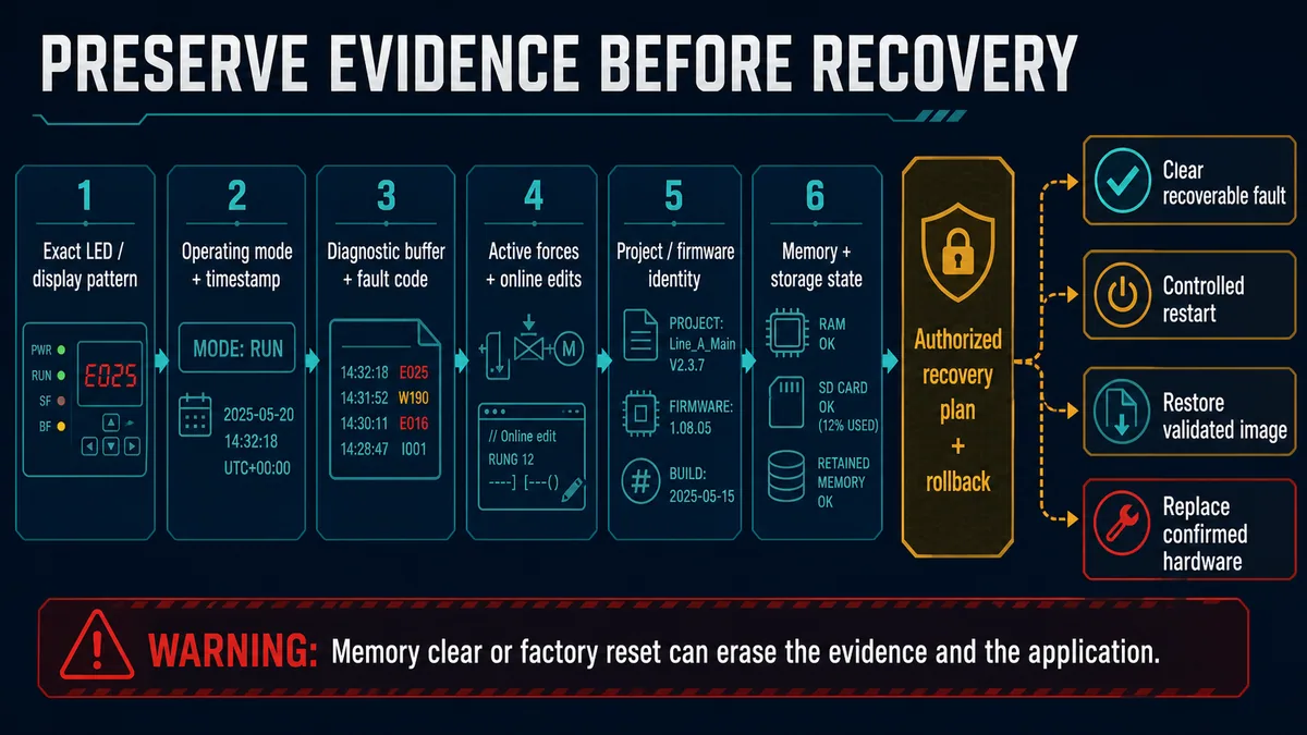
| Evidence surface | Minimum record | Why it can disappear |
|---|---|---|
| front display and indicators | full pattern, text, time sequence and catalog number | restart or state change alters it |
| diagnostic/fault buffer | original code/text, first timestamp, source/module and preceding events | clear, memory reset, log rollover or replacement |
| operating state | hardware/software mode, tasks, I/O and process state | reset/download changes execution context |
| project identity | version/hash, online/offline comparison, firmware and last change | load/restore can overwrite current image |
| forces and edits | enabled forces, forced points, pending/accepted edits | download/reset can remove or hide them |
| memory/storage | capacity/status, access/lock state, configured power-up load and image revision | card removal, format or image load changes state |
| power/environment | source/supply/backplane status, load budget, temperature/ventilation and event time | reboot removes dynamic conditions |
Distinguish observed, decoded and inferred facts
“RUN LED green and ERROR flashing” is observed. “Manual says a diagnostic event is pending for this combination” is decoded. “Power supply is failing” is an inference that still requires supporting evidence. Keep those levels separate in the incident record so later changes do not turn a hypothesis into remembered fact.
If a controller is completely inaccessible, preserve upstream evidence: power-supply/rack status, managed-switch link history, redundant-controller partner status, HMI alarms, historian gaps, environmental events and photographs. Lack of online diagnostics does not authorize an immediate reset.
Separate source, supply, backplane and field power
Trace the designed power path by boundary
Identify the incoming source and disconnect, controller power-supply input, power-supply output/status, backplane/system-power distribution, CPU/module demand, and separate field/load supplies. Use current drawings and installed product manuals. Do not infer internal rails or test points across PLC families.
Siemens distinguishes system power for internal module electronics/backplane from load-current supply for input/output circuits in its S7-1500 system design. Its 2024 system manual documents a power-balance calculation and describes CPU behavior when a negative power balance is detected. Other modular and compact families calculate and distribute power differently; use their selection and installation tools.
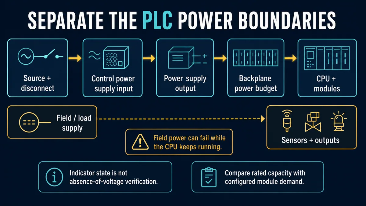
| Power boundary | Expected evidence | Typical divergent symptom |
|---|---|---|
| source/disconnect | correct authorized source and protective-device state | whole control supply absent or unstable |
| power-supply input | within installed product specification under relevant condition | supply off, cycling or undervoltage diagnostic |
| power-supply output/status | documented status and output behavior within load | input present but rack/CPU not powered or supply faults |
| backplane/system power | configured modules within capacity and distribution components present | boot loop, missing modules or overload event |
| CPU local state | completes startup and presents expected diagnostics | CPU remains off/inoperable despite valid upstream evidence |
| field/load supply | correct independent supply and channel/module status | CPU RUN but sensors/outputs/remote drop unavailable |
Recalculate the configured power budget
Use the vendor's current design tool or tables for the exact rack, supply, CPU and modules, including extension racks, redundancy and environmental derating. Compare configured and physically installed modules. A recent addition, higher-demand replacement, missing system-power module, loose distribution connector or derated supply can create a negative margin.
Calculate by each documented rail or segment only where the manufacturer defines it; do not add unlike values into one meaningless watt total. Include startup/inrush or redundancy behavior when the product requires it. A configuration tool result is a design check, not proof of physical integrity, and a power LED is not proof of adequate margin under load.
Correlate resets with source, load and environment
For intermittent restarts, align controller boot/diagnostic time with power-monitor events, supply status, backplane overload diagnostics, added/removed module events, cabinet temperature, ventilation/fan state and nearby load operation. A reset during motor starting may reflect source sag, shared supply loading, interference, application behavior or coincidence. Use qualified instruments and an approved measurement plan appropriate to the circuit and event; do not expose live parts to attach an ad hoc meter.
| Pattern | Supporting evidence | Next controlled comparison |
|---|---|---|
| all rack indicators extinguish together | source/supply event at matching time | upstream monitor and supply status under representative load |
| supply status faults but input remains valid | supply output/load/thermal condition | documented load budget and approved substitute/test |
| CPU restarts while neighboring supply indication remains | backplane/local CPU/firmware/storage or indication limitation | diagnostic boot sequence plus rack/module evidence |
| CPU RUN but field points all inactive | separate field/load supply or remote I/O issue | module/field-power diagnostics and I/O guide |
| fault appears as cabinet warms | thermal limit, ventilation, supply derating or component issue | temperature/event trend and installed thermal design |
| boot loop begins after module addition | power budget, configuration/compatibility or module fault | restore approved configuration and follow vendor isolation procedure |
Live mini-lab
Try it: press START, then STOP
A stop-dominant seal-in rung: START latches the motor output through its own contact, and STOP breaks the circuit.
Watch the output lamp: it stays on after START until you press STOP.
Free to start · runs in your browserOpens plcsimulationsoftware.com — same team
Diagnose CPU startup, STOP and fault states
Follow the boot sequence without interrupting valid activity
Determine the documented power-up sequence and normal duration. Siemens' S7-1500 system manual describes a flash test, system initialization and memory-card evaluation before the CPU reaches STOP on first power-up. Rockwell status messages include tests, backup-energy charging, SD-card save/load and firmware activity. Interrupting a legitimate firmware or nonvolatile-memory operation can create a more serious failure.
If the sequence repeats, record the last stable message/state and interval. Check power/backplane evidence, memory/storage access, project compatibility and firmware/update state. Do not repeatedly cycle power; every cycle can stress storage, erase volatile context and prevent a slow but valid operation from completing.
| Startup observation | Evidence branch | Key caution |
|---|---|---|
| never begins visible self-test | upstream power/backplane or CPU hardware/status indication | verify energy state safely; do not assume no hazardous voltage |
| self-test fails with exact code | internal diagnostic, firmware or hardware | preserve code and use vendor fault reference/support |
| stalls at storage/project load | card/image/compatibility/capacity or access state | do not remove media during access |
| completes to STOP | mode/startup condition/application fault | STOP can be expected; read reason before changing mode |
| reaches RUN then faults | task/application, I/O, communications, thermal or power event | capture first-out code and preceding event |
| repeatedly restarts | power budget/source, watchdog, firmware/storage or internal fault | reduce uncontrolled cycling and preserve interval evidence |
Distinguish recoverable, nonrecoverable and consequential faults
Use the controller's own classification. Rockwell Logix controllers distinguish major/minor and recoverable/nonrecoverable faults; exact code and controller family decide whether a handler, fault clear, application download or hardware action applies. A downstream I/O fault may leave the CPU running, while an internal nonrecoverable fault can stop task execution and outgoing connections.
Do not clear a recoverable fault until the cause and repeat behavior are understood. A task watchdog may be caused by application execution time, a loop, changed task loading or a diagnostic condition—not a defective CPU. The debugging guide owns task/logic investigation; this guide ensures the controller state is not misdiagnosed as a power or memory failure.
Understand PLC memory and storage domains
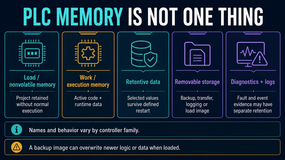
Map load, work, retentive and removable storage separately
PLC documentation uses different names and implementations, but several questions recur: where the application is stored when power is off; what code/data executes in work memory; which values are retentive across defined restart; whether a battery or energy-storage system supports retention; what removable media stores; and where diagnostic/log data persists.
Siemens S7-1500 uses the SIMATIC Memory Card as load memory for the CPU family. Rockwell ControlLogix 5590 includes a microSD card that can store a nonvolatile image and can be configured to load on power-up. Schneider M580 documentation separates memory-card access and backup status. Mitsubishi iQ-R supports internal/SD recording and event/history functions. None of these facts makes the cards interchangeable or their load behavior universal.
| Memory/storage question | Evidence to record | Risk if assumed |
|---|---|---|
| where is the executable project loaded from? | controller family, configured power-up behavior and image revision | older or incompatible project overwrites current logic |
| what is retained through power loss/restart? | retentive ranges/tags, restart class and energy/battery status | recipes, totals, states or safety-related data reset/retain unexpectedly |
| is removable media being accessed? | documented access LED/message and operation state | removal corrupts data/image or interrupts load/save |
| does media contain the intended image? | trusted export/hash/version and project/firmware compatibility | unknown card becomes production master |
| is memory capacity exhausted? | vendor capacity report by memory type and logs/files | download, logging, recipe or firmware operation fails |
| where do diagnostics persist? | buffer/log retention, rollover and export behavior | recovery erases first-out evidence |
| what protects power-down save? | battery/energy-storage type, status and product procedure | program/retentive data not saved as expected |
Do not generalize battery and energy-storage behavior
Some PLCs use batteries for selected memory or clocks, some use capacitors/energy-storage modules, and some use nonvolatile technologies without a replaceable battery for the application. A low-battery or backup-energy message has product-specific urgency and power-down consequences. Record it, save the approved project/data as directed, and follow the exact replacement procedure.
Rockwell's current 5590 status-message documentation distinguishes backup-energy low/hardware failure and directs project saving before power removal and controller replacement for those conditions. It also warns not to remove an SD card during save. Do not translate that procedure to a different controller.
Investigate lost program or changed retained data as a configuration event
If a PLC appears to lose its program after power cycle, determine whether it actually has no project, loaded a configured nonvolatile image, rejected an incompatible/corrupt image, performed a memory clear, booted different firmware, or started with initialized/nonretentive data. Compare power-up/load configuration, online project identity, card/image version, controller logs, audit/change history and retentive-data design.
“Program was lost” should not be concluded solely from outputs off or HMI disconnected. The CPU may be in STOP, have an I/O/communications fault, lack field power, or run an older application with different addressing.
Locate the first failed boundary
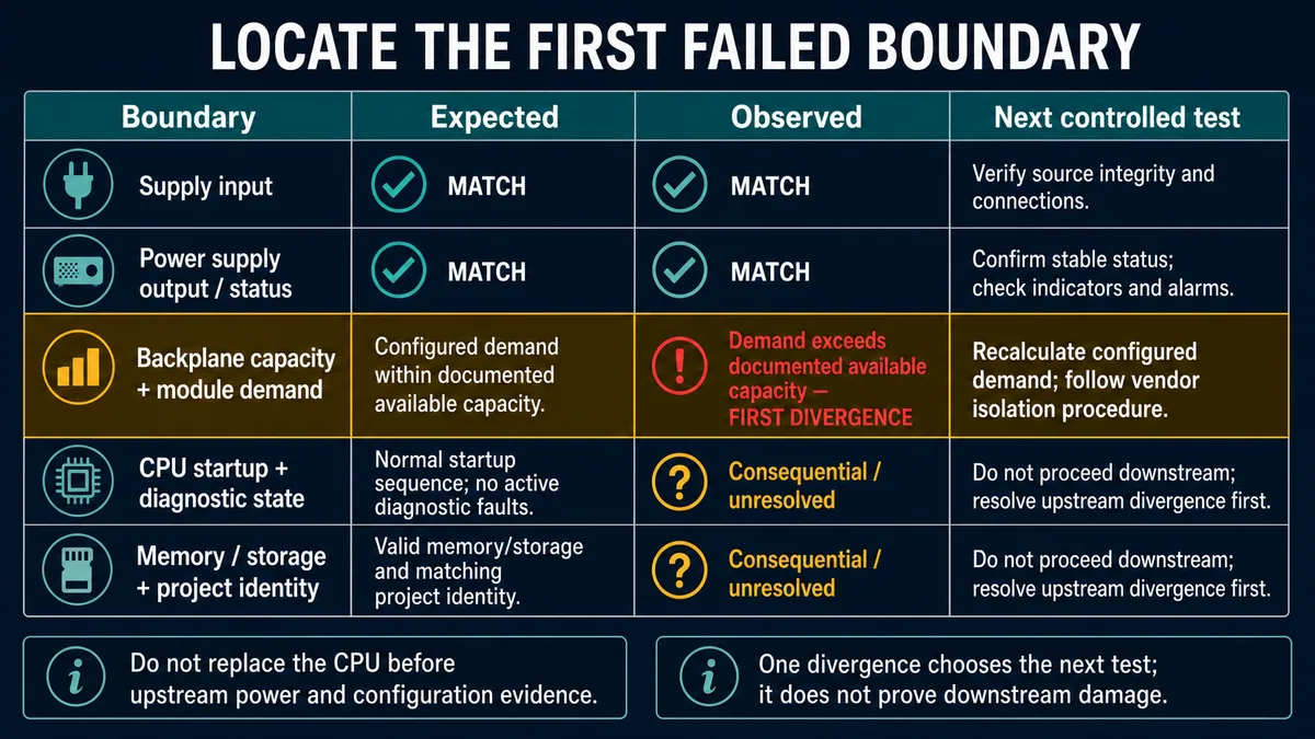
Stop downstream diagnosis after an upstream divergence
Test expected versus observed state in order: approved supply input, supply output/status, backplane capacity and installed demand, CPU startup/diagnostics, then memory/storage/project identity. If the configured demand exceeds documented capacity, resolve that design divergence before declaring the CPU or memory card defective. Downstream symptoms may be consequential.
| First divergence | What it supports | Controlled next action |
|---|---|---|
| supply input | source/protection/wiring or upstream power event | qualified source verification and drawing comparison |
| supply output/status | power supply/load/thermal condition | vendor diagnostic and approved known-good/load-isolation procedure |
| backplane capacity/configuration | overload, missing distribution component or installed/configured mismatch | recalculate demand and restore approved module configuration |
| CPU self-test/diagnostic | firmware/internal hardware/thermal or explicit CPU fault class | preserve exact code; follow vendor recovery/support path |
| memory/storage access | media, image, compatibility, capacity or access-state issue | preserve media/image identity and follow product procedure |
| project identity/retention | load-on-power-up, restore, clear, version or retention design issue | compare audit trail and validated backup before download |
Use substitution only when it isolates one boundary
A known-good power supply, CPU, card or rack component is useful only when compatibility is verified, process risk is controlled and one variable changes. Swapping a CPU can also change firmware, identity, communications, stored application and retentive data. Swapping storage can trigger a load. Document the original position, settings and serials and retain rollback.
The PLC repair guide owns bench-versus-field repair boundaries, replacement decisions and post-repair acceptance. Do not open or component-repair a PLC power supply or CPU based on this system-level guide.
Choose a controlled recovery action
Match the least destructive action to the fault class
A recoverable application fault may permit an authorized fault clear after the cause is corrected. A temporary external power event may require controlled restart and full state validation. A missing/invalid project may require restoration of a verified compatible image. A confirmed internal nonrecoverable or backup-energy hardware failure may require replacement. These are different decisions.
| Candidate action | Preconditions | Main data/process risk |
|---|---|---|
| clear recoverable fault | exact code classified, cause corrected, output/restart behavior approved | fault immediately repeats or machine resumes unexpectedly |
| controlled restart | evidence saved, power stable, startup/retention known, process prepared | volatile/diagnostic state lost; automatic sequence restarts |
| download validated project | identity/firmware/hardware compatibility and change approval | current online edits/data/configuration overwritten |
| load nonvolatile/removable image | image provenance/revision and configured load behavior verified | older logic, parameters and tag data replace current state |
| memory clear/factory reset | product-specific escalation, full restore package and authorization | application, network settings, firmware and evidence erased |
| firmware recovery/update | trusted correct package/tool, stable power and compatibility plan | interrupted update or incompatible application/hardware |
| hardware replacement | failed component boundary proven; spare compatibility and restore plan | new identity/firmware/storage and process commissioning required |
Never make reset the diagnostic test
Rockwell 5590 documentation distinguishes stage-one and stage-two reset behavior; one clears application/memory while retaining network settings, and the deeper reset returns out-of-box state including firmware. Other families use different controls and consequences. Publishing a universal press-and-hold sequence would be unsafe and inaccurate.
If support directs a reset, record why, exact controller procedure, expected losses, backup verification, network/firmware restoration, security trust/certificates, safety validation and acceptance matrix. Treat it as a controlled change, not a harmless reboot.
Commission CPU, memory and power recovery
Prove the complete restart and runtime state
After correction, do not stop at a green RUN indicator. Verify power budget and diagnostics, controller mode, project/firmware identity, memory/storage state, forces/edits, tasks, I/O ownership and quality, communications, retained values, clocks, alarms, HMI/historian, outputs and process permissives. Observe sufficient time and representative load to disprove the original fault signature.
| Acceptance case | Evidence | Pass question |
|---|---|---|
| cold start | full display/LED sequence, diagnostic buffer and time to intended mode | does startup complete without unexplained loop/fault? |
| warm/controlled restart if applicable | retention and task/application state | do specified values retain/reset exactly as designed? |
| normal configured load | power/backplane status and stable diagnostics | is power capacity valid under representative demand? |
| peak operating condition | source/supply/temperature and controller event trend | does the original intermittent reset stay absent? |
| project validation | online/offline identity, signatures/hashes and versions | is the approved application actually running? |
| memory/storage | access status, capacity, image/load configuration and logs | is no unexpected save/load/error active? |
| I/O and communications | module/device state, quality and fresh data | are all required producers/consumers healthy? |
| forces/edits | explicit inventory and authorized final state | are no unintended force or pending edit left? |
| machine/process recovery | permissives, alarms, sequence and operator acceptance | can operation resume without unexpected motion? |
Write the cause at the deepest proven boundary
“CPU bad” is rarely an adequate cause statement. A stronger record is: “After module addition, the configured S7-1500 power balance became negative; the CPU diagnostic buffer logged the overload and restarted until the added demand was removed and the approved supply architecture corrected.” Or: “ControlLogix backup-energy hardware warning preceded power loss; the project was saved to verified SD media and the confirmed controller hardware was replaced under the vendor procedure.”
Attach before/after versions, calculations, codes, configuration, recovery decision, replacements and acceptance results. Add prevention: design-tool power check, controlled spare image, storage/energy-health monitoring, environmental alarm, backup audit, startup checklist or diagnostic-buffer collection.
Troubleshooting sequence by symptom
Follow the shortest evidence path
| Symptom | First action | Second action | Likely owner |
|---|---|---|---|
| PLC completely dark | establish safety boundary; verify source/supply status by approved procedure | trace backplane/CPU power path and demand | source/supply/backplane |
| PLC repeatedly restarts | preserve boot sequence, buffer and interval | correlate power budget/source, storage and thermal events | power/CPU/storage |
| PLC in STOP after outage | read mode and exact reason/fault | verify project, startup and retained-state behavior | CPU/application/memory |
| RUN light on, machine dead | check I/O quality, field/load supplies and permissives | trace outputs/process path | I/O/application, not necessarily CPU |
| memory/card light active | identify documented save/load/access operation | wait/follow manual; do not remove media | storage/project |
| memory/card not recognized | preserve status and card/image identity | check compatibility/access/capacity with manual | storage |
| program appears missing after reboot | compare online state and power-up load/clear history | validate nonvolatile image and audit trail | project/memory/configuration |
| backup battery/energy warning | preserve exact message and project/data | follow model-specific save/replacement procedure | retention hardware |
| CPU faults under high cabinet temperature | record internal/cabinet temperature and preservation code | inspect thermal design, loading and environment | thermal/hardware/power |
| CPU fault follows module addition | recalculate power and compatibility/configuration | restore approved configuration and isolate per vendor | design/backplane/module |
Diagnostic answer map for PLC CPU, power and memory faults
| Question a technician or AI assistant may ask | Short, extractable answer | Evidence that decides it |
|---|---|---|
| Why will my PLC not power on? | Separate source, supply input, supply output/status, backplane capacity and CPU state before replacing the controller. | approved power-path evidence and module-demand calculation |
| Does an unlit PLC LED mean power is off? | No. An indicator is not qualified absence-of-voltage verification and may not cover every source or backfeed. | site isolation procedure and qualified test evidence |
| Why is the PLC in STOP mode? | STOP can be commanded, expected after startup, or caused by an application/configuration/diagnostic condition; read the exact reason. | mode switch/software mode, diagnostic buffer and startup events |
| Should I reset a faulted PLC? | Not until code, cause, forces/edits, project/memory state and restart consequences are preserved and authorized. | fault classification and recovery/rollback plan |
| Why does a PLC lose its program after power cycle? | It may clear, load an older image, reject storage, use incompatible firmware or only lose nonretentive data; prove which event occurred. | power-up load settings, image/project identity, logs and retention design |
| Can field I/O lose power while the CPU stays in RUN? | Yes. Controller/backplane and field/load supplies can be separate. | module channel/field-power diagnostics and drawings |
| Does a memory card contain the current PLC program? | Not necessarily. Verify image revision, configured load behavior, compatibility and provenance before loading it. | trusted card/image export and online project comparison |
| When should a PLC CPU be replaced? | After upstream power/configuration, firmware/storage and environmental boundaries are excluded or a documented internal nonrecoverable hardware fault confirms replacement. | exact diagnostics, controlled isolation and vendor guidance |
Frequently asked questions
What should I record before power-cycling a PLC?
Record the exact LED/display pattern and sequence, operating mode, controller/module fault codes and buffer, timestamps, forces, online edits, project/firmware identity, memory-card/storage and battery/energy status, power/backplane diagnostics, I/O/communication state and current process condition. Define restart consequences and rollback first.
Why are all PLC lights off?
The source or control supply may be absent, the supply may not produce valid output, the backplane distribution may be incomplete/overloaded, the CPU may not receive internal power, or the indicators/CPU may have failed. LEDs off do not prove de-energization. Trace the designed power boundaries under the approved electrical procedure.
What does a red PLC CPU light mean?
There is no universal meaning. Depending on family and pattern it can indicate startup tests, firmware activity, major fault, diagnostic event, inoperable state, configuration or other conditions. Record every LED/display state and use the exact catalog, firmware and product manual plus detailed diagnostics.
Can a PLC run with a power supply problem?
It can run while a separate field/load supply is missing, while a diagnostic or marginal condition exists, or until an intermittent source/load/thermal event causes reset. Conversely, a backplane power-budget fault can prevent stable startup. Prove supply and module state rather than infer from RUN alone.
How do I know if a PLC power supply is bad?
Confirm approved input evidence, documented supply output/status under the configured load, backplane demand, environment and connectors/distribution. Use an approved compatible substitute only if it changes one boundary. Do not condemn the supply from a CPU symptom or LED alone.
What is the difference between PLC load memory and work memory?
Load/nonvolatile memory retains a project or load image, while work/execution memory holds active code and runtime data used during execution. Retentive data and removable storage may be separate again. Names, movement between domains and power-loss behavior vary by controller family.
Can removing a PLC memory card damage the program?
Removing media while it is being accessed can corrupt or interrupt data and image operations. Some controllers also require the card for load memory or use it for configured power-up loading. Read the access indicator/message and exact manual; do not remove it as a generic troubleshooting step.
Why did retained PLC values change after a restart?
The tags may not be configured retentive for that restart class, the controller may have loaded values from a nonvolatile image, backup energy may have failed, memory may have been cleared, or startup logic may initialize them. Compare retention configuration, power-up/load events, energy status and startup logic.
When is a PLC factory reset appropriate?
Only as a product-specific, authorized recovery step with evidence preserved, the exact consequences known, a verified full restore package, trusted firmware/tools, network/security restoration and commissioning plan. It should not be used to discover whether a fault disappears.
How do I prove a PLC CPU or memory repair is complete?
Reproduce representative cold/warm startup, normal and peak load, project identity, memory/storage and retention behavior, diagnostics, I/O/communication quality, forces/edits, alarms and process recovery. The original fault signature must remain absent for a defined duration and transaction/operation count.
Sources, review scope, and limitations
This guide synthesizes vendor and regulator evidence for a reusable diagnostic method. It deliberately omits universal voltage values, test points, card-removal steps, reset button sequences and component-repair instructions because those vary by product and can erase evidence or create electrical/process hazards.
- OSHA 29 CFR 1910.333: Selection and Use of Work Practices — de-energization, lockout/tagging and qualified verification requirements.
- OSHA Interpretation: LED Device and Verification of De-energization — why an indicator is only a redundant status indication, not the required electrical verification.
- Siemens S7-1500 / ET 200MP System Manual, 11/2024 — commissioning sequence, system/load-current power, power balance and overload behavior.
- Siemens S7-1500 Diagnostics Function Manual, 11/2024 — system diagnostics, device/module details and diagnostic text/remedy surfaces.
- Siemens CPU 1515-2 PN Equipment Manual — product-specific RUN/STOP, ERROR and MAINT combinations, startup, force, memory-card and firmware states.
- Rockwell Automation ControlLogix 5590 Controller User Manual — controller operation, diagnostics, fault handling, nonvolatile memory, SD card and recovery context.
- Rockwell Automation ControlLogix 5590 General Status Messages — backup energy, startup tests, SD save, firmware and download status meanings.
- Rockwell Automation ControlLogix 5590 Controller Details — connectors, status displays, mode, storage and distinct reset consequences.
- Rockwell Automation ControlLogix 5580 Controller Status Indicators — RUN/FORCE/OK/SD states and limits of indicator-only diagnosis.
- Rockwell Automation ControlLogix 5590 Memory Card Specifications — nonvolatile image, manual save/load and configurable power-up load behavior.
- Schneider Electric Modicon M580 Hardware Reference Manual, Version 17 — current CPU, power-supply, rack, memory/storage and hardware diagnostic reference.
- Mitsubishi Electric MELSEC iQ-R CPU Module Manual Index — current CPU, power-supply/base and troubleshooting manuals by revision.
- Mitsubishi Electric MELSEC iQ-R CPU Features — event history, internal/SD logging and CPU diagnostic/monitoring capabilities.
- Rockwell Automation ControlLogix Chassis and Power Supply Documentation — current selection, specification and installation document routing for chassis and supplies.
Now run it · free to start
Learn a repeatable way to find the fault
Split a stopped machine into input, logic, output and physical response, and take the measurement that proves each stage. Practised on simulated machines. Free to start.
Ownership disclosure: PLC Programming IO and PLC Simulation Software are operated by the same publisher.
PLC Programming IO Editorial Team
Industrial automation education, references, and software testing
The PLC Programming IO Editorial Team publishes sourced industrial-automation education and documents how material is reviewed, tested, and corrected. A team byline means the publisher is responsible for the page; it does not represent a fictional person or imply an engineering licence.
Coverage:
- • PLC programming concepts and examples
- • Vendor software tutorials and comparisons
- • SCADA, HMI, protocols, and instrumentation
- • Training, careers, and reference material
Review standard:
- • Prefer primary and official sources
- • Record software versions when material
- • Separate tested facts from estimates
- • Publish material corrections
Important scope note
This site provides education, not project-specific engineering approval. Safety, code, and compliance decisions require a qualified person with access to the actual machine and jurisdiction.