PLC Repair: Diagnose, Recover, Repair or Replace Safely
Prove a PLC hardware fault, preserve the program and configuration, choose repair versus exchange or migration, and acceptance-test the returned controller.
Review status: Editorially reviewed against cited regulator, NIST and automation-manufacturer service guidance; installed-product instructions, regional service terms and site safety procedures remain authoritative
Direct answer
Before sending a PLC for repair, prove that the suspected module—not its power, backplane, field wiring, network, firmware, program, grounding or environment—is the failed boundary. Capture indicators and diagnostics, record the full catalogue/part number and hardware series, preserve a verified upload plus firmware and network configuration, and reproduce the failure with an approved known-good rack, simulator or substitution test. Then choose among factory/qualified repair, tested exchange, compatible replacement or controlled migration based on downtime, lifecycle, safety/security requirements, recoverable configuration, warranty, functional-test coverage and recurrence risk.
Do not open or component-repair a production PLC merely because an indicator is dark or a communication port is silent. Board-level repair requires ESD control, product knowledge, controlled power, proprietary fixtures, suitable rework capability and a functional test that exercises the repaired unit—not only a visual inspection or power-on check. Safety PLCs, conformal-coated units, hazardous-location equipment and products under warranty may have additional restrictions. Use the manufacturer or a provider whose exact scope, traceability and test evidence meet the site's requirements.
Treat recovery as a system task. A returned CPU is not ready for service until its identity, hardware revision, firmware, memory, clock, communications, redundancy/safety role where applicable, I/O behavior, program/configuration restoration and fault history have been tested in an isolated environment. Finally, correct the environmental or electrical cause that damaged the first unit, or the repair may fail again.

Define repair, recovery, exchange and migration
“PLC repair” is used for several different jobs. An onsite technician may repair field wiring or reload a configuration without touching electronics. A repair centre may replace components and functionally test the module. An exchange program supplies a tested unit and takes the failed one as a core. A lifecycle project moves the application to a newer controller family.
Service-path definitions
| Path | What changes | Best fit | Main risk to control |
|---|---|---|---|
| configuration recovery | firmware, program, parameters, memory card or network settings | hardware is healthy but application state is lost/corrupt | restoring an unverified or incompatible backup |
| field-system repair | power, wiring, connector, backplane, network or environment | module was blamed but external boundary failed | energized work or moving the fault to replacement hardware |
| module repair/remanufacture | internal components plus cleaning, updates and functional test per provider scope | repairable unit, tolerable turnaround, trusted provider | incomplete test coverage, undocumented parts/firmware changes |
| standard exchange | failed core returned for a tested equivalent | downtime matters more than retaining the same serial unit | wrong series/revision, no immediate configuration compatibility |
| advance/priority exchange | replacement ships before failed core is processed | critical downtime with qualifying product/contract | core-return terms and uncontrolled emergency installation |
| compatible replacement | new or remanufactured spare of approved catalogue/series | known configuration and hardware compatibility | counterfeit/gray-market provenance or revision mismatch |
| migration | application engineered onto a supported platform | obsolescence, security/support or capacity risk exceeds repair value | hidden behavior differences, I/O/network conversion and validation effort |
Manufacturer services demonstrate these distinctions. Rockwell Automation describes repair, remanufacture and priority exchange with functional testing and lifecycle checks. Schneider Electric offers regional repair, exchange and refurbishment services, while its PLC modernization service addresses systems better moved to current platforms. Exact eligibility, warranty and turnaround vary by region and date, so verify a current written quotation.
Establish the safety and authority boundary
A PLC can energize contactors, drives, valves, heaters, robots and stored mechanical or fluid energy. Removing a module can also disable protective sequencing or make outputs assume a configured fault state. Before service, identify every affected energy source and every controller interaction.
Control off is not energy isolated
OSHA's hazardous-energy guidance states that control-circuit devices such as push buttons and selector switches are not energy-isolating devices. The same reasoning applies to an HMI stop, PLC program-mode switch or forced output-off state. Follow the site's documented shutdown, isolation, lockout/tagout, stored-energy control and verification procedure.
| Activity | Minimum boundary | Do not substitute |
|---|---|---|
| inspect LEDs or online diagnostics | authorized operating-state observation with arc/electrical boundaries respected | open-door access without required qualification/PPE |
| remove a PLC/module | documented equipment isolation and verification | program mode, E-stop or output inhibit alone |
| resistance/continuity test | de-energized isolated circuit and protected electronics | measuring resistance on an energized/connected circuit |
| bench power-up | current-limited approved fixture, known pinout and contained test setup | improvised wiring from an unknown supply |
| temporary re-energized test | formal testing/positioning sequence and cleared personnel/tools | leaving covers, wiring or energy controls in an ad hoc state |
| safety-controller work | safety lifecycle, authorized change and validation procedure | ordinary PLC swap checklist alone |
OSHA provides a specific sequence when lockout/tagout devices must be temporarily removed for testing or positioning: clear tools/materials, remove employees, remove controls as authorized, energize/test, then de-energize and reapply energy control before continuing service. Site rules and local law may be stricter.
Preserve evidence before removing hardware
A power cycle, battery removal, reset or module swap can erase volatile diagnostics and break the causal chain. Capture what the controller and neighboring devices report before the state changes, when safe and authorized.
Failure evidence packet
| Evidence | Record | Why it matters |
|---|---|---|
| full identity | manufacturer, catalogue/part number, series/revision, serial, manufacture/date code | defines compatibility, firmware and service eligibility |
| lifecycle status | active/mature/discontinued, repair and replacement status | informs repair versus migration decision |
| visible state | every LED/display state, sequence and photo with timestamp | boot and hardware fault patterns can be transient |
| controller diagnostics | major/minor fault, event log, module status, watchdog, temperature/power status | separates CPU, rack and application failures |
| application context | last known program revision, mode, recent download/change, process event | identifies configuration versus hardware change |
| electrical/environment | rack supply, grounding, surge/UPS event, cabinet heat, fan/filter, moisture, contamination | exposes external causes and recurrence risk |
| comparison evidence | other modules/racks affected, known-good substitution result, bench reproduction | establishes whether failure follows the module |
| chain of custody | remover, time, location, ESD packaging seal and destination | protects traceability and repair analysis |
Avoid cleaning corrosion, reseating every connection or discarding the power supply before photographing the as-found state. Correct urgent hazards, but document what changed and when.
Prove the failed boundary
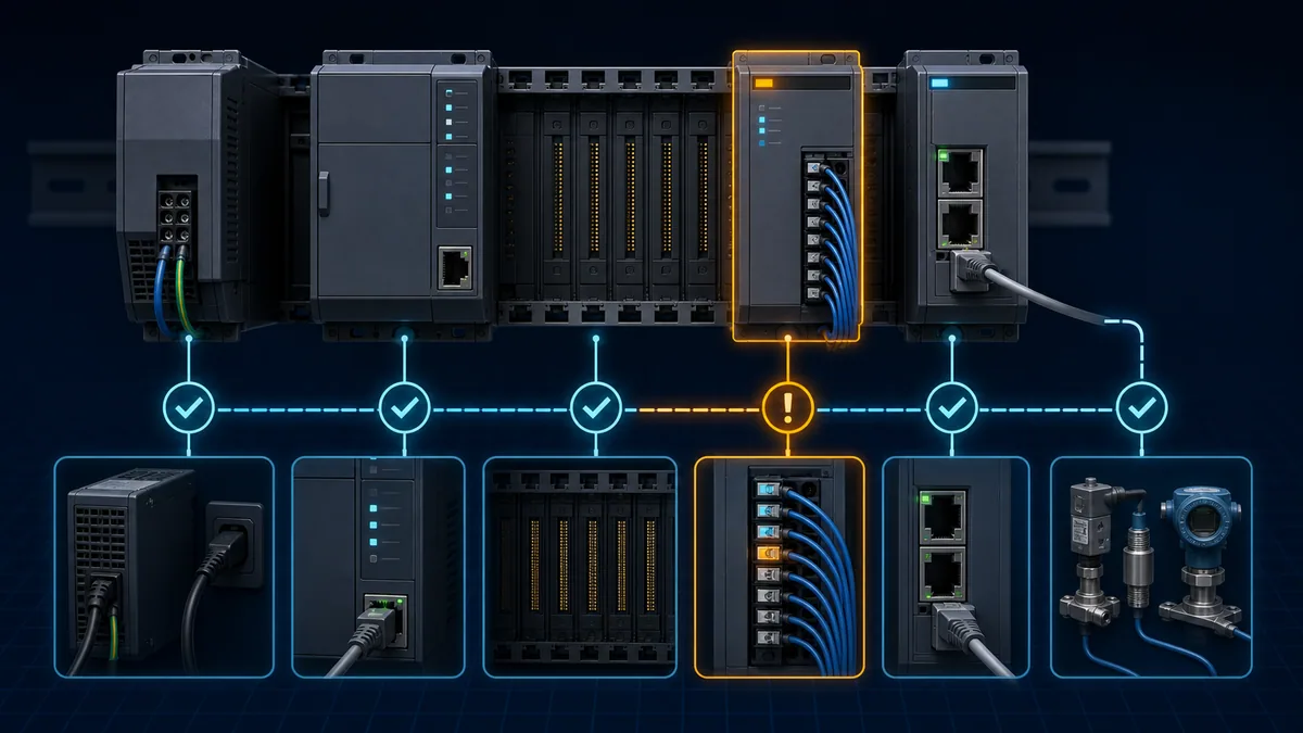
A PLC rack is a system: incoming supply, PLC power supply, backplane, CPU, memory, communication adapters, I/O modules, terminals, field devices and application code. A dark CPU can be caused by missing rack power. A faulted I/O module can be caused by a shorted field circuit. A silent Ethernet port can be caused by duplicate addressing or a switch port.
Rack isolation map
| Symptom | External or system causes to exclude | Module-focused confirmation |
|---|---|---|
| entire rack dark | incoming/control supply, fuse/protection, disconnect, wiring, rack power supply | approved bench supply/rack test if product supports it |
| CPU will not boot | supply dip, backplane, memory card, incompatible firmware/project, key/mode state | minimal supported rack and manufacturer boot diagnostics |
| CPU repeatedly resets | marginal supply, backplane load, grounding/EMI, watchdog/application, heat | event/fault log plus controlled minimal configuration |
| one input stuck | field voltage, common/reference, terminal, sensor, channel mapping, force | isolated simulator at module terminal and channel status |
| one output fails | load short/overcurrent, external supply/common, wiring, protection, force/inhibit | protected test load and per-channel diagnostic |
| communication port silent | cable, switch, addressing, protocol mode, security/configuration | loop/known-good network using product diagnostic tool |
| module works cold then fails | cabinet heat, connection expansion, moisture/contamination, marginal supply | temperature-correlated controlled reproduction by qualified provider |
| replacements fail in same slot | backplane/terminal/field fault or environment | stop substitutions; investigate rack/field boundary |
Use the PLC input and output troubleshooting guide for channel-level current/voltage evidence. Use intermittent PLC fault troubleshooting for vibration, condensation, contamination, heat and time-correlated capture.
Use substitution tests without damaging the spare
A known-good swap is useful only after verifying catalogue, series, firmware and electrical compatibility and excluding the fault that may have damaged the original. Placing a spare output module onto a shorted field circuit can destroy both units. Moving a CPU without a verified backup can create a second configuration problem.
Predictive swap plan
| Before swap | Required decision | Pass prediction | Stop condition |
|---|---|---|---|
| identity | exact or approved compatible hardware/series | rack recognizes module without unintended conversion | uncertain compatibility or safety listing |
| root-cause screen | field short, supply, backplane and environment checked | substitute is not exposed to known damaging condition | repeated failure or abnormal supply/temperature |
| recoverability | verified application/parameter/firmware media exists | original state can be restored or rolled back | only copy exists in suspect controller |
| change control | owner, outage, rollback and affected equipment documented | result is attributable and reversible | simultaneous unrelated changes |
| acceptance | test cases and expected raw I/O/comms states defined | module behavior can be proven beyond “no red LED” | no safe isolated test available |
Never hot-swap unless the exact product, slot, system design and manufacturer procedure explicitly permit it, and the activity is authorized. “The rack supports removal and insertion under power” is not a universal statement about every module, load or hazardous environment.
Preserve program, firmware and configuration
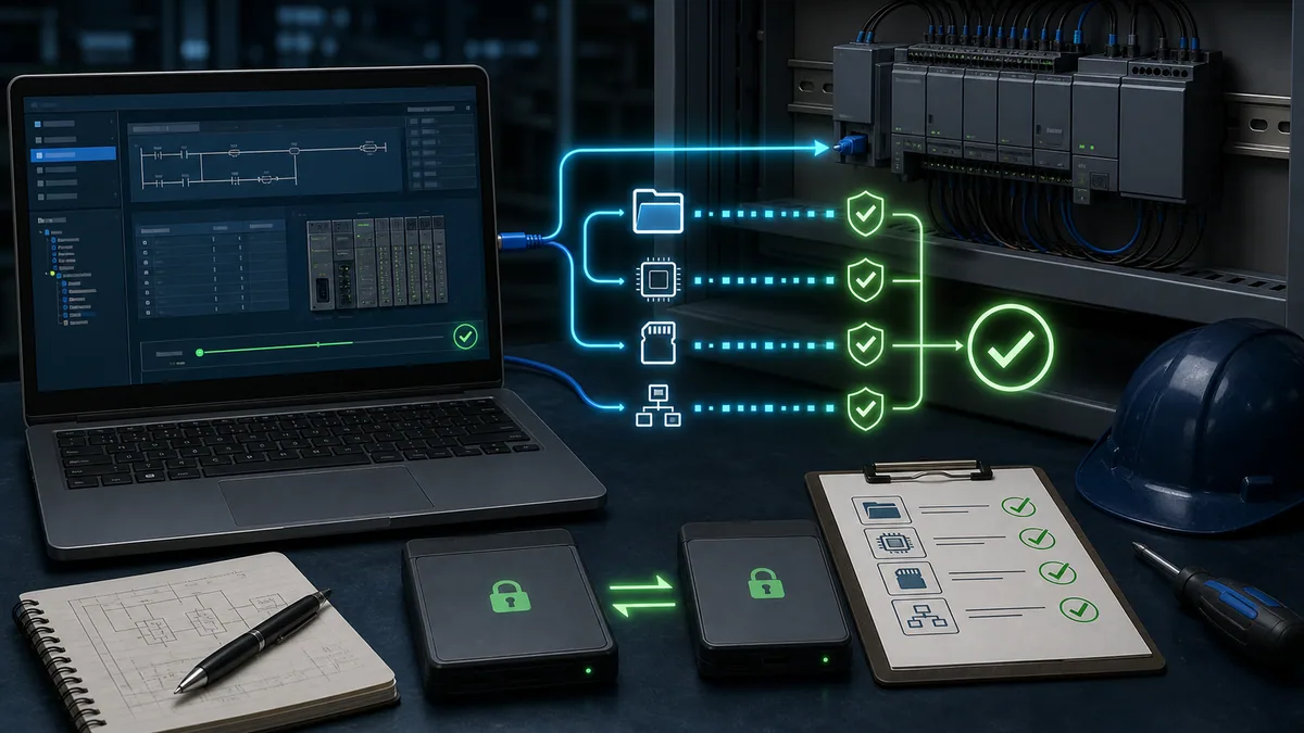
The hardware can be repaired while the machine remains unrecoverable because the last program, firmware or communication configuration is missing. A PLC recovery package should be created before failure and verified regularly.
Recoverability package
| Recovery item | Preserve | Verification |
|---|---|---|
| PLC project | native editable project plus vendor archive/export | opens in recorded software version; source matches running identity where determinable |
| controller image | supported nonvolatile/memory-card image or backup | restore test on approved spare/bench if feasible |
| firmware | exact version, release notes, approved installation package and entitlement | compatible with hardware series and engineering software |
| I/O configuration | module catalogue/series, slot, electronic keying and channel parameters | compare to physical rack and drawings |
| networks | addresses, names, unit IDs, routes, certificates/keys by secure procedure | offline inventory plus isolated communication test |
| HMI/drive/remote devices | linked projects and parameter sets | end-to-end tag/handshake test, not PLC alone |
| safety application | signatures, validation records and authorized source | handled under the safety lifecycle; do not treat as ordinary upload |
| credentials/licensing | securely controlled access, entitlements and recovery contacts | authorized recovery drill without exposing secrets |
NIST SP 800-82 recommends comprehensive backup and restore policy for industrial control systems, including current configuration and layered backups. NIST SP 1339 focuses specifically on operational-technology backup strategy. Apply those controls to more than the CPU project: engineering software, communications, recipes, safety records, certificates and dependent device parameters can all be restoration prerequisites.
Live mini-lab
Try it: press START, then STOP
A stop-dominant seal-in rung: START latches the motor output through its own contact, and STOP breaks the circuit.
Watch the output lamp: it stays on after START until you press STOP.
Free to start · runs in your browserOpens plcsimulationsoftware.com — same team
Classify common PLC failure modes
Failure mode changes both the proof needed and the service provider's test scope. “Dead PLC” is too vague for a useful repair request.
Symptom-to-repair evidence matrix
| Failure family | As-found evidence | Provider test request | Recurrence check |
|---|---|---|---|
| no power/boot | supply at rack, indicator sequence, power event | startup/current profile, internal rails, boot and thermal run | upstream surge, supply, grounding and heat |
| CPU fault/watchdog | raw fault codes, program/firmware, trigger sequence | memory, processor, firmware and runtime functional test | application loop, EMI, temperature, power quality |
| memory loss/corruption | battery status, checksum/signature, last known project | memory retention and supported firmware/configuration test | battery maintenance, unauthorized change, cyber incident |
| communication failure | link state, counters, capture, port/configuration comparison | every claimed port/protocol at relevant speed/mode | cable/switch/grounding, address conflict, network surge |
| I/O channel failure | terminal measurements, field circuit isolated, channel diagnostics | each channel across range/load and isolation boundary | short/overvoltage, inductive suppression, common wiring |
| intermittent thermal | temperature/time correlation and cabinet evidence | controlled thermal soak/cycle under functional load | filters/fans, spacing, contamination, ambient rating |
| contamination/corrosion | photographs, contaminant/process context, affected area | cleaning feasibility, coating damage and leakage/insulation test | enclosure/gland, condensation, chemical exposure |
| mechanical connector/backplane | vibration correlation, slot/substitution evidence | connector, solder/interconnect and vibration-sensitive test | rack support, terminal strain, vibration source |
If cybersecurity compromise is plausible—unexpected firmware/project, unknown account changes, network indicators or several controllers behaving abnormally—do not frame the event as ordinary hardware repair alone. Preserve evidence, isolate according to the incident plan and use the organization's OT incident-response process. A repaired board does not establish that the restored program is trustworthy.
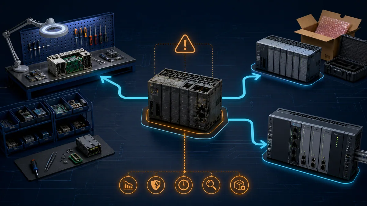
Choose repair, exchange, replacement or migration
The cheapest unit price is not necessarily the lowest production risk. Compare recovery time, probability of successful repair, supported lifecycle, validated spare availability, configuration compatibility, provider evidence, warranty, safety/security implications and future exposure.
Decision matrix
| Condition | Repair | Exchange/replacement | Migration |
|---|---|---|---|
| supported product, noncritical spare available | good candidate if functional scope is clear | often fastest if exact compatible stock exists | usually unnecessary unless other drivers exist |
| discontinued but manufacturer still repairs | extends life while migration is planned | valuable strategic spare if provenance is strong | plan before repair/service window closes |
| no verified program/configuration | hardware repair alone may not restore service | same configuration blocker | reverse engineering may be major project risk |
| safety/security certification sensitive | manufacturer-approved path may be required | exact approved revision and validation needed | formal safety/security lifecycle project |
| repeated same failure | stop routine repairs until external/root cause is corrected | spare may fail identically | migration helps only if system cause is redesigned |
| downtime cost dominates | repair turnaround may be too slow | advance exchange or stocked tested spare | planned redundant/cutover architecture may reduce future risk |
| support/software ecosystem unavailable | repaired unit remains hard to maintain | replacement may still inherit ecosystem gap | migration becomes stronger despite engineering cost |
Create a total-risk comparison with numbers specific to the plant. Include downtime per hour, probability-weighted turnaround, engineering/validation labor, license/adapter needs, lost configuration risk, warranty, future failures and remaining lifecycle. Avoid publishing a universal “repair below 50% of new cost” rule; criticality and recovery confidence can outweigh price ratio.
Select a qualified repair provider
Provider claims should be converted into written scope and acceptance evidence. Manufacturer service pages emphasize factory-trained staff, sourced/genuine components, functional fixtures, updates, traceability and full-unit warranties. Ask exactly which of those apply to the submitted part number and failure.
Provider qualification checklist
| Question | Strong evidence | Warning sign |
|---|---|---|
| Is the exact catalogue/series supported? | written capability and service route for the unit | “all PLCs repaired” without model confirmation |
| How is incoming failure reproduced? | documented diagnostic and no-fault-found process | parts replaced without reproducing symptom |
| What components and changes are used? | traceable parts, controlled substitutes and change record | unknown-source components or erased markings |
| What functional testing is performed? | port, channel, load, memory, temperature/run and product-specific fixtures as applicable | powers on LED check only |
| Are firmware and security changes controlled? | authorized versions, release record and customer approval | unrequested firmware or unverifiable image |
| How are safety products handled? | explicit certification/scope and validation boundary | ordinary repair process applied to safety unit |
| What warranty and failure report are supplied? | written regional terms, serial tracking and repair/test report | vague promise with no unit traceability |
| How is customer configuration/data protected? | documented data handling, wipe/return policy and secure access | uncontrolled copying or retained credentials |
| What happens if no fault is found? | defined test duration, conditions, fee and returned evidence | “passed” without conditions or report |
| How are unrepairable/counterfeit units handled? | quarantine, notification, return/disposal authorization | substitution without customer approval |
Rockwell states that its facilities use functional testing and offers full-unit warranty terms, while warning about provenance, firmware, safety, cybersecurity and reliability risks in unauthorized supply paths. Mitsubishi Electric describes factory-trained technicians, manufacturer-sourced components and product testing. Schneider's current regional offers distinguish certified repair, exchange and refurbishment. These are useful benchmarks, not proof that every regional service covers every legacy unit.
Understand professional board-level repair
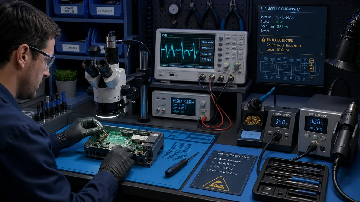
The safe and defensible educational boundary is what a professional process must prove—not step-by-step live board probing or component substitution. PLC electronics can contain hazardous input circuits, isolation barriers, multilayer boards, proprietary programmed parts and conformal coating.
Functional repair workflow
| Stage | Expected control | Deliverable |
|---|---|---|
| receiving | identity, condition, seal, configuration/data instructions and chain of custody | intake record and photographs |
| incoming test | reproduce customer symptom with safe product-specific fixture | failure mode or defined no-fault-found result |
| inspection | ESD control, magnification, contamination/thermal/mechanical evidence | findings linked to repair decision |
| repair/rework | qualified process, controlled parts, isolation/coating integrity and change trace | replaced/reworked items and applicable engineering updates |
| firmware/configuration | authorized image and customer-approved data handling | version/change record |
| functional test | every claimed interface/channel under representative load/conditions | measured pass report and duration |
| final quality | serial identity, cleaning/coating, enclosure, labels and tamper controls | release record, warranty and limitations |
| packaging | correct ESD and physical protection with moisture controls if needed | traceable shipment ready for acceptance |
A bench that can find a failed capacitor but cannot exercise the CPU, backplane, ports or I/O under representative conditions has not proven the PLC is fit for service. Conversely, providers may reasonably withhold proprietary fixture details; they should still define the functional outcome tested.
Package and ship the failed unit
Follow the provider's return-material authorization and manufacturer handling instructions. Preserve the as-found state unless safety or contamination policy requires special treatment. Remove batteries, memory cards, terminal blocks, connectors or accessories only as the written return instruction specifies—these items can contain needed configuration or failure evidence.
Return package contents
| Item | Include | Avoid |
|---|---|---|
| unit identification | catalogue, series, serial, site asset and RMA | adhesive over ventilation/connector surfaces |
| symptom statement | exact indicators/codes, timing, environment and reproduction steps | “dead” with no context |
| configuration direction | retain/wipe/return requirements, sensitivity and authorized contact | passwords printed loose in box |
| accessories | only items provider requests, individually identified | shipping unnecessary field terminal with live process wiring attached |
| ESD protection | suitable static-shielding packaging and grounded handling | ordinary plastic/bubble wrap touching electronics |
| physical protection | connector caps/support, cushioning and rigid outer container | loose module movement or foam that contaminates contacts |
| contamination disclosure | moisture, oil, corrosive, biological or hazardous exposure | sending hazardous contamination without notification |
| chain of custody | remover/packer, seal, courier, tracking and receipt | untracked handoff for critical asset |
Photograph the unit and packaging, record seals and retain shipment evidence. A damaged connector on arrival can otherwise be mistaken for the original failure.
Acceptance-test the returned or exchange PLC
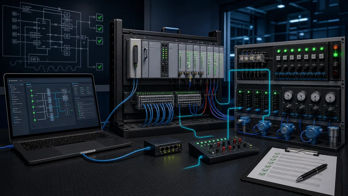
Do not install a returned controller directly into an uncontrolled production start. Build an isolated acceptance plan from the original symptom and the provider's claimed repair. Use a compatible rack, protected power, simulated I/O loads and segmented test network where feasible.
Bench and system acceptance matrix
| Gate | Test | Pass evidence |
|---|---|---|
| identity | inspect catalogue, series, serial, repair seal/report and physical condition | received unit matches approved order and compatibility decision |
| power/boot | controlled start, indicator sequence, diagnostics and warm run | stable boot with no unexpected faults/resets |
| firmware/memory | verify approved versions and retention through supported cycles | correct firmware and retained/recoverable state |
| engineering access | connect with recorded software/tool and upload/compare | expected identity and controlled project access |
| communications | exercise every required physical port/protocol and redundancy role | stable connections, counters and data exchange |
| digital I/O | simulate OFF/ON per channel with protected loads | all channels and diagnostics behave as specified |
| analog/specialty I/O | apply traceable points across required range/function | readings/output within product/site acceptance limits |
| fault response | inject safe approved faults and power/network interruptions | correct diagnostics, fail state and recovery behavior |
| original symptom | reproduce original trigger/temperature/duration as feasible | symptom absent under defined equivalent conditions |
| configuration restoration | load/verify project, addresses, parameters and dependent handshakes | documented comparison and version control |
| plant cutover | controlled installation and functional test with rollback ready | process, interlocks, alarms and recovery verified |
| soak/monitoring | defined operating window with logs/trends | no recurrence or new diagnostic drift |
Use the PLC troubleshooting simulator to rehearse fault isolation and acceptance cases before touching plant equipment. A browser lab can test diagnostic reasoning and program behavior; it cannot certify repaired electronics, isolation, environmental ratings or safety functions.
Prevent repeat PLC failures
The returned report should feed a corrective-action review. If the provider found an input-stage overvoltage, corroded connector or heat-damaged supply, compare that finding with the installation. Replacing the module without removing surge, condensation or enclosure heat preserves the failure mechanism.
Recurrence-control table
| Repair finding | Site investigation | Durable control |
|---|---|---|
| supply/input damage | transients, grounding/bonding, wrong voltage, failing supply/UPS | engineered protection and verified distribution, not repeated board repair |
| output driver damage | load current/inrush, coil suppression, short, shared commons | correct interface/protection and field-circuit correction |
| corrosion/contamination | enclosure ingress, washdown, chemical, condensation/dew point | enclosure/gland/environmental control and inspection |
| thermal damage | cabinet ambient, spacing, fan/filter, blocked airflow, load | thermal survey, maintenance and rated redesign |
| connector/solder fatigue | vibration, strain, unsupported cable, repeated handling | mechanical support, terminal practice and vibration control |
| repeated memory loss | battery policy, power-off duration, firmware, storage | monitored maintenance plus verified restore media |
| no fault found | intermittent trigger absent from bench | improve triggered logs, environmental evidence and reproduction conditions |
| obsolete part unrepairable | lifecycle/installed-base gap | migration roadmap, spares and recovery drill |
Build a repairable PLC spare strategy
Critical spares should be stored as recoverable systems, not anonymous modules. Track lifecycle status, firmware compatibility, configuration, battery/storage needs, periodic functional test, ESD/environmental conditions, licenses/cables and the time needed to install and validate them.
Critical-spare record
| Field | Example decision | Audit question |
|---|---|---|
| asset compatibility | approved racks, series and firmware range | can this exact spare replace each named installed unit? |
| configuration | controlled project/image and restore steps | was restore tested after the last change? |
| storage | ESD, temperature/humidity, battery interval and seal | does current condition meet manufacturer guidance? |
| functional exercise | power/boot, port and I/O test interval | did the spare pass, and is evidence retained? |
| logistics | location, access, courier/provider and RMA terms | can an authorized person obtain it during the outage? |
| lifecycle | active/discontinued/repair end date and successor | is migration funded before serviceability ends? |
| security | approved firmware, provenance and custody | can authenticity and trustworthy state be established? |
Manufacturer lifecycle tools and service networks are useful inputs, but the plant owns the installed-base mapping and recovery drill. A spare that has never been powered, has an expired battery, requires unavailable programming software or lacks a compatible series is inventory, not assured resilience.
Diagnostic answer map for search and AI-assisted troubleshooting
| User or AI query | Concise answer | Required qualification |
|---|---|---|
| Can a PLC be repaired? | Many PLC CPUs, power supplies, I/O and communication modules can be professionally repaired or remanufactured. | Eligibility depends on exact part/series, damage, lifecycle, safety/security scope and regional service. |
| How do I know the PLC itself is faulty? | Prove power, backplane, wiring, network, firmware and program first; then reproduce failure in an approved known-good boundary. | Protect substitutes from the suspected damaging cause. |
| Should I repair or replace a PLC? | Compare downtime, repair test/warranty, lifecycle, compatibility, recoverable configuration, recurrence and migration cost. | No universal price percentage fits every criticality. |
| What must be backed up before replacing a PLC? | Project, firmware, memory image, I/O/network configuration, dependent devices, licenses/credentials and safety validation records. | Verify the backup can be opened/restored using controlled tools. |
| Is a power-on test enough after PLC repair? | No; the repaired interfaces, memory, communications, I/O and original failure condition need functional testing. | Test scope depends on product and repair. |
| Can I replace components on a PLC board myself? | Production board repair requires qualified ESD/rework skills, product knowledge and functional fixtures. | Warranty, safety certification and proprietary parts/firmware may prohibit or invalidate DIY repair. |
| Can I hot-swap a PLC module? | Only when the exact product, slot, system and manufacturer procedure explicitly support it. | Authorization and electrical/process hazards still apply. |
| Why does the replacement PLC fail too? | An external supply, field-load, backplane, grounding, heat, contamination or configuration fault may remain. | Stop repeated substitutions and diagnose the system cause. |
| What should a PLC repair report contain? | Identity, incoming symptom/test, findings, changes/parts, firmware, functional test results, limitations and warranty. | Agree the deliverable before shipment. |
| How should a repaired PLC be returned to service? | Bench-test, restore/compare configuration, inject safe faults, controlled cutover, prove interlocks and monitor a defined soak period. | Safety systems require their formal validation lifecycle. |
Frequently asked questions
What is included in professional PLC repair?
A credible scope includes identity and incoming inspection, symptom reproduction, controlled component/rework or engineering changes, firmware/configuration handling, product-specific functional testing, final quality inspection, traceable packaging and written warranty/limitations. Exact scope varies by provider and module.
How can I prove a PLC CPU is faulty before sending it away?
Capture raw faults and LEDs, verify rack power and environment, preserve the project/firmware, test backplane and neighboring modules, and reproduce the symptom in a minimal approved rack or known-good boundary. Document every substitution and predicted result.
Is it better to use an OEM repair centre or an independent provider?
Choose by evidence: exact product capability, authorized parts/firmware, functional fixtures, safety/security scope, traceability, report, warranty, turnaround and regional support. OEM service can offer proprietary fixtures and engineering updates; a qualified independent may cover obsolete multi-brand assets. Verify the written scope.
Can a repaired PLC lose its program?
Yes, depending on CPU, memory technology, battery, repair action and provider data policy. Never rely on the submitted unit as the only copy. Preserve and verify the project, firmware, memory image and dependent configurations before shipment.
What information should I send with a PLC repair request?
Send complete identity, raw indicator/fault evidence, exact symptom and timing, environmental/electrical context, reproduction steps, prior substitutions, configuration-handling instructions, requested test scope and an authorized technical contact. Avoid vague descriptions such as “not working.”
How should a PLC module be packaged for repair?
Use the provider's RMA instructions, static-shielding protection, connector/mechanical protection, suitable cushioning, contamination disclosure and traceable shipment. Include memory cards, batteries or terminal blocks only when the written instruction requests them.
What does no fault found mean after PLC repair testing?
It means the provider did not reproduce the submitted symptom under its documented conditions; it does not prove the field system is healthy. Compare temperature, vibration, power, load, network and duration with the actual event and improve triggered evidence before resubmission.
Can a safety PLC be repaired like a standard PLC?
Do not assume so. Safety products can have manufacturer-only repair restrictions, certification, firmware, signature and validation requirements. Use the product safety manual, qualified provider and the site's functional-safety lifecycle.
How long should a repaired PLC be soak-tested?
There is no universal duration. Define a window that covers the original failure trigger, thermal stabilization, required ports/I/O, power cycles and representative load. Record the actual conditions; “ran overnight” without scope is weak evidence.
When should a PLC repair trigger a migration project?
Start migration planning when repair eligibility or spares are shrinking, software/support is unavailable, cybersecurity or safety requirements cannot be sustained, recovery drills fail, or repeated downtime exceeds the risk-adjusted migration cost. Repair can bridge the gap but should not hide an end-of-life exposure.
Sources, review scope, and limitations
This guide was reviewed on August 28, 2026 against public regulator, standards-agency and manufacturer material. Service capability, turnaround, warranty, supported catalogue numbers and regional terms change; obtain a current written quotation and use the exact installed product documentation.
- Industrial Repair Services — Rockwell Automation
- Spares and repair support — Siemens
- Repair solutions for factory-automation products — Mitsubishi Electric
- Global factory-automation service network — Mitsubishi Electric
- Repair and remanufacturing support — Schneider Electric
- Repair, exchange and refurbished service offers — Schneider Electric
- PLC modernization and replacement services — Schneider Electric
- NIST SP 800-82 Rev. 2, Guide to Industrial Control Systems Security
- NIST SP 1339, OT Backup Quick Start Guide
- 29 CFR 1910.147, control of hazardous energy — OSHA
- Testing or positioning machines during lockout/tagout — OSHA
The images are conceptual and do not define terminal pinouts, safe approach boundaries, ESD procedures, repair fixtures or wiring. This page does not authorize energized diagnostics, board-level repair, firmware modification, safety-system alteration or use of non-genuine components. Only qualified, authorized personnel following the site, manufacturer, provider and legal requirements should remove, repair, test or restore industrial-control hardware.
Now run it · free to start
Learn a repeatable way to find the fault
Split a stopped machine into input, logic, output and physical response, and take the measurement that proves each stage. Practised on simulated machines. Free to start.
Ownership disclosure: PLC Programming IO and PLC Simulation Software are operated by the same publisher.
PLC Programming IO Editorial Team
Industrial automation education, references, and software testing
The PLC Programming IO Editorial Team publishes sourced industrial-automation education and documents how material is reviewed, tested, and corrected. A team byline means the publisher is responsible for the page; it does not represent a fictional person or imply an engineering licence.
Coverage:
- • PLC programming concepts and examples
- • Vendor software tutorials and comparisons
- • SCADA, HMI, protocols, and instrumentation
- • Training, careers, and reference material
Review standard:
- • Prefer primary and official sources
- • Record software versions when material
- • Separate tested facts from estimates
- • Publish material corrections
Important scope note
This site provides education, not project-specific engineering approval. Safety, code, and compliance decisions require a qualified person with access to the actual machine and jurisdiction.