PLC Counters: CTU, CTD, CTUD, Examples and Tests
Use PLC counters correctly: count one accepted event, select CTU/CTD/CTUD, define reset and rollover, choose high-speed hardware, translate vendors and test every edge.
Review status: Vendor-neutral counter guide reviewed against IEC 61131-3:2025 publication scope and current Rockwell Logix, Siemens S7, CODESYS, Mitsubishi FX5/FX3 and Omron counter sources available on 2026-08-31; exact instruction, datatype/range, priority, startup/retention, task/scan, filter, input/module performance, wiring, process and safety behavior require target-specific verification
Direct answer: a PLC counter counts accepted events, not objects by magic
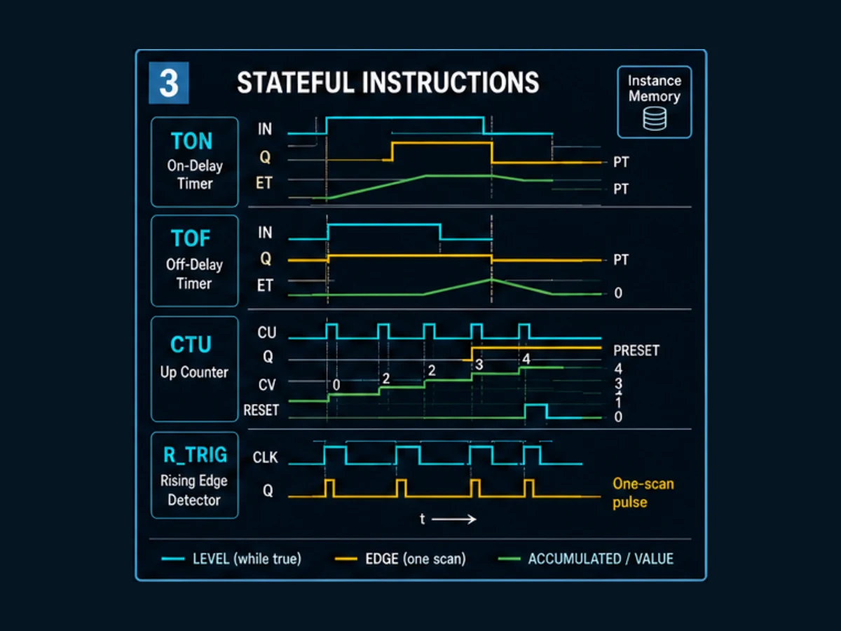
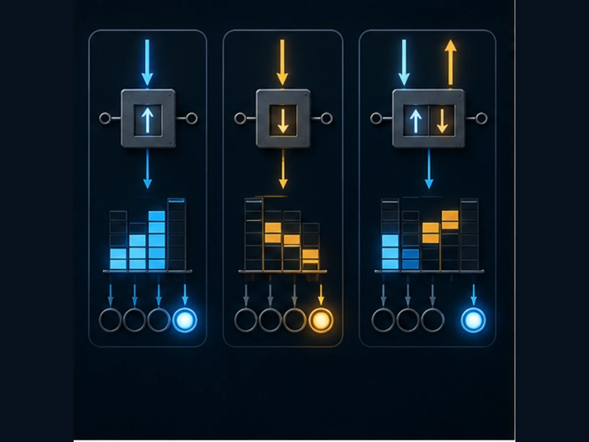
A PLC counter is stateful logic that changes a current value when a documented input event occurs. A count-up counter (CTU) normally increments on a false-to-true event at its count input and asserts a threshold output when the current value reaches or exceeds the preset. A count-down counter (CTD) decrements toward a defined boundary. An up/down counter (CTUD) has separate up and down event inputs plus reset/load behavior. Those names describe a model, not identical vendor syntax.
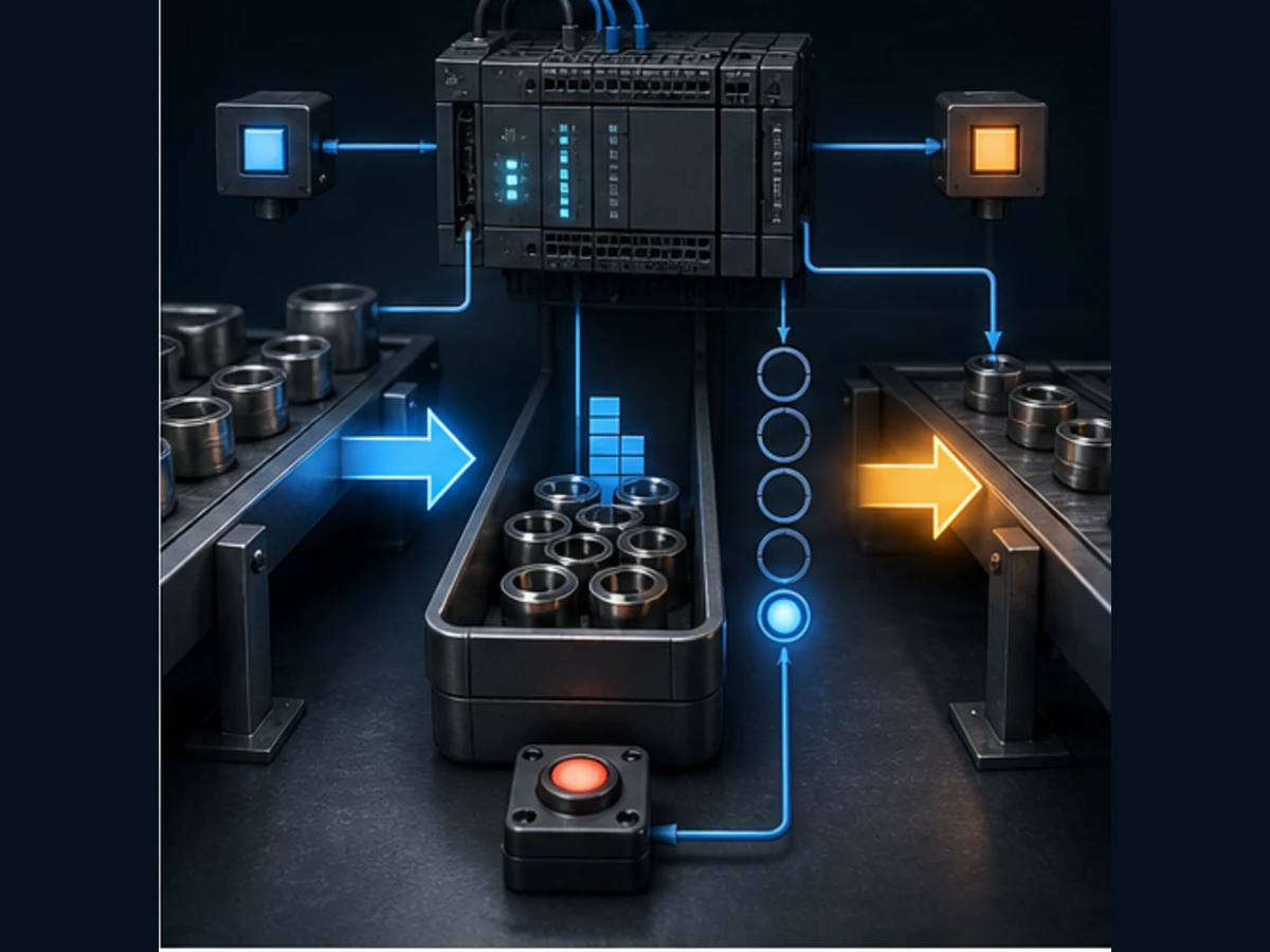
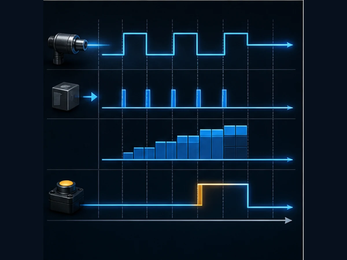
For a ten-product batch, create one AcceptedProductPulse, call one uniquely owned counter instance, set its preset to ten, use its Q or platform-equivalent status to request a sequence transition, and accept reset only under a defined new-batch condition. A photoeye held true across 20 scans should count once if the instruction is edge-sensitive. A photoeye that chatters through four false-to-true transitions can count four times. The reliable design therefore proves the whole path: physical event → electrical/raw input → qualified event → counter instance → threshold state → sequence action → field response.
Use an ordinary software counter only when the minimum valid high and low pulse durations remain observable through the input filter, I/O update, network where applicable, task/scan and instruction execution with margin. Use a documented high-speed counter, timestamp input or event task when pulses can occur between ordinary samples. A one-shot after a cyclic input cannot recover a pulse that was never sampled.
The saved production register records plc counters at 530 global and 40 United States monthly searches at KD 18. No later Mangools evidence is invented after credits were exhausted. This page owns broad counter selection, behavior, scan traces, use cases, high-speed handoff and cross-vendor translation. The Mitsubishi counter guide and Omron counter guide own those exact platforms; the CTU function-block reference owns compact runnable syntax/reference intent; and the edge/debounce guide owns deeper signal qualification.
| Requirement | Recommended starting model | State question | Critical test |
|---|---|---|---|
| count produced items from zero | CTU |
how many accepted events occurred? | one held input counts once |
| show remaining items | CTD or derived Target - Count |
how many remain? | zero and underflow boundary |
| track buffer entries/exits | CTUD |
current occupancy | simultaneous entry/exit and impossible negative/full states |
| total operating cycles | retained counter/extended total | lifetime events | restart, rollover and reset authority |
| encoder position/speed | hardware high-speed counter | pulse/phase count and rate | electrical extremes, direction, wrap and scaling |
| sequence step repeats | explicit state plus count | completed repetitions | reset and transition happen once |
Define the event before writing CTU
Start with an event contract
“Count products” is incomplete. Define which physical feature creates the event, when counting is enabled, which quality/permissive conditions qualify it and how closely products may arrive. For a conveyor:
| Field | Example contract | Why it matters |
|---|---|---|
| event | leading edge of carton at PE-101 | trailing edge or holes must not count |
| window | conveyor running feedback and FILLING state |
movement command alone is not proof |
| minimum on | 40 ms at fastest line speed | input/filter/task must observe it |
| minimum off | 30 ms between cartons | counter needs a new false state before next rise |
| rejected edges | sensor quality bad, maintenance test, count window closed | do not pollute production total |
| target | ten accepted cartons from current recipe | setting writer/range must be controlled |
| reset | accepted new-batch handshake while stopped at transition | operator button must not reset every scan |
| fault | command/run but no count progress within deadline | separate sensor/jam/flow diagnosis |
Download the PLC counter design contract and write these conditions before choosing a mnemonic.
Qualify without hiding signal defects
Create named layers:
RawProductEye
  -> InputHealthy
  -> StableProductState
  -> ProductInCountWindow
  -> AcceptedProductPulse
  -> BatchCounter
Filtering and debounce must be derived from measured valid/invalid durations. A 50 ms stability rule rejects a legitimate 40 ms product. A rising-edge block after a noisy qualified Boolean counts every remaining transition. Fix optics, mounting, wiring and filter first when they violate the signal requirement; do not turn every hardware defect into an opaque timer.
Understand CTU scan behavior
One false-to-true event increments once
This vendor-neutral example expresses intent:
BatchCount(
    CU := AcceptedProductPulse,
    R  := AcceptedBatchReset,
    PV := BatchTarget
);

BatchAtTarget := BatchCount.Q;
CurrentBatchCount := BatchCount.CV;
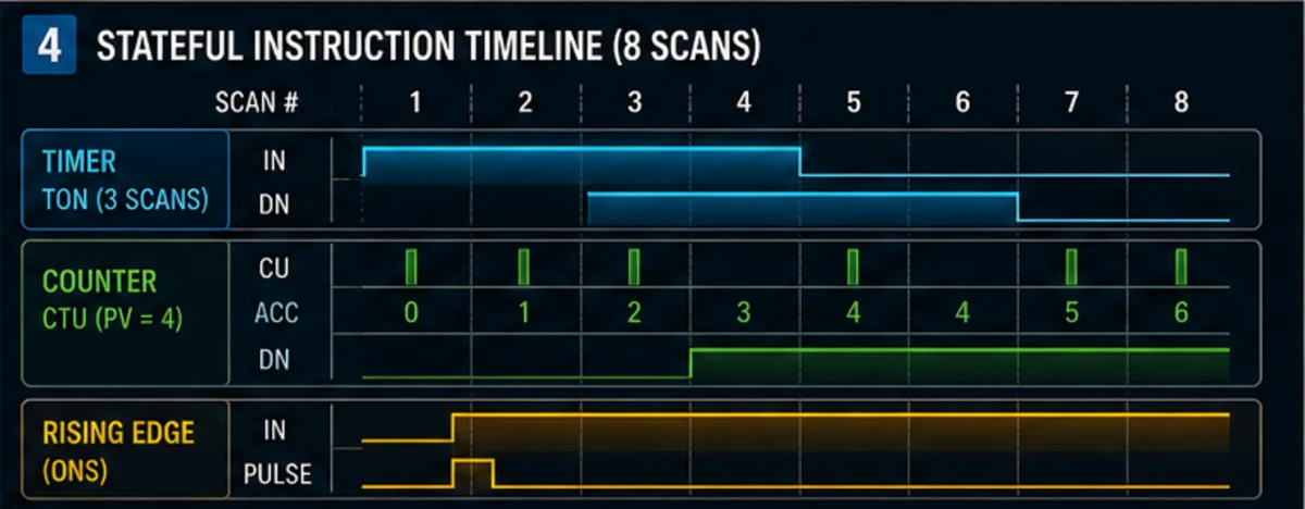
The exact declaration, call, names, data type and priority vary. Some ladder instructions include internal transition memory; some code paths require an explicit rising-edge instance. Do not add a one-shot automatically. Read the exact instruction help and test the four essential cases: false, first true, held true, and false-to-true again.
| Scan | Accepted input | Rising event | CV before | CV after | Q for PV=3 |
|---|---|---|---|---|---|
| 1 | 0 | no | 0 | 0 | 0 |
| 2 | 1 | yes | 0 | 1 | 0 |
| 3 | 1 | no | 1 | 1 | 0 |
| 4 | 0 | no | 1 | 1 | 0 |
| 5 | 1 | yes | 1 | 2 | 0 |
| 6 | 0 | no | 2 | 2 | 0 |
| 7 | 1 | yes | 2 | 3 | 1 |
Download the PLC counter scan-trace worksheet. Include actual scan/task time and raw input alongside the ideal edge.
Startup edge memory is platform specific
If the input is already true when the CPU starts, should it count? Rockwell's current Logix CTU documentation says prescan sets the count-up enable memory to prevent an invalid first-scan increment. Another IEC implementation can initialize differently depending on whether the instance executes, is retained or is re-created. Test cold/warm start, program enable/disable and skipped call paths.
A counter called conditionally may not update its edge memory while skipped. When execution resumes with input true, the result can differ by implementation. Prefer calling the instance in its designed task every cycle and gate the input explicitly unless the vendor documents another requirement.
Choose CTU, CTD or CTUD by the displayed meaning
CTU shows produced count naturally
Use CTU when operators and logic need the number already accepted. CV=7, PV=10 means seven produced and three remain. Completion becomes true at/above the target under common IEC behavior; confirm exact implementation and what happens beyond the target.
CTD can show remaining count
A CTD model typically loads its current value from PV, then decrements on count-down events and asserts a zero/boundary output. It can match an HMI that should show remaining products directly. The load action, output name and underflow behavior vary. An alternative is one CTU plus a bounded derived value Remaining = MAX(Target - CV, 0), which can reduce duplicated state.
CTUD owns one reversible value
Use CTUD for a buffer where entries increment and exits decrement. Define what simultaneous CU and CD edges mean. CODESYS Standard documents rising edges for each; current Rockwell CTUD documentation states count up executes before count down if both toggle in one scan. Those outcomes may produce the same net value but different transient/status/overflow evidence. Other platforms can define priorities differently.
| Boundary | Required decision |
|---|---|
| reset and load together | which wins, or is it invalid? |
| reset and count edge | does reset dominate? |
| load and count edge | load only, count after load or invalid? |
| CU and CD same scan | net zero, priority, both operations or fault? |
| CV at zero then CD | hold, underflow, wrap or diagnostic? |
| CV at maximum then CU | hold, overflow, wrap or diagnostic? |
| PV changes during run | immediate Q change, deferred recipe or rejection? |
Live mini-lab
Try it: press START, then STOP
A stop-dominant seal-in rung: START latches the motor output through its own contact, and STOP breaks the circuit.
Watch the output lamp: it stays on after START until you press STOP.
Free to start · runs in your browserOpens plcsimulationsoftware.com — same team
Design reset, load, retention and ownership
Give each counter one writer
A counter is memory. Calling one instance from two programs or sharing a Rockwell counter structure between instructions can corrupt transition memory and state. Mitsubishi also warns against duplicate ownership of device state, and Omron classic counters share numbered areas. Give each requirement one device/instance, one call location and one reset/load arbiter. Publish derived read-only tags for HMI and sequence consumers.
Reset should not erase evidence prematurely
For a batch:
- counter reaches target;
- sequence records completion and moves product;
- downstream feedback proves transfer/clear;
- next-batch request is accepted;
- reset establishes zero; and
- first new event is accepted only after reset release.
Do not drive reset continuously from “not running,” because that can erase a partial batch whenever a stop occurs. Do not let acknowledgement reset the production count if it is also needed as first-out evidence. Separate operator acknowledge, fault reset, batch reset and maintenance total reset.
Retention is more than the instruction name
Counter state is often retentive while its enabling rung is false, but persistence across program disable, CPU stop or power loss depends on platform memory configuration, instance storage, startup code and battery/nonvolatile behavior. Test each transition. Define whether the physical machine can reconcile a retained partial count; a retained value with product removed during outage can be wrong.
| Event | Required behavior to specify |
|---|---|
| count input false | hold current value or reinitialize? |
| sequence leaves counting state | retain for reporting or reset after handshake? |
| CPU stop/run | preserve, reset or reconcile? |
| power interruption | preserve only with verified retention or controlled recovery |
| recipe target changes | defer, accept or reject based on batch state |
| online edit/re-download | initialize edge memory and state predictably |
| maintenance reset | role, reason, timestamp and prior value recorded |
Build reliable batch and buffer examples
Batch count with one state transition
Keep the counter away from the final physical output. Its completion requests a sequence transition; the state machine owns commands and verifies feedback. This prevents BatchCounter.Q from directly energizing a diverter in several places.
AcceptedProductPulse -> BatchCounter

IF State = FILLING AND BatchCounter.Q THEN
    NextStateRequest := TRANSFER;
END_IF;

DiverterCommand := (State = TRANSFER)
                   AND DiverterPermissive
                   AND NOT TransferFault;
Run Structured Text in the simulator
Test exact target, one over target, late completion, downstream failure, stop/restart and reset denial while product remains in the sensor.
Buffer occupancy with conservation evidence
For entries and exits, the count should agree with physical occupancy within known sensor zones. Add plausibility:
- entry while full is a fault or rejected event;
- exit while empty is a fault or reconciliation event;
- both sensors true requires defined geometry;
- missed pulse produces disagreement with a downstream/independent reference;
- restart requires an inventory or homing strategy.
Do not silently clamp CV between zero and capacity; that hides the event that violated conservation. Preserve a first-out code and the raw/accepted edge history.
Select ordinary versus high-speed counting
Calculate the complete observation budget
Start from worst-case physical pulses. For a wheel encoder with P effective counts per revolution and maximum speed N rpm:
PulseFrequencyHz = P × N / 60
The minimum high and low widths depend on duty cycle and signal method. Compare them with sensor/encoder output, cable/interface, input threshold, configurable filter, I/O update, network update if remote, task interval, phase and jitter. Average line rate is not enough.
An ordinary cyclic path needs margin for both true and false states to be observed. If the pulse can begin and end between samples, use target-supported hardware capture. Reducing task period blindly can consume CPU and create scheduling faults without fixing electrical filtering.
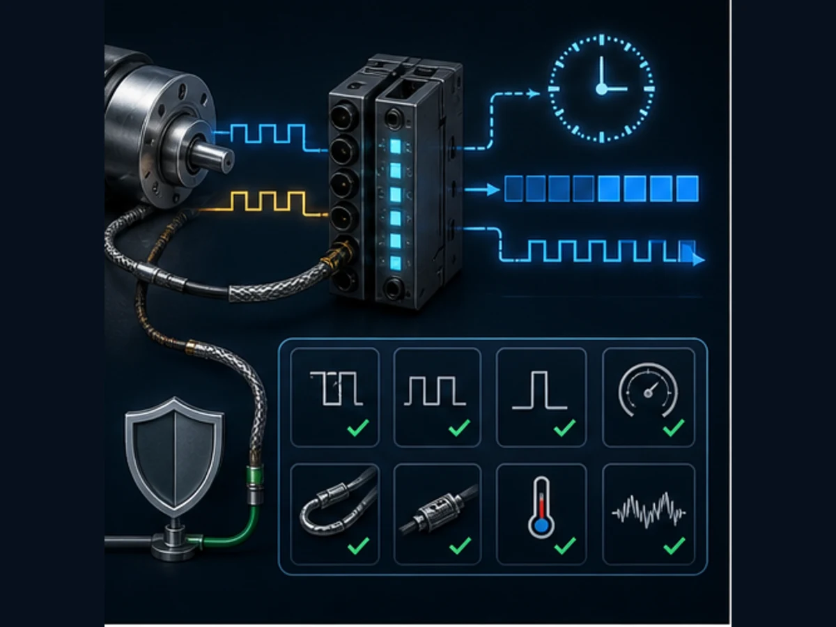
A high-speed counter is a subsystem
A hardware HSC needs:
| Layer | Evidence |
|---|---|
| electrical | signal type, voltage, common, shielding/bonding and measured waveform |
| mode | one-phase, pulse/direction, CW/CCW, A/B and optional Z/reference |
| limits | active-channel frequency, high/low width, phase and simultaneous-use rules |
| configuration | terminal assignment, filter, preset/compare, latch/reset and module parameters |
| data interface | count datatype, status/quality, update and task consumption |
| engineering units | effective edges/revolution, gearing, sign, zero and wrap arithmetic |
| diagnostics | missing pulses, implausible rate, direction mismatch and channel/module faults |
| validation | generator/encoder tests from slow through maximum credible rate |
Handle ranges, overflow and rollover deliberately
Know the current-value datatype
Counter implementations use different datatypes and boundary behavior. CODESYS Standard documents a WORD-based counter family and notes a type difference from the IEC standard model. Current Logix CTU uses a DINT accumulator and documents overflow/underflow bits with wrap behavior at signed limits. Siemens counter blocks support selected integer types in target-specific contexts. Mitsubishi and Omron have generation-specific device representations.
Never assume a universal 32-bit signed range. Record type, minimum, maximum, comparison rule and what happens past the boundary. For lifetime totals, archive and extend the value before rollover. For position, use modular delta math. For buffer occupancy, treat boundary violation as diagnostic evidence rather than wrapping.
Preset changes can alter status immediately
If CV=8 and an HMI changes PV from 10 to 6, common CV >= PV behavior makes completion true without a new product edge. Decide whether a running batch may accept the change. A robust recipe manager validates range/type, stages the value and applies it at a batch boundary with old/new audit evidence.
Translate counter logic across vendors
Preserve behavior, not mnemonic spelling
| Platform example | Common ordinary model | Important non-portable evidence |
|---|---|---|
| Rockwell Logix | ladder CTU/CTD with COUNTER; FBD/ST CTUD uses another structure |
prescan transition memory, .ACC/.PRE/.DN/.OV/.UN, RES and shared-tag warnings |
| Siemens S7 | IEC counter instruction with an instance DB and selected value type | instance retention, task/OB call, reset/load priority and optimized access |
| CODESYS | Standard library CTU/CTD/CTUD instances |
library version, WORD type note, call and task/retain configuration |
| Mitsubishi FX | C-device instructions and current FX5 standard FBs; separate HSC resources | family/device allocation, latch settings, special inputs and instruction model |
| Omron CP/CJ/CS | CNT/CNTX traditionally count down toward zero |
BCD versus binary setting and numbered shared C-area state |
| Omron NJ/NX | named CTU/CTD/CTUD instances |
typed instance, task and reset/load interface |
Rockwell ladder CTU and IEC CTU share an up-count concept but not one source-compatible block. Traditional Omron CNT counts down, so translating it to CTU can reverse the operator meaning. An FX3 high-speed C number is a hardware allocation, not merely a counter variable. Write a behavior table and run the same edge/reset/restart/range tests on source and target.
Troubleshoot the first failed boundary
Capture before reset
Record physical event, raw electrical/input state, input quality/filter, accepted pulse, task/program route, instance/current value, preset, completion, reset/load, sequence state, output/feedback and force/test state. Then stop at the first mismatch.
| Symptom | First useful comparison | Common causes |
|---|---|---|
| double count | physical/raw edges vs accepted pulses | bounce, vibration, holes, noise, repeated program call |
| missed count | pulse width/gap vs complete acquisition budget | filter, scan/update, gating, HSC configuration |
| counter never changes | accepted pulse vs actual instance execution | wrong program/task, reset held, duplicate/wrong instance |
| Q never true | CV/PV/type and exact comparison behavior | wrong setting source, data representation, overwrite |
| Q true but machine does nothing | sequence transition, command, output and feedback | ownership/interlock/field problem, not counter |
| count resets unexpectedly | every reset/load writer and restart code | HMI held request, startup routine, shared instance |
| count wrong after restart | retain/latch configuration and physical reconciliation | assumed persistence or stale partial batch |
| negative/huge jump | datatype, underflow/overflow and modular math | range crossing, sign conversion, HMI mapping |
Acceptance tests before release
Download the PLC counter acceptance matrix. Run at least:
- initial/reset value and status;
- one clean edge increments/decrements once;
- held input creates no repeat event;
- second edge after a valid false interval counts;
- bounce/noise below rejection threshold does not count;
- minimum valid pulse is captured with margin;
- maximum credible rate has no missing/extra events;
- just below, exactly at and above preset status;
- reset plus count in one execution;
- load plus count and reset plus load where supported;
- simultaneous up and down events;
- preset changes below/equal/above current value;
- zero, maximum, underflow, overflow and rollover;
- disabled/skipped call and re-enable with input true;
- warm/cold restart and power interruption;
- HMI mapping, authorization and audit trail;
- sequence output, field feedback and process response; and
- force/test removal, project compare, backup and rollback.
PLC counter answer map
| Question | Concise answer |
|---|---|
| What does CTU do? | increments current value on documented rising events and commonly sets Q/DN at the preset |
| Does a counter count every scan? | an edge counter should count once per accepted false-to-true event |
| What is CTD for? | count-down or remaining-count behavior with a defined load/boundary model |
| What is CTUD for? | one current value updated by separate up and down events |
| Why are counts duplicated? | repeated physical/raw edges, duplicate execution or shared state owner |
| Why are fast pulses missed? | the cyclic acquisition path never observes a valid high/low state |
| When is HSC needed? | when measured pulses cannot be captured by ordinary I/O/task with margin |
| Is counter state retentive? | only as documented and tested for rung false, stop/run and power loss |
| Can counters copy between vendors? | migrate event, state, priority, range and restart behavior, not mnemonic alone |
| Can simulation validate an encoder? | no; it can validate logic, not electrical pulses, phase, mechanics or hardware capture |
Frequently asked questions
What is a PLC counter?
A PLC counter is stateful logic or hardware that changes a current value on defined events and exposes threshold/status outputs. Its input event, reset/load, datatype, range, retention and task/hardware path must be specified.
How does a CTU counter work?
CTU normally increments once when its count-up input changes from false to true. It retains the current value between events and commonly makes Q or a done bit true when current value reaches/exceeds preset. Exact startup, range and reset behavior are vendor specific.
What is the difference between CTU and CTD?
CTU naturally represents events accumulated upward from zero. CTD naturally represents a value loaded from a preset and decremented toward a boundary. Choose based on the state readers need, then verify the target block's load/reset and threshold outputs.
What is a CTUD counter?
CTUD has separate rising-event inputs for increment and decrement, one current value, and reset/load controls. It is useful for buffer occupancy or reversible counts only after simultaneous events, limits and reconciliation are defined.
Does a PLC counter count while its input stays on?
An edge-sensitive counter should change once when the input first becomes true and not again until it becomes false and rises again. Confirm the exact instruction; a separate arithmetic increment executed every scan behaves differently.
Why does my PLC counter count twice?
Check whether the physical sensor or raw input produced two transitions, qualification chattered, the same instance executed twice or another instruction shared/overwrote its state. Correlate waveform, raw input, accepted event and current value.
Why does my PLC counter miss fast pulses?
The input filter, I/O or network update, task period and phase may not observe the pulse's high and low states. Measure minimum width/gap and use a documented high-speed counter or capture feature when cyclic margin is insufficient.
How do I reset a PLC counter?
Use the target instruction's reset input/instruction through one authorized arbiter. Define the allowed machine state, preserve required batch/fault evidence, and test reset with a simultaneous count event and a held operator request.
Are PLC counters retentive?
They often retain current value while the count input is false, but CPU stop/power-loss persistence depends on the platform, memory/instance configuration and startup code. Test the exact target and define physical reconciliation.
What happens when a PLC counter overflows?
It may set an overflow status, wrap, saturate or behave according to a device-specific limit. Record datatype and documented boundary, then test it. Do not allow production totals or positions to reach rollover without a design.
When should I use a high-speed counter?
Use one when the fastest valid pulses cannot be observed reliably by ordinary input filtering, update and task execution, or when phase/direction/latch/compare behavior is required. Select exact electrical and performance specifications from the hardware manual.
Are CTU counters identical across Rockwell, Siemens, CODESYS, Mitsubishi and Omron?
No. They share concepts but differ in structures/instances, types, range, prescan/startup, reset/load priority, language availability, retention, overflow and hardware integration. Traditional Omron CNT even counts down toward zero.
Can a browser counter simulator replace vendor software?
No. It can practise accepted edges, held input, reset, threshold and diagnosis. It cannot validate target syntax, compiler/library, task, retention, input filter, high-speed hardware, electrical signal, machine, process or safety behavior.
Primary sources and review trail
- IEC, IEC 61131-3:2025 publication record. Current PLC programming-language and function-block standard scope.
- Rockwell Automation, Studio 5000 Logix Designer v38 CTU help. False-to-true behavior, structure, prescan, overflow/underflow and warnings.
- Rockwell Automation, Studio 5000 timer and counter instruction index. Language/model routing and RES context.
- Rockwell Automation, Studio 5000 CTUD help. Up/down ordering, structures, reset and execution.
- Rockwell Automation, SLC 500/MicroLogix instruction reference. Installed-base CTU scan/frequency context; do not generalize to Logix.
- CODESYS, Standard library CTUD reference. Rising edges, reset/load, QU/QD/CV and WORD type note.
- CODESYS, Standard counter index. CTU, CTD and CTUD library owner.
- Siemens, S7-1200 current manual/document portal. Resolve current CPU/TIA IEC counter type, instance and retention details.
- Siemens, TIA Portal instruction manual search. Resolve exact release and target behavior.
- Mitsubishi Electric, FX3 programming manual. FX ordinary and high-speed counter device behavior.
- Mitsubishi Electric, current FX5 instruction/standard-FB manual. Current FX5 counter and CTU/CTD/CTUD paths.
- Omron, CP1E/CP2E Instructions Reference W483. Traditional CNT/CNTX decrementing and reset/representation behavior.
- Omron, NJ/NX Instructions Reference W502. Sysmac CTU/CTD/CTUD typed-instance behavior.
- NIST, SP 800-82 Rev. 3. OT access, change, backup and recovery context.
- OSHA, Control of hazardous energy. US servicing energy-control boundary where applicable.
- PLC Programming IO, Mitsubishi counter guide. Versioned Mitsubishi specialist with its own primary-source trail.
- PLC Programming IO, Omron counter guide. Versioned Omron specialist with its own primary-source trail.
- PLC Programming IO, PLC scan-cycle guide. Cross-vendor timing/sampling specialist.
Use the current target instruction help, hardware manuals, controlled project, I/O drawings, process requirement, risk assessment and site procedure. This guide is not a universal syntax sheet, electrical design or safety validation.
Counter implementation checklist
- Physical event and valid/invalid pulse durations are measured.
- Input filter/update/task path can capture events with margin, or HSC is selected.
- CTU/CTD/CTUD/device/HSC choice matches the state question.
- One device/instance and one call/write owner are documented.
- Setting, current value, datatype, range and rollover policy are explicit.
- Reset/load/simultaneous-event priorities are tested.
- Startup, disabled call, stop/run and power-loss behavior are tested.
- HMI writes, reset roles, audit and recipe boundary are controlled.
- Threshold drives a sequence request, with output and feedback proven separately.
- Normal, boundary, fault, restart, high-rate and rollback tests are retained.
A dependable counter is not a box labeled CTU. It is a measured event contract, one state owner, known execution semantics and a complete acceptance record from sensor to process result.
Now run it · free to start
Run a CTU counter in your browser
Pulse the input, watch the accumulated count reach the preset and reset it — CTU, CTD and CTUD with timing diagrams. Free, nothing to install.
Ownership disclosure: PLC Programming IO and PLC Simulation Software are operated by the same publisher.
PLC Programming IO Editorial Team
Industrial automation education, references, and software testing
The PLC Programming IO Editorial Team publishes sourced industrial-automation education and documents how material is reviewed, tested, and corrected. A team byline means the publisher is responsible for the page; it does not represent a fictional person or imply an engineering licence.
Coverage:
- • PLC programming concepts and examples
- • Vendor software tutorials and comparisons
- • SCADA, HMI, protocols, and instrumentation
- • Training, careers, and reference material
Review standard:
- • Prefer primary and official sources
- • Record software versions when material
- • Separate tested facts from estimates
- • Publish material corrections
Important scope note
This site provides education, not project-specific engineering approval. Safety, code, and compliance decisions require a qualified person with access to the actual machine and jurisdiction.