PLC Edge Detection, Debounce and Hysteresis: Code and Scan Traces
Condition noisy digital and analog PLC signals with hardware filters, symmetric debounce, rising/falling edges and hysteresis, then prove startup, timing and missed-pulse behavior with executable Structured Text and 20 tests.
Review status: Editorially reviewed against current IEC 61131-3:2025 scope material, CODESYS Standard and Util library documentation, current Rockwell Studio 5000 bit-instruction help, current Siemens S7-1200 V4.7 system-manual input-filter and pulse-catch behavior, Beckhoff TwinCAT and Schneider Electric Machine Expert trigger/hysteresis references plus current sensor terminology; exact input circuit, module filter, process image, task, instruction/library, prescan, restart, pulse-capture, HSC, online-change, safety and target timing behavior require controller-specific verification
Direct answer
Use debounce, edge detection and hysteresis for different PLC signal problems:
- Debounce accepts a Boolean state only after it remains continuously stable for a defined time. Use it for contact bounce, flicker or a minimum valid ON/OFF duration.
- Rising/falling edge detection compares the current qualified Boolean with its previous executed state to create a one-task-execution event. It prevents a held signal from triggering an action every scan.
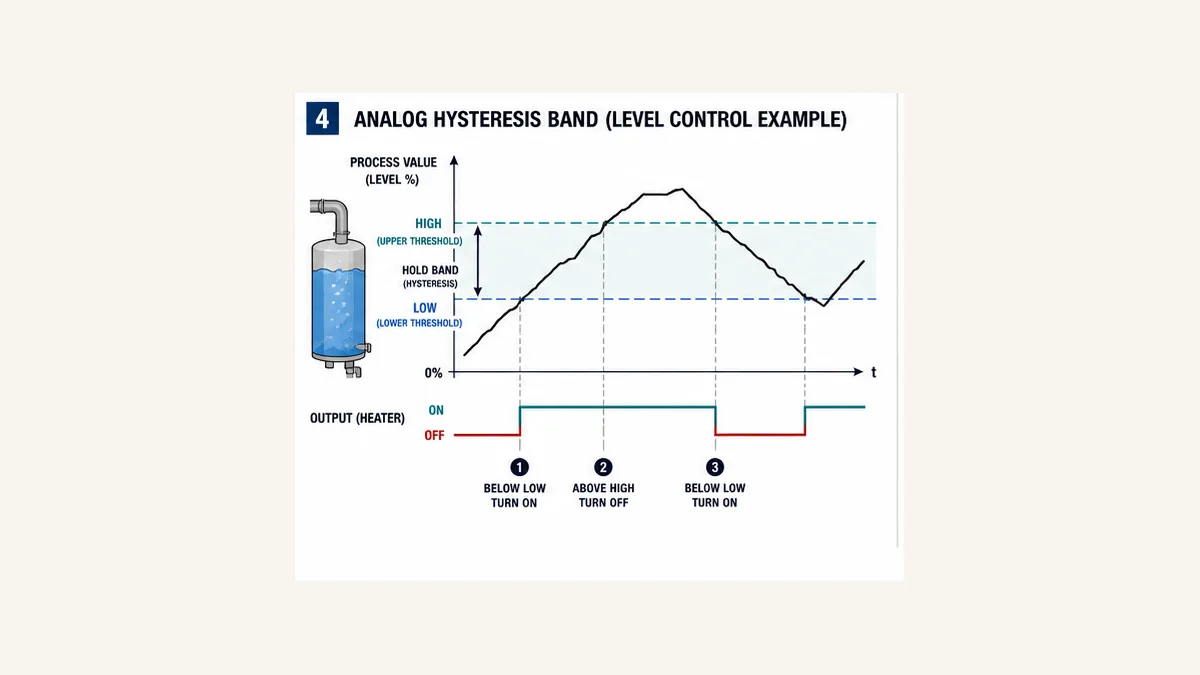
- Hysteresis uses separate switch-on and switch-off thresholds. Inside the band, it retains the prior state so a noisy analog value does not chatter around one threshold.
Apply them in the right order: physical signal → module filter/capture → task sample → software qualification → edge detector → event consumer. An edge detector does not debounce; it faithfully produces an event for every false-to-true transition it sees, including bounce. A debounce timer does not recover pulses the module or cyclic task never sampled. Hysteresis does not prove analog quality. Each layer changes timing and needs its own evidence.
A reusable design must define both directions, equality at thresholds, first-call state, task-call continuity, disable/re-enable behavior, restart/download behavior, shortest valid pulse, maximum acceptable response delay and what happens when quality is bad. For a safety input or protective function, use the certified hardware, parameters, application rules and validation method—never credit an ordinary program debounce as safety response.
Download the signal-conditioning contract, 20-test acceptance matrix and vendor-neutral IEC Structured Text example.
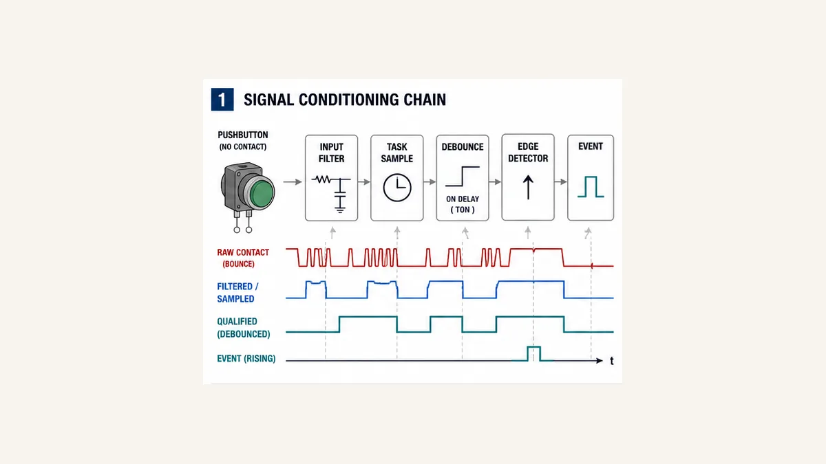
Choose the mechanism from the requirement
Filtering, debounce, edge detection and hysteresis are not synonyms
Start by writing the event requirement in measurable language. “Fix the noisy sensor” is not a design requirement. “Accept ON only after 20 ms continuously true, accept OFF only after 15 ms continuously false, then count one event on each qualified rising transition” is testable.
| Requirement | Primary mechanism | State/memory | Timing consequence | Main failure if misused |
|---|---|---|---|---|
| reject electrical spikes before the process image | configurable input-module filter | module-specific | delays or rejects both edges according to hardware | a valid short pulse disappears before the program |
| capture a pulse shorter than the cyclic sampling interval | pulse catch, hardware interrupt or high-speed counter | hardware/configuration-specific | response and limits come from module/CPU | ordinary task never observes the pulse |
| require continuous Boolean stability | symmetric software debounce | on/off timers plus qualified state | explicit pickup/dropout delay | timer hides a loose wire or blocks valid events |
| perform one action when a state becomes true | rising edge / one-shot | previous executed state or vendor storage operand | event exists for one execution | bounced input generates several events |
| perform one action when a state becomes false | falling edge / one-shot | previous executed state or vendor storage operand | event exists for one execution | startup/prescan semantics surprise the design |
| stop analog chatter near a setpoint | low/high hysteresis | prior output state | different pickup and dropout values | bad signal remains plausible inside the band |
| smooth analog noise | justified digital or module filter | filter history | phase lag and amplitude change | a real fast change or diagnostic spike is hidden |
The same physical sensor can need more than one layer. A mechanical limit switch may use a module filter to reject microsecond electrical noise, a software qualifier to require 30 ms stable travel and a rising edge to increment a sequence once. Document the total delay rather than describing each parameter independently.
Fix physical defects before tuning software
First inspect supply, common/reference, shielding/grounding, cable routing, connectors, sensor alignment, target geometry, contamination, vibration, leakage current, input thresholds and module diagnostics. Capture the raw terminal and input waveform with equipment and procedures appropriate to the circuit.
Debounce is legitimate when bounce or minimum persistence is part of the interface contract. It is not a permanent repair for a loose terminal, failing relay contact, unstable target, damaged cable or incorrect source/sink wiring. Retain a raw-transition count or diagnostic trace when practical so a “stable” qualified signal does not conceal worsening hardware.
The sampled-data timing model
The PLC program cannot detect a state it never receives
A physical edge passes through several clocks and delays:
- the sensor/output response and contact or electrical behavior;
- the input circuit and configurable module filter;
- remote-I/O network update where applicable;
- process-image or direct-input update;
- cyclic or event-task release, priority and jitter;
- software debounce recognition;
- edge detector execution; and
- the consumer routine and output update.
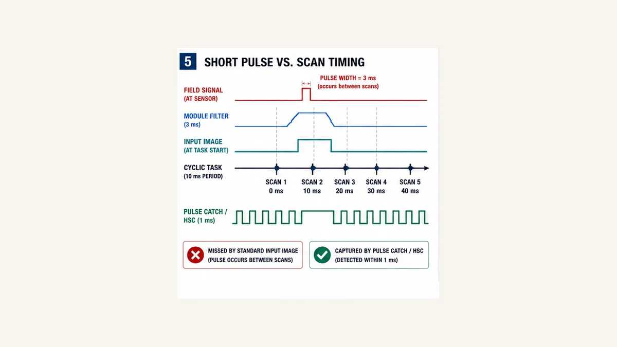
Do not assume “10 ms task” means every 9 ms field pulse is detected. Phase matters: a pulse can rise just after one sample and fall just before the next. Input filtering can shorten, delay or completely reject what reaches the task. Remote I/O and process-image updates can add independent phase and jitter.
For ordinary cyclic observation, derive the shortest detectable pulse from the exact component chain and prove it with a pulse-width/phase sweep. When the required pulse is too short or the count rate too high, use the controller’s supported pulse catch, edge event/hardware interrupt or high-speed-counter path—not an optimistic software one-shot.
Worked latency budget
Assume a non-safety entry sensor has:
- measured minimum valid ON time: 35 ms;
- module input filter: 3.2 ms;
- fixed cyclic task period: 10 ms for the simplified calculation;
- software ON debounce: 20 ms; and
- no remote-I/O phase or extra preemption in this teaching case.
After the filtered point changes, the task sees it between approximately zero and one task period later. The timer then reaches 20 ms only on an execution that calls it. A simplified recognition range is therefore roughly:
earliest qualified edge ≈ 3.2 ms + 0 ms sample phase + 20 ms = 23.2 ms
latest qualified edge   ≈ 3.2 ms + 10 ms sample phase + 20 ms = 33.2 ms
That is not a universal formula. Some input-image schedules, timer implementations, task jitter, remote networks and output stages add more uncertainty. The example does expose the central tradeoff: a 20 ms software debounce fits inside the 35 ms measured valid pulse only with 1.8 ms nominal margin at the simplified worst phase. That margin is probably too small after real uncertainties are included. Reduce only a justified filter, choose a longer-valid sensing geometry, use supported capture, or redesign the timing requirement.
| Budget term | Minimum | Maximum used | Evidence |
|---|---|---|---|
| sensor and input transition | project-specific | project-specific | sensor/module trace |
| hardware filter | configured/model behavior | configured/model behavior | module manual plus pulse test |
| input image/network phase | 0 | measured/design bound | timestamps and architecture |
| task sampling | 0 | period plus jitter bound | task statistics |
| software stability | exact setting | setting plus execution quantization | raw/timer/qualified trace |
| event consumer/output | same execution or later by design | scheduled bound | execution/order trace |
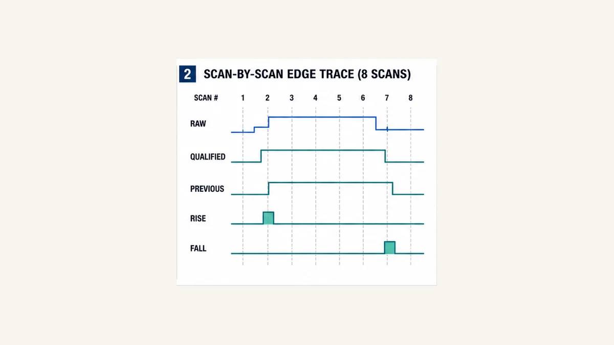
Rising and falling edge detection by scan
The transferable Boolean equations
For a qualified Boolean Q and its previous executed state Q_prev:
Rise = Q AND NOT Q_prev
Fall = NOT Q AND Q_prev
Q_prev := Q        // update after calculating both events
The update order is part of the behavior. If Q_prev is overwritten before Rise and Fall are evaluated, both events remain false. If two routines write or share the history bit, the result depends on execution order. Give one edge detector one storage instance and one task owner.
An IEC-style R_TRIG or F_TRIG is a stateful function block instance. CODESYS, Beckhoff and Schneider documentation describe R_TRIG as producing Q for one execution/cycle after a false-to-true input transition. Rockwell separates ladder ONS, ladder OSR/OSF and function-block input variants; its storage/prescan behavior is vendor-specific. Similar intent does not make those instructions syntax- or startup-equivalent.
Eight-scan trace
Assume the qualified input begins false, rises in scan 3, stays true through scan 6 and falls in scan 7:
| Scan | Qualified before edge | Previous before update | Rise | Fall | Previous after update |
|---|---|---|---|---|---|
| 1 | 0 | 0 | 0 | 0 | 0 |
| 2 | 0 | 0 | 0 | 0 | 0 |
| 3 | 1 | 0 | 1 | 0 | 1 |
| 4 | 1 | 1 | 0 | 0 | 1 |
| 5 | 1 | 1 | 0 | 0 | 1 |
| 6 | 1 | 1 | 0 | 0 | 1 |
| 7 | 0 | 1 | 0 | 1 | 0 |
| 8 | 0 | 0 | 0 | 0 | 0 |
The rising event is one execution, not necessarily one fixed wall-clock millisecond. In a 10 ms cyclic task it may be visible for roughly one task interval to other logic in the same context; asynchronous tasks, communications and HMI scans may never display it. If another layer must observe the event, use an event counter, timestamp, sequence number or acknowledged latch rather than stretching a pulse casually.
Live mini-lab
Try it: press START, then STOP
A stop-dominant seal-in rung: START latches the motor output through its own contact, and STOP breaks the circuit.
Watch the output lamp: it stays on after START until you press STOP.
Free · no signup to try · runs in your browserOpens plcsimulationsoftware.com — same team
Symmetric debounce with separate ON and OFF timing
Debounce the state, then detect its edge
A symmetric qualifier has four conceptual states:
StableOff: output false; wait for raw true;TimingOn: raw must remain true forOnDelay; any false resets the attempt;StableOn: output true; wait for raw false; andTimingOff: raw must remain false forOffDelay; any true resets the attempt.
This is continuous stability, not retentive accumulation. Five separate 4 ms spikes must not add up to a 20 ms ON qualification. A standard non-retentive on-delay timer naturally resets when its IN becomes false, subject to exact target semantics.
Separate ON and OFF values are often necessary. A part-present sensor may need a longer ON time to reject reflections but a shorter OFF time to separate adjacent products. Motor feedback may need short pickup debounce and a longer dropout delay through expected contact transfer. Record the process reason; asymmetric numbers copied from an old project are not evidence.
Executable vendor-neutral Structured Text pattern
The downloadable example includes initialization and disable handling. The core execution is:
onTimer(IN := Raw AND NOT Qualified, PT := OnDelay);
offTimer(IN := NOT Raw AND Qualified, PT := OffDelay);

IF onTimer.Q THEN
    Qualified := TRUE;
ELSIF offTimer.Q THEN
    Qualified := FALSE;
END_IF;

Rise := Qualified AND NOT previous;
Fall := NOT Qualified AND previous;
previous := Qualified;
Run Structured Text in the simulator
Call the function block every execution of one defined task. Give each physical/logical signal its own instance. Confirm TON, TIME, instance, initialization, online-change, retain and download behavior on the exact controller and library. This source is a design example, not a universal import file.
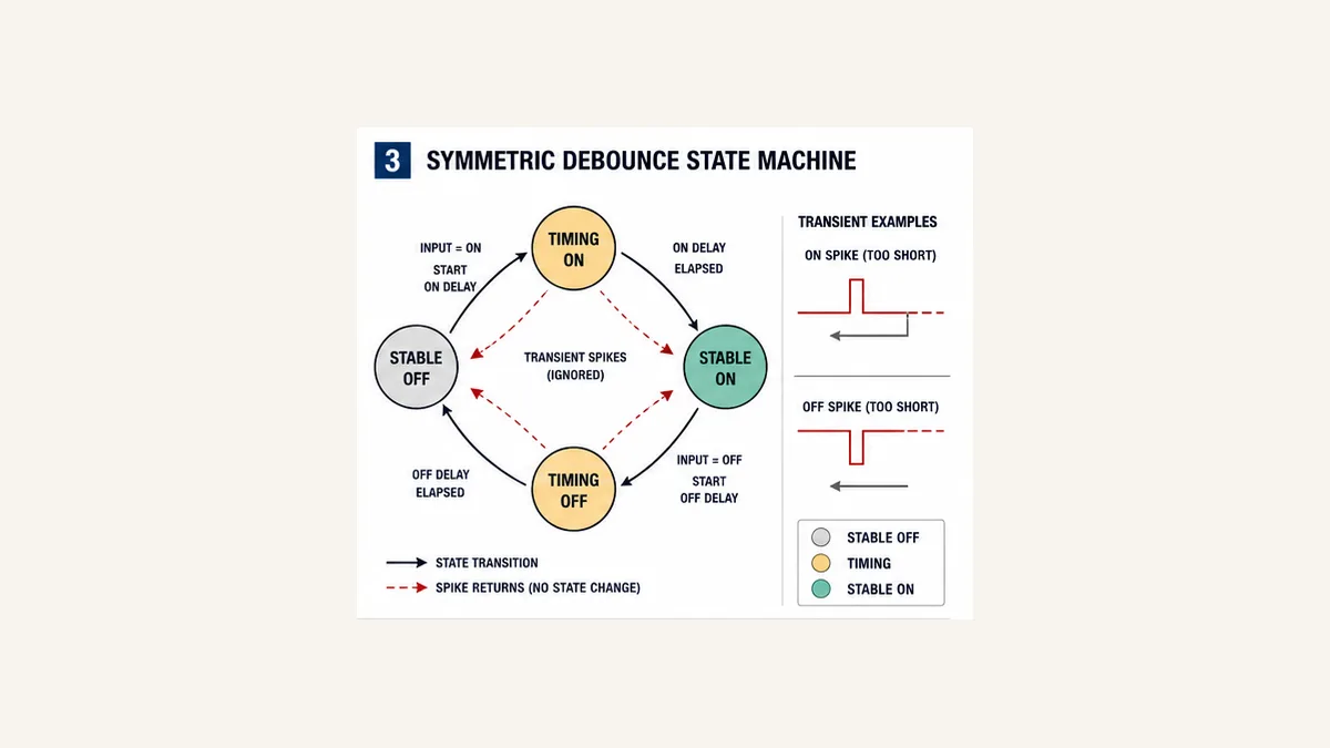
Debounce scan trace with chatter
For a 10 ms task and OnDelay := T#20ms, the exact timer boundary must be tested on the target. The intended logical trace is:
| Execution | Raw | Qualified entering | ON timer intent | Qualified leaving | Rise |
|---|---|---|---|---|---|
| 1 | 0 | 0 | reset | 0 | 0 |
| 2 | 1 | 0 | starts | 0 | 0 |
| 3 | 0 | 0 | resets before qualification | 0 | 0 |
| 4 | 1 | 0 | starts new continuous attempt | 0 | 0 |
| 5 | 1 | 0 | continues | 0 | 0 |
| 6 | 1 | 0 | reaches tested threshold | 1 | 1 |
| 7 | 1 | 1 | reset/not needed | 1 | 0 |
Do not force an assumed execution count into the requirement. Express the requirement in elapsed time, then test just below, at and just above the threshold across multiple phases relative to task execution.
Analog hysteresis with explicit equality and quality
Hysteresis is retained state inside a band
For a heater or fill request that turns on when the process value is low and turns off when it is high:
if PV <= Low:       StateOn_next = true
else if PV >= High: StateOn_next = false
else:               StateOn_next = StateOn_previous
Require Low < High. In this defined policy, equality at Low turns ON and equality at High turns OFF. Other products or process requirements may use strict comparisons. State the choice and test exact equality, integer/real conversion, NaN or invalid values where supported, scale limits and bad quality.
The same value inside the band can produce either state. At 50% with Low = 30% and High = 80%, the heater remains ON if the level entered the band from below and remains OFF if it entered from above. That path dependence is intentional memory, not a nondeterministic bug.
| PV path | Previous state | Result | Reason |
|---|---|---|---|
| drops to 29.9% | OFF | ON | below Low |
| rises to 50% | ON | ON | hold prior state inside band |
| rises to exactly 80% | ON | OFF | defined High equality |
| drops to 50% | OFF | OFF | hold prior state inside band |
| drops to exactly 30% | OFF | ON | defined Low equality |
| quality bad at any value | either | explicit project reaction | value alone is not trustworthy |
Do not automatically force every bad analog input low or high. The safe/operational reaction depends on the process: hold last command for a bounded time, turn an ordinary output off, switch to a validated fallback, alarm and inhibit automatic control, or execute another designed response. Separate ordinary process control from independent alarms, trips and safety functions.
Value hysteresis versus time hysteresis
Value hysteresis requires the measured value to cross a different reset threshold. Time qualification requires the condition to remain true for a duration. They solve different instability:
| Pattern | Example | Use | Hidden cost |
|---|---|---|---|
| value only | high alarm picks at 80%, clears below 78% | analog noise around a threshold | alarm can remain active indefinitely inside band |
| time only | high condition must persist 2 s | brief excursions are not actionable | a real fast hazard may be delayed |
| value plus pickup delay | above 80% for 2 s, clear below 78% | noisy process with persistence requirement | combined activation delay must fit consequence analysis |
| pickup and dropout delays | ON after 50 ms, OFF after 100 ms | Boolean chatter with asymmetric persistence | stale ON/OFF can mask device failure |
Specify alarm deadband/delay separately from the control hysteresis when they serve different objectives. An operator alarm should not disappear merely because a control output changes state unless that coupling is explicitly designed.
Startup, restart and execution-order traps
First call is a design case
What should happen if the raw input is already true when the PLC enters RUN? At least four policies exist:
| Policy | Behavior | Appropriate when | Risk |
|---|---|---|---|
| initialize false then qualify | wait full ON delay, then generate a rise | new authorization is required after restart | delays recognition of an already-active fact |
| initialize to raw without edge | qualified adopts current raw; no synthetic event | state monitoring where restart must not recount | can accept an unstable startup input |
| restore qualified/history | continue retained state under controlled restart | continuity is required and proven | stale retained state can conflict with field |
| inhibit until explicit synchronization | expose unknown and require validation | multi-system state must reconcile | more complex recovery workflow |
The downloadable block uses an explicit Initialize and InitialState. Its default design must be wired deliberately. Do not rely on implicit zeroing, prescan or a library’s first-call behavior unless exact target evidence makes that the approved policy.
Conditional calls freeze hidden memory
Do not place an R_TRIG, TON or debounce block inside a branch that sometimes skips its call unless the frozen-state behavior is intentional and tested. Example:
- edge block last executes while input false;
- its entire routine is disabled;
- physical input becomes true while disabled;
- routine is re-enabled;
- the stale previous state creates a delayed “new” rising edge.
Call the stateful block continuously and gate its event output, or implement explicit disable alignment. In the provided example, disable resets timers, holds the qualified state and aligns previous history with that state so re-enable alone does not create a deferred edge. A changed raw input can still begin a new qualification after re-enable.
Multiple tasks and writers create races
An input mapped into a fast task and a slow task can be sampled at different moments. Sharing one edge-history bit across both makes the faster task consume a transition before the slower task sees it. Generate the event in one owning task; transfer it through a counter, sequence number, queue or acknowledged handshake appropriate to the receiving task.
Likewise, do not write Qualified or the edge pulse from multiple routines. Cross-reference the raw tag, qualifier state, timer instances, previous state, events, counters and consumers.
Vendor instruction map and portability
Similar names do not guarantee identical startup behavior
| Platform/family | Common edge surface | Memory form | Portability question |
|---|---|---|---|
| IEC/CODESYS Standard | R_TRIG, F_TRIG |
function-block instance | library version, first call, task call continuity |
| Beckhoff TwinCAT | R_TRIG, F_TRIG in Tc2_Standard |
FB instance | task ownership and retained/online-change state |
| Schneider Machine Expert | R_TRIG, F_TRIG; product libraries also expose hysteresis FBs |
FB instance | standard versus safety-related block and compiler/library version |
| Rockwell Logix | ladder ONS, OSR, OSF; function-block OSRI, OSFI |
storage and/or output operand or structure | language availability, prescan and operand sharing |
| Siemens S7 | positive/negative edge instructions or explicit memory; hardware edge event/capture by CPU/module | instruction/tag plus device configuration | optimized memory, process image, hardware interrupt and startup |
| Omron | generation-dependent differentiation/edge instructions and IEC triggers | operand or FB instance | CX versus Sysmac family, task and first-cycle behavior |
| Mitsubishi | pulse/edge contacts/instructions by CPU/editor generation | device/internal state | execution condition and initial scan behavior |
This table is a migration checklist, not a syntax converter. Compile and trace the exact target. Preserve the behavior contract—qualified input, state history, one event, startup, enable and test limits—even when instruction names change.
Hardware input settings are part of the source code baseline
Siemens’ current S7-1200 V4.7 manual is a useful concrete example: digital inputs have configurable filter behavior, and pulse catch can hold a short change until an input-cycle update. The same channel filter applies to multiple uses, including process inputs, interrupts, pulse catch and high-speed-counter inputs. A filter change can therefore repair one task while breaking another.
Export input-module parameters with the program. Record module/CPU order number, firmware, channel, wiring type, filter value, process-image assignment, pulse-catch/event/HSC configuration and restart requirement. Repeat the pulse-width test after module replacement, firmware migration or configuration download.
Diagnostics: preserve every intermediate state
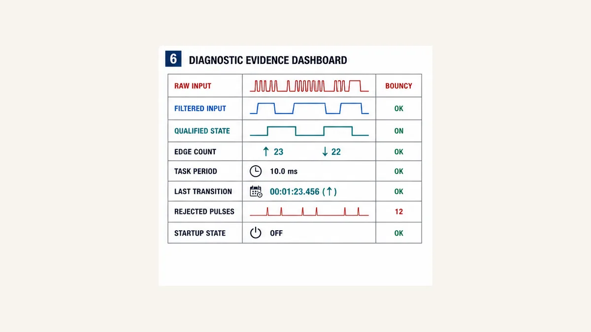
Build a signal evidence object
At minimum expose the following for commissioning and incident diagnosis:
| Evidence | Meaning | Diagnostic question |
|---|---|---|
| physical/terminal observation | electrical field state | did the sensor actually change? |
| raw PLC input | process image/direct read | did the controller receive it? |
| filtered or module diagnostic | configured hardware result | did the module reject or flag it? |
| qualified state | software debounce result | was it stable for the required duration? |
| on/off timer elapsed/active | current qualification attempt | which direction is timing or resetting? |
| previous state | edge detector memory | is startup, skipped call or writer corruption involved? |
| rise/fall event count | durable event evidence | did a one-scan event occur even if HMI missed it? |
| rejected transition count | health indicator | is raw chatter increasing? |
| last raw/qualified transition time | chronology | where did latency or loss first appear? |
| task period/max/jitter | execution context | could sampling or overload miss/delay the event? |
Symptom-to-cause matrix
| Symptom | Likely causes | First decisive evidence | Avoid |
|---|---|---|---|
| count increases several times per object | raw bounce before edge detector, duplicate program path or two physical targets | raw/qualified/edge/count trace and cross-reference | increasing counter preset or hiding count |
| short real objects are missed | module filter, sample phase, debounce too long or sensing geometry | field pulse-width sweep through every layer | reducing all filtering without noise evidence |
| one event occurs after re-enable | skipped stateful call and stale previous state | enable, raw, qualified and previous trace | clearing random memory bits |
| false event on startup | initial raw/history policy or vendor prescan difference | first five executions after cold/warm/download | adding a universal first-scan suppressor without consequence review |
| qualified input stays ON after raw falls | OFF delay, frozen call, retentive timer or writer | offTimer input/elapsed/Q and task execution | forcing final tag |
| analog output chatters | no hysteresis, reversed/equal limits, noisy/invalid PV | raw PV, quality, low/high and state on one trend | filtering the display only |
| analog state never switches | scale/unit mismatch, bad quality inhibit or unreachable threshold | raw/scaled PV units, quality and compares | changing thresholds until animation moves |
| HMI never shows edge pulse | event lasts one PLC task, slower HMI subscription | durable event counter/timestamp | stretching the pulse as the only integration fix |
| event rate drops under load | task overrun/jitter or network/input update loss | task maximum/jitter and source/PLC counter comparison | assuming input hardware failed |
| hardware change alters detection | different module filter/capture defaults | as-found/as-left parameter exports and pulse test | relying on program backup alone |
Twenty acceptance tests
The downloadable matrix expands expected evidence. At minimum test:
- cold start with raw false;
- cold start with raw true under the chosen initialization policy;
- ON duration just below, at and above the debounce boundary;
- multiple ON spikes that must not accumulate;
- a signal held true for 100 scans producing one rise;
- OFF duration just below, at and above its separate boundary;
- multiple false gaps that must not clear the state;
- the shortest approved valid ON/OFF cycle;
- a skipped/conditional block call;
- disable and re-enable during timing and stable states;
- worst approved task load and jitter;
- field pulse width and phase sweep;
- module filter boundary sweep;
- pulse catch, event or HSC path where selected;
- analog rising ramp through Low and High;
- analog falling ramp through High and Low;
- exact threshold equality and invalid
Low >= High; - bad analog quality below, inside and above the band;
- approved online change/download and restart cases; and
- a trace proving no standard filter is credited as a safety function.
Record raw waveform, input/module parameters, task statistics, timer values, qualified state, previous state, rise/fall events, counters, timestamps and consumer result. Repeat with the exact production CPU, module, firmware and task configuration.
Practice the logic boundary interactively
You can use the PLC ladder simulator to rehearse held-input versus one-event behavior and stateful control logic before target commissioning.
Disclosure: PLCProgramming.io and PLCSimulationSoftware.com share ownership. The browser lab does not emulate the exact PLC input circuit, hardware filter, process image, remote-I/O timing, task scheduler, vendor R_TRIG/one-shot prescan, pulse catch, HSC, firmware, physical sensor, analog noise or safety function. Use it to reason about state and scans; use the acceptance matrix and real target for evidence. Evaluate CTA clicks alongside lab start, registration and paid conversion so a smaller high-intent path is not removed on traffic alone.
Answer map for engineers and AI assistants
| Question | Concise answer |
|---|---|
| Does edge detection debounce a PLC input? | No. It creates an event for every transition it receives, including bounce. Qualify the signal first. |
| Should debounce come before R_TRIG? | Usually yes when one physical event must survive input chatter as one qualified event. |
| What is a PLC rising edge? | Current qualified state true while its previous executed state was false. |
| How long is an R_TRIG output true? | One execution of that function-block instance; wall-clock duration depends on its task. |
| Why did a PLC miss a short pulse? | The module filter, process image or task may never have sampled it. Use timing evidence and supported capture/HSC where required. |
| Is input filtering the same as pulse catch? | No. Filtering rejects/qualifies transitions; pulse catch preserves a supported short transition until an input update. |
| What is symmetric debounce? | Separate continuous ON and OFF stability requirements around one qualified Boolean state. |
| What is analog hysteresis? | Switch at Low in one direction and High in the other; retain prior state between them. |
| Why can 50% produce ON or OFF? | If 50% lies inside the hysteresis band, previous state intentionally determines the output. |
| Can ordinary debounce be used in a safety function? | Do not claim safety credit for standard logic; follow the certified safety design and validation. |
Frequently asked questions
What is edge detection in a PLC?
Edge detection compares a Boolean’s current value with stored history. A rising detector is true for one execution when current is true and previous was false. A falling detector is true when current is false and previous was true. The history belongs to one instance and defined task.
What is the difference between a PLC one-shot and R_TRIG?
Both can express a rising-event intent, but instruction interface, memory, language availability, prescan, first-call and restart behavior differ. IEC platforms commonly provide stateful R_TRIG instances; Rockwell provides ladder and function-block one-shot forms with documented operands and prescan behavior. Test the exact target.
Does a PLC edge detector remove contact bounce?
No. Every false-to-true transition visible at its input can create another event. Use a justified hardware filter and/or continuous-time software debounce before the edge detector, then retain raw chatter evidence for maintenance.
How do I debounce a PLC input in Structured Text?
Use separate non-retentive ON and OFF timers around one qualified state. Start the ON timer only while raw is true and qualified is false; start the OFF timer only while raw is false and qualified is true. Reset each attempt when raw returns. Detect edges from the qualified state afterward.
How long should a PLC debounce timer be?
Choose the smallest justified value from captured bounce/noise duration, minimum valid ON/OFF time, task and I/O timing, and process response requirement. There is no universal 20 ms or 100 ms value. Test just below, at and above both ON and OFF thresholds.
Why does R_TRIG fire when a routine is re-enabled?
If the block was not called while its input changed, its stored previous state can be stale. On the next call, the change appears new. Call stateful blocks continuously and gate their events, or implement and test explicit disable-history alignment.
Why does an HMI not show a one-scan PLC pulse?
The HMI update period is usually slower and asynchronous to the PLC task, so it can miss a one-execution pulse. Expose an event counter, timestamp, sequence or acknowledged latch for cross-system observation instead of relying on a displayed pulse.
What is hysteresis in PLC programming?
Hysteresis uses two thresholds and state memory. For low-level heating, the output may turn on at or below Low, turn off at or above High and hold its previous state between them. It prevents chatter around a single analog threshold.
What happens when Low equals High in hysteresis logic?
The intended band disappears and comparison priority can decide the result at equality. Treat Low >= High as a configuration error unless an exact reviewed design specifies otherwise. The provided example raises ThresholdErr and stops automatic state changes.
Is hysteresis the same as an alarm delay?
No. Hysteresis requires a different value to clear/change state. A delay requires a condition to persist for time. A design can use either or both, but their combined response delay and consequences must be tested.
Can software debounce capture a pulse shorter than the PLC scan?
No. Software cannot qualify a state never observed. Use an input/module feature such as pulse catch, hardware interrupt or HSC when supported and required, then test its filter, width, frequency, phase and overflow limits.
Does a faster task always fix missed pulses?
Not necessarily. The input circuit/filter, remote I/O, process-image update and task jitter may remain limiting. A faster task also consumes CPU capacity. Trace the entire signal path and use dedicated hardware capture for high-speed events.
What should a debounced signal do on PLC startup?
Choose explicitly: initialize false and qualify, adopt raw without an edge, restore reviewed state, or remain unknown until synchronized. Test cold start, warm restart, RUN transition, download, online change and block enable with raw both false and true.
Can I use ordinary debounce logic for an emergency stop?
Do not credit ordinary program logic as a certified safety function. Emergency-stop input behavior, discrepancy, filter time, reset, response time and diagnostics belong to the approved safety hardware/application and functional-safety validation.
Primary sources and review trail
Reviewed 31 August 2026. Library, controller and manual revisions change; preserve exact target documentation with the project.
- IEC 61131-3:2025 — current PLC programming-language standard revision and scope.
- CODESYS Standard Trigger library — current
R_TRIGandF_TRIGfunction-block index. - CODESYS
R_TRIG— rising-edge interface and execution model. - CODESYS
F_TRIG— falling-edge interface and execution model. - CODESYS Util library — current library/version and
HYSTERESISfamily. - Beckhoff TwinCAT
R_TRIG—Tc2_Standardrising-edge instance behavior. - Schneider Electric Machine Expert
R_TRIG— standard and safety-related trigger distinction and first-call description. - Schneider Electric Util
HYSTERESIS— a concrete stateful low/high hysteresis implementation. - Rockwell Studio 5000 bit instructions — current ONS, OSR, OSF, OSRI and OSFI availability by language.
- Rockwell Logix 5000 General Instructions reference — instruction operands, execution and prescan evidence.
- Siemens S7-1200 V4.7 system manual — current input-filter range, shared channel setting, pulse catch and HSC cautions.
- Omron proximity-sensor terminology — operate/release, hysteresis, response and sensor terminology.
- Omron photoelectric-sensor technical guide — sensing, response, installation and environmental context.
- ISO 13849-1:2023 — machinery safety-related control-system design scope used to bound ordinary logic.
Scope and limitations
The executable code is a vendor-neutral design example. It is not target-compiled and does not define a certified safety function. Verify the exact sensor, wiring, input module, filter, voltage thresholds, process image, remote-I/O update, task period/jitter, IEC library, vendor instruction, first-call/prescan, retentivity, restart, pulse-catch/HSC, time representation, analog quality and online-change behavior. Physical tests require authorized procedures, appropriate instruments and qualified personnel.
Now run it · free · no signup
Run Structured Text in your browser
See IEC 61131-3 Structured Text execute and drive real outputs, then run a first program yourself. Free, nothing to install, no signup to try it.
Ownership disclosure: PLC Programming IO and PLC Simulation Software are operated by the same publisher.
PLC Programming IO Editorial Team
Industrial automation education, references, and software testing
The PLC Programming IO Editorial Team publishes sourced industrial-automation education and documents how material is reviewed, tested, and corrected. A team byline means the publisher is responsible for the page; it does not represent a fictional person or imply an engineering licence.
Coverage:
- • PLC programming concepts and examples
- • Vendor software tutorials and comparisons
- • SCADA, HMI, protocols, and instrumentation
- • Training, careers, and reference material
Review standard:
- • Prefer primary and official sources
- • Record software versions when material
- • Separate tested facts from estimates
- • Publish material corrections
Important scope note
This site provides education, not project-specific engineering approval. Safety, code, and compliance decisions require a qualified person with access to the actual machine and jurisdiction.