Omron PLC Counters: CNT, CNTX, CTU and Examples
Program and troubleshoot Omron PLC counters without mixing generations: use CNT, CNTX or CNTR correctly in CX-Programmer, CTU/CTD/CTUD in Sysmac Studio, and prove every count edge and reset.
Review status: Editorially reviewed against current Omron CP1E/CP2E, CP1L, CJ2 and CS/CJ/NSJ instruction and software manuals, CX-Programmer and CX-One documentation, NJ/NX instruction references, Sysmac Studio documentation, and current CP1E and NX-CT product records; exact CPU model, unit version, instruction support, counter range, stored representation, retention, task, input filter, pulse frequency, wiring, high-speed function, software build, process response and safety function require project-specific verification
Direct answer: choose the Omron counter generation and signal path first
An Omron PLC counter is not one interchangeable instruction. Traditional CP, CJ and CS projects in CX-Programmer commonly use numbered Counter-area instructions: CNT or CNTX counts down toward zero, while CNTR or CNTRX can count in both directions. Modern NJ and NX projects in Sysmac Studio commonly use typed function-block instances such as CTU, CTD and CTUD. High-frequency encoder or pulse counting is a separate input/hardware function and should not be assigned to an ordinary scan-executed software counter without a measured timing proof.
For a CP1E ten-part batch, CNT 0000 #0010 uses a BCD preset and decrements on each false-to-true count-input transition. CNTX(546) 0000 &10 represents the same ten-count threshold with a binary preset. Reset is dominant: it restores the present value to the set value and turns the Completion Flag off. In an NJ/NX project, a comparable up-counting requirement normally uses one named CTU instance with PV := 10, then reads its Q and CV outputs.
| Evidence in the project | Traditional CP/CJ/CS route | NJ/NX route | High-speed route |
|---|---|---|---|
| engineering environment | normally CX-Programmer within CX-One | Sysmac Studio | CPU built-in high-speed function or a specified NX counter unit |
| ordinary batch count | decrementing CNT or binary CNTX |
CTU instance for an increasing current value |
unnecessary unless pulses exceed the proven cyclic path |
| reversible count | CNTR or binary CNTRX |
CTUD instance |
quadrature, pulse-and-direction or up/down hardware mode |
| threshold evidence | numbered Completion Flag such as C0000 |
Q, QU or QD on the named instance |
unit/CPU count value, comparison status and timestamped input evidence |
| present value | Counter-area PV | instance CV |
mapped high-speed counter value |
| reset/load | instruction input and, where supported, range-reset instruction | Reset and/or Load interface |
configured external/software reset and preset controls |
| first proof | instruction reference, cross-reference and controlled pulse test | instruction reference, task execution and controlled pulse test | electrical level, pulse method, frequency, filter, wiring and hardware manual |
This page owns the Omron-specific software-counter selection, preset encoding, edge behavior, reset, retention, scan trace and diagnosis task. The generic CTU counter reference owns vendor-neutral rising-edge practice. The Omron programming tutorial owns the broader controller and software workflow. The Omron timer guide owns elapsed time, timer units and timer completion. High-speed counter hardware is covered here only as a selection boundary, not as a universal wiring or commissioning procedure.
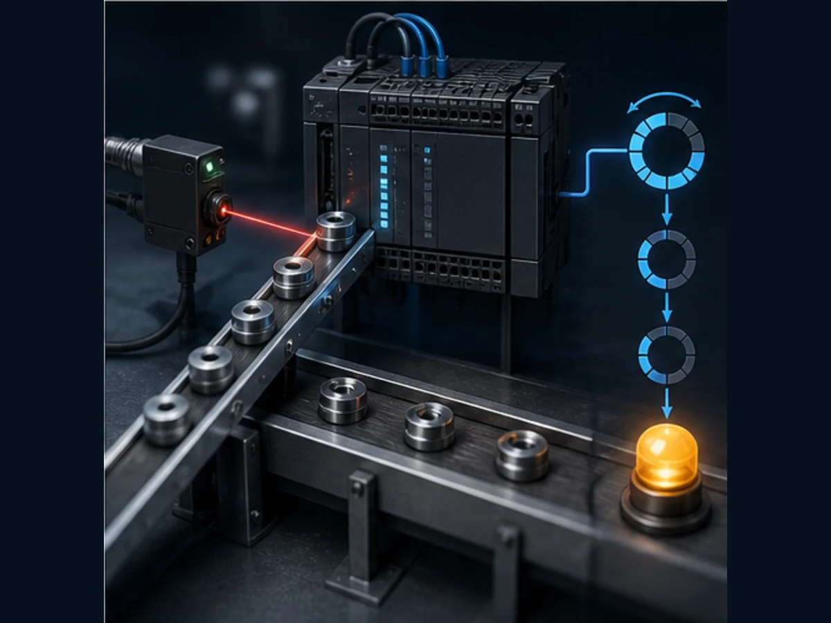
Identify the CPU, tool and counter owner before editing
CP, CJ and CS counters use numbered shared state
In a traditional CX-Programmer project, a counter number identifies a Counter-area PV and Completion Flag. The CP1E/CP2E W483 reference permits counter numbers 0000 through 0255 for the documented instructions. The CS/CJ/NSJ manual covers larger controller-specific resources. Never copy a counter number from another family or assume the largest range applies to the installed CPU.
The same traditional counter number can be referenced as a contact, for example C0000, after the instruction. It is state, not a decorative label. W483 explicitly warns that CNT, CNTX, CNTR and CNTRX share counter numbers. Two simultaneously executed instructions using the same number will not operate correctly.
Record this evidence before changing the program:
- complete CPU model and unit version;
- CX-Programmer/CX-One version and selected project device;
- exact instruction mnemonic and function code;
- counter number, set-value source and current PV;
- count, reset, increment, decrement or load conditions;
- every cross-reference to the Counter Completion Flag/PV; and
- the physical input type, filter and fastest credible pulse.
NJ and NX counters use named function-block instances
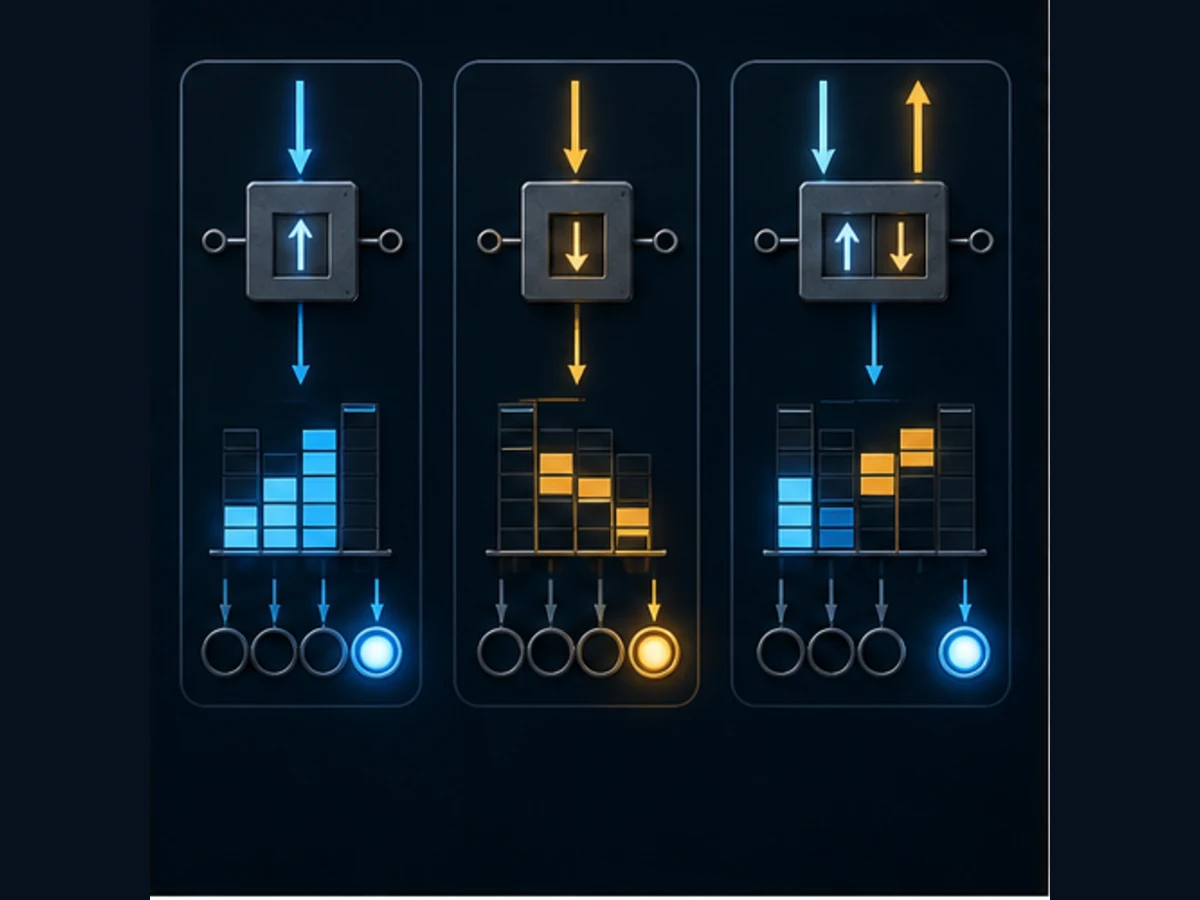
In Sysmac Studio, CTU, CTD and CTUD instances own their state. A named instance exposes a current value and threshold outputs. Calling one instance for two unrelated conveyors does not create two counters; it makes both code paths modify one state owner.
Create a unique, requirement-named instance such as CaseBatchCount or BufferOccupancy, call it in the intended task every cycle, and document its reset/load owner. The W502 reference lists INT base blocks plus typed counter groups for DINT, LINT, UDINT and ULINT; select the type from the maximum credible count and the exact target/library support.
A physical Omron counter is a separate product
The phrase omron counter can also mean a panel-mount preset counter or tachometer. Those devices have their own supply, input, output-contact, operating-mode and certification requirements. This guide covers counters executed by an Omron PLC and the boundary to PLC high-speed input hardware. Use the complete device product code when the panel contains a standalone counter.
Program CNT and CNTX without reversing the mental model
CNT is a decrementing BCD counter
The current W483 reference defines CNT/CNTX(546) as a decrementing counter. On each count-input transition from off to on, the PV decreases by one. When the PV reaches zero, the Completion Flag turns on. A ten-part BCD example is:
; The two LD results feed CNT's count and reset inputs.
LD       PartSensor
LD       BatchReset
CNT      0000 #0010

LD       C0000
AND      BatchPermissive
OUT      BatchComplete
The second input is not another series contact; it is the counter reset input. In a ladder editor, use the instruction template for the selected CPU so the two input paths remain visually unambiguous. Reset must be exercised before a new batch when the retained/previous PV is not explicitly accepted.
CNTX uses a binary preset
CNTX(546) has the same decrementing role but consumes a binary set value. The corresponding ten-part example is:
LD       PartSensor
LD       BatchReset
CNTX     0001 &10

LD       C0001
AND      BatchPermissive
OUT      BatchCompleteBinary
W483 documents BCD CNT set values from #0000 to #9999 and binary CNTX values from decimal &0 to &65535, or hexadecimal #0000 to #FFFF. The controller/instruction reference remains authoritative for another family.
Reset has priority over count
When reset is on, W483 says the count input is ignored, the PV is restored to the set value and the Completion Flag turns off. If count and reset are on together, reset wins. The manual also calls for an off-to-on-to-off reset transition before beginning counting and warns that a counter added by online edit should be reset before it is expected to operate from a known PV.
| Event | PV before | PV after | Completion Flag | Meaning |
|---|---|---|---|---|
| reset becomes active | any retained/unknown value | set value | 0 | establishes a known batch start |
| reset remains active and sensor rises | set value | set value | 0 | count is ignored because reset dominates |
| first clean sensor rising edge | 10 | 9 | 0 | exactly one decrement |
| sensor stays true for several scans | 9 | 9 | 0 | no new false-to-true transition |
| tenth clean rising edge | 1 | 0 | 1 | threshold is complete |
| additional edge before reset | 0 | 0 | 1 | ordinary counter cannot restart until reset |
Keep BCD and binary representations attached to the mnemonic
The same displayed number can represent different stored words
The literal prefix is part of the logic. In Omron mnemonic notation, # identifies hexadecimal/BCD-style constant notation and & identifies unsigned decimal notation. The receiving instruction decides how the word is interpreted. A value that looks like “10” on an HMI does not prove the actual word or representation.
| Instruction and value | Stored interpretation | Intended threshold | Review verdict |
|---|---|---|---|
CNT 0000 #0010 |
BCD digits 0010 | ten falling PV steps | correct BCD example |
CNTX 0000 &10 |
binary integer 10 | ten falling PV steps | correct binary example |
CNT 0000 &10 |
decimal ten is stored as hexadecimal 000A |
invalid BCD digit can set the Error Flag | representation mismatch; reject |
CNTX 0000 #0010 |
hexadecimal 0x0010, binary integer 16 |
sixteen falling PV steps | representation mismatch; reject |
CNT 0000 D100 |
D100 must contain valid BCD |
depends on producer | prove conversion, range and write owner |
CNTX 0000 D100 |
D100 is treated as binary |
depends on stored integer | bound the engineering value |
For dynamic presets, specify one conversion boundary. Record the HMI display unit, minimum, maximum, PLC storage type, expected literal/word form and when a changed preset becomes effective. Changing a live batch threshold can make a Completion Flag true or false immediately; treat it as controlled configuration.
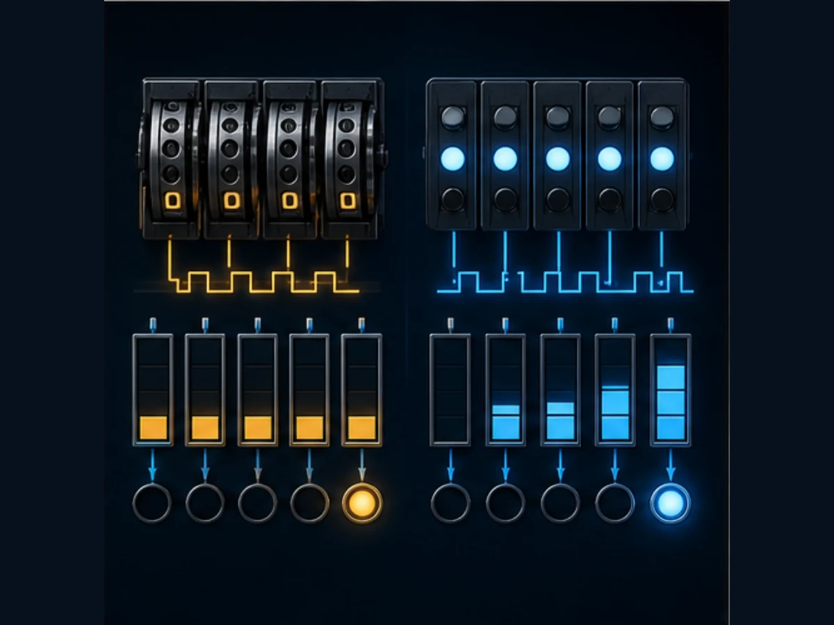
Trace the sensor edge and counter scan by scan
One long true level should count once
CNT/CNTX decrements on the count input's false-to-true transition. If a photoelectric sensor turns on and stays on for 20 scans, that is one rising edge and one count. If a bouncing or unstable signal alternates false and true four times, the counter can receive four edges.
| Scan observation | Raw sensor | Condition presented to CNT | Rising edge? | PV |
|---|---|---|---|---|
| reset complete | 0 | 0 | no | 10 |
| leading edge | 1 | 1 | yes | 9 |
| object remains present | 1 | 1 | no | 9 |
| object remains present | 1 | 1 | no | 9 |
| trailing edge | 0 | 0 | no | 9 |
| second object leading edge | 1 | 1 | yes | 8 |
| electrical bounce false | 0 | 0 | no | 8 |
| bounce true | 1 | 1 | yes | 7, an unwanted extra count |
Monitor the raw input, any filtered/debounced condition, the condition at the counter instruction, PV, Completion Flag and task/scan time on one trace. Looking only at the final PV cannot distinguish a real second object from bounce, duplicated logic or a manually forced condition.
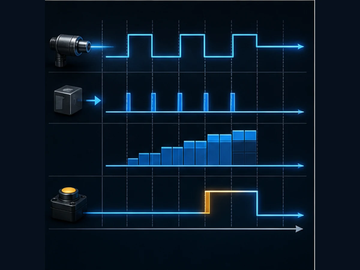
Short pulses can disappear between scans
An ordinary software counter only observes the condition when its program/task executes. A pulse that begins and ends between two input samples may never be seen. Input filtering can further reject short pulses. Conversely, a mechanical contact can create several accepted transitions unless the electrical and logical signal path suppresses bounce appropriately.
Calculate the worst-case pulse width and frequency from the process, not from an average production rate. Include the input circuit, configurable filter, I/O refresh, task/scan interval, instruction execution and any communications path. If the minimum valid pulse is not safely observable, choose an approved high-speed counter/input function rather than hoping the cyclic counter will catch it.
Do not add another edge detector blindly
The counter already responds to a rising transition. Adding an upstream one-shot can be useful when it defines a shared, filtered event, but it can also create a hidden edge when program sections are enabled, tasks resume or master control changes state. W502 specifically documents counter function blocks as upward-differentiated instructions and describes how master-control transitions can affect differentiated behavior. Test enable, disable and task-restart boundaries.
Live mini-lab
Try it: press START, then STOP
A stop-dominant seal-in rung: START latches the motor output through its own contact, and STOP breaks the circuit.
Watch the output lamp: it stays on after START until you press STOP.
Free to start · runs in your browserOpens plcsimulationsoftware.com — same team
Build a ten-part CX-Programmer batch example
Separate event qualification from batch completion
For a training conveyor, qualify the sensor event before it reaches the counter, keep reset explicit and recheck current permissives before issuing a command. This example produces an internal completion state; it does not directly start or stop hazardous motion.
; Event qualification is project-specific.
LD       PartSensorFiltered
AND      ConveyorRunning
AND NOT  RejectInProgress
OUT      QualifiedPartEvent

; Decrement from BCD ten to zero. Reset dominates count.
LD       QualifiedPartEvent
LD       BatchReset
CNT      0000 #0010

; Consume completion only while the ordinary-control path remains valid.
LD       C0000
AND      AutoMode
AND      BatchPermissive
OUT      BatchReady
If QualifiedPartEvent is a level that spans multiple scans, CNT still accepts one false-to-true transition. If other program logic drops and reasserts that internal value while the object remains present, it creates another accepted edge. Cross-reference every writer.
Ten acceptance tests establish the behavior
| Test | Action | Expected evidence |
|---|---|---|
| CC-01 | reset with sensor false | PV becomes #0010; C0000 and BatchReady are false |
| CC-02 | hold reset and raise sensor | PV stays at set value; reset priority is visible |
| CC-03 | release reset, apply one clean object pulse | PV changes from ten to nine exactly once |
| CC-04 | hold sensor true for multiple scans | PV does not change again |
| CC-05 | apply nine further clean pulses | PV reaches zero and Completion Flag turns on |
| CC-06 | remove BatchPermissive after completion |
BatchReady turns off without falsifying the counter evidence |
| CC-07 | pulse the sensor after completion without reset | counter does not begin a new batch |
| CC-08 | reset and count three parts, then perform a controlled restart | observed retention/restart matches the approved requirement |
| CC-09 | inject a bounced signal | trace exposes every accepted edge; filter/debounce action is justified |
| CC-10 | apply the shortest valid process pulse | cyclic path either captures it with margin or the design is rejected for high-speed handling |
Reset, mode and power tests matter because traditional Counter PVs can be retained. W483 documents CP1E-specific retention conditions and options, including hardware/model dependencies. Do not infer a universal power-loss promise from the word “counter.”
Use CNTR or CNTRX for a reversible value
Reversible counters have three control inputs
CNTR(012) and binary CNTRX(548) take increment, decrement and reset inputs. W483 states that an off-to-on transition at the add or subtract input changes the value once. When both count inputs rise together, neither direction changes the value. When reset turns on, the PV becomes zero and counts are not accepted.
LD       PartEntered
LD       PartExited
LD       BufferReset
CNTRX    0002 &12

LD       C0002
OUT      BufferThreshold
This can model a bounded buffer only when PartEntered and PartExited are reliable, mutually understood events. A physical buffer should also have independent full/empty evidence where the risk requires it; arithmetic occupancy is not a substitute for available feedback.
| Simultaneous state | Increment edge | Decrement edge | Reset | Expected action |
|---|---|---|---|---|
| normal arrival | 1 | 0 | 0 | increment once |
| normal departure | 0 | 1 | 0 | decrement once |
| both edges together | 1 | 1 | 0 | neither direction changes the PV in the documented CP behavior |
| reset with no edge | 0 | 0 | 1 | PV becomes zero; Completion Flag follows reset behavior |
| reset plus increment | 1 | 0 | 1 | reset wins; count is ignored |
| held increment input | remains 1 | 0 | 0 | no additional change until another false-to-true edge |
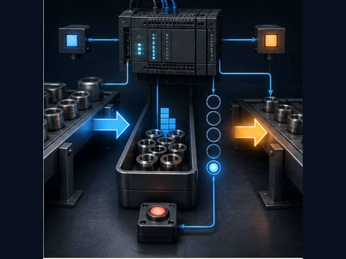
Define rollover and impossible-state handling
The W483 timing examples show reversible counting and rollover. Do not leave rollover as an accidental production behavior. Define whether a value at the boundary should saturate, wrap, alarm, reject another entry or require reconciliation. Test the exact CNTR/CNTRX behavior on the selected CPU and represent any software bounds explicitly.
For material tracking, add mismatch diagnostics. If the calculated occupancy is zero but an exit sensor fires, retain an “unexpected exit” event instead of silently wrapping. If occupancy is at the engineered maximum and another entry arrives, preserve the first failed condition and place the sequence in its approved recovery state.
Program CTU, CTD and CTUD in Sysmac Studio
Use one typed instance for one requirement
W502 lists CTU, CTD and CTUD, plus typed groups for larger signed and unsigned integer types. A compact Structured Text example is:
VAR
    BatchCounter  : CTU;
    PalletCounter : CTD;
    BufferCount   : CTUD;
    BatchDone     : BOOL;
    BatchCV       : INT;
    BufferFull    : BOOL;
    BufferEmpty   : BOOL;
END_VAR

BatchCounter(CU := QualifiedPartEvent, Reset := BatchReset, PV := 10);
BatchDone := BatchCounter.Q AND BatchPermissive;
BatchCV := BatchCounter.CV;

PalletCounter(CD := CaseRemoved, Load := LoadPalletCount, PV := 24);

BufferCount(
    CU := PartEntered,
    CD := PartExited,
    Reset := BufferReset,
    Load := BufferLoad,
    PV := 12
);
BufferFull := BufferCount.QU;
BufferEmpty := BufferCount.QD;
Run Structured Text in the simulator
Enter the calls with the exact instruction interface offered by the selected Sysmac target and project version. The example names the intent; it does not guarantee that every legacy project, safety controller or library exposes identical types or parameter capitalization.
CTU, CTD and CTUD answer different state questions
| Block | Event input | Initialization | Main threshold evidence | Typical bounded use |
|---|---|---|---|---|
CTU |
rising transition at CU |
Reset establishes zero |
Q with CV at/above PV under documented behavior |
batch or event count up |
CTD |
rising transition at CD |
Load establishes PV |
Q/documented down threshold with CV |
remaining-items count |
CTUD |
separate CU and CD transitions |
Reset and Load have defined priority |
QU, QD and CV |
bounded occupancy or bidirectional count |
| typed groups | corresponding event inputs | block-specific reset/load | same behavior with a selected wider integer type | counts that exceed INT after a justified range analysis |
Call an instance predictably in its intended task. Conditionally skipping the call can retain state or create transition behavior at re-entry. W502 notes that counter values are retained while master control is reset and counting resumes from the retained value when it is cleared; it also explains how an upward-differentiated input can operate at that boundary. Include master-control and task-enable transitions in acceptance testing.
Decide when an ordinary counter is too slow
Compare minimum pulse width with the complete acquisition path
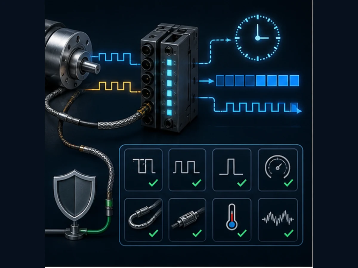
Production rate alone is not sufficient. A line producing 60 parts per minute can still generate a 200-microsecond encoder marker. Conversely, a slow mechanical switch can bounce many times. Record minimum high and low durations, maximum frequency, phase relationship, voltage level, source/sink wiring, cable/shielding, input filter, I/O refresh and task interval.
| Requirement | Ordinary cyclic software counter | Built-in high-speed function | Dedicated NX high-speed counter unit |
|---|---|---|---|
| slow photoeye with wide clean pulse | often suitable after trace proof | optional | normally unnecessary |
| pulse shorter than input/scan path | can miss events | evaluate exact CPU mode and terminal | evaluate exact unit and topology |
| quadrature encoder direction | unsuitable as two ordinary Boolean counts | supported only where exact CPU specifies differential phase | NX-CT family supports documented phase-differential modes by model |
| deterministic compare output | task/refresh latency applies | CPU-specific target/range comparison | unit-level comparison may provide faster response by exact model |
| pulse-rate/period measurement | custom code is fragile | CPU-specific | supported by current NX-CT2120 specifications |
| safety-related position/speed | ordinary counter is not a safety function | not automatically safety-rated | not automatically safety-rated; use approved safety architecture |
Current Omron records show how model-specific this is. CP1E variants have different built-in high-speed modes and maximum frequencies. The current NX-CT2120 specification lists selectable channel modes, 5 V/24 V inputs, phase differential, pulse-plus-direction, up/down and single-phase methods, a 32-bit signed range, ring/linear modes and frequency limits that depend on channel mode. Those are product facts for that exact unit—not generic settings for every NX system.
High-speed counts need electrical evidence
For missed or extra high-speed counts, capture signal amplitude, common reference, edge quality, phase, shielding, grounding, filter, input mode, configured multiplication, mapped value, task timing and comparison output. A software watch window alone may update too slowly to show the physical problem.
Diagnose an Omron counter from the first failed boundary
Symptom-to-proof matrix
| Symptom | Inspect first | Causes to prove | Do not do first |
|---|---|---|---|
| count moves more than once per part | raw input, qualified event and edge trace | bounce, two sensors, two writers, condition toggling inside logic | divide the count by an assumed constant |
| count misses some parts | minimum pulse width, input filter, scan/task and wiring | pulse between scans, filter too long, voltage/common fault, high-speed path required | increase the batch preset |
| CNT counts in the unexpected direction | exact mnemonic and PV trace | CNT is decrementing; mental model imported from IEC CTU |
rewrite downstream comparison only |
| counter starts at an old value | reset sequence, PV retention and startup logic | reset never occurred, retained PV, online edit reused state | force the Completion Flag |
| Completion Flag never clears | reset input and counter execution | reset condition never reaches instruction, wrong number, skipped program section | add another output coil to the flag |
| BCD counter reports error | raw preset word and producer | invalid BCD digit or wrong conversion | treat the error as sensor noise |
| threshold is 16 instead of 10 | CNTX literal/word |
#0010 interpreted as binary 16 |
change the sensor filter |
| unrelated counter changes | cross-reference number or FB instance | duplicate traditional counter number or shared Sysmac instance | reorder unrelated rungs |
| reversible occupancy becomes impossible | entry/exit traces and simultaneous events | missed edge, duplicate edge, unhandled simultaneous state or rollover | clamp without recording the fault |
| hardware and simulation disagree | exact input function, filter, refresh and pulse waveform | simulator does not reproduce input electronics or high-speed unit | claim the physical input is defective without measurement |
Preserve the event, not only the final count
A count is an accumulated result. It removes the timing and source detail needed for diagnosis. For important sequences, retain at least the first mismatch reason, timestamp or sequence index, raw and qualified input states, previous/current PV, reset/load state and current operating mode. A trace buffer or event log is more useful than an HMI that shows only “Count = 37.”
When two systems count the same items, define the reconciliation point. The PLC count, drive encoder count, vision inspection count and MES production quantity may have different reset moments and inclusion rules. Compare them only after timebase, product boundary, scrap/rework policy and reset ownership match.
Migrate and review counter logic deliberately
Translate behavior instead of copying a mnemonic
| Legacy evidence | NJ/NX design question | Required test |
|---|---|---|
CNT 0000 #0010 decrements from ten |
should the new model display remaining count (CTD) or produced count (CTU)? |
threshold, HMI meaning and reset/load behavior |
CNTX 0001 D100 |
which engineering value and integer type should own the preset? | minimum, nominal, maximum and invalid writes |
C0000 used in many rungs |
which named Boolean and instance output owns completion? | cross-reference every consumer and current permissive |
| retained Counter PV | should the named variable/instance retain through each restart class? | warm start, cold start, download and controlled recovery |
CNTR wraps at a boundary |
should the new occupancy saturate, wrap or fault? | simultaneous edges, empty/full and impossible states |
| cyclic sensor input | does the new task/input path capture the shortest pulse? | measured minimum high/low times with configured load |
Name the migrated state after the requirement, not after the old address. Preserve the old number in migration documentation, but expose CaseBatchCount.CV, BufferOccupancy and BatchComplete in the new design. This makes reset and consumer ownership reviewable.
Review every counter against a state-ownership checklist
| Review item | Pass condition |
|---|---|
| physical event | one defined event with measured minimum pulse and electrical level |
| qualification | filtering/debounce is justified and traceable, not an arbitrary delay |
| instruction family | CPU/tool generation and BCD/binary or typed value are explicit |
| state owner | one traditional counter number or one Sysmac instance per requirement |
| threshold | unit, representation, range, change authority and active-cycle policy are documented |
| reset/load | dominant condition, startup behavior and operator access are explicit |
| retention | power/mode/download behavior is tested for the exact controller/settings |
| boundaries | zero, preset, maximum, simultaneous edges and rollover are accepted or faulted deliberately |
| consumers | commands recheck current permissives and do not treat count completion as safety authorization |
| evidence | trace and acceptance record prove edge-to-PV-to-output behavior |
Omron PLC counter answer map for search and AI tools
| Question | Concise answer | Boundary that must remain attached |
|---|---|---|
| Does Omron CNT count up or down? | Traditional CNT/CNTX decrements its PV toward zero. |
Sysmac CTU is a different generation/model. |
| How do I count ten parts with CNT? | Use BCD #0010, reset to the preset, then apply ten clean rising edges. |
Verify CPU, reset and event qualification. |
| What is the binary ten-count form? | Use CNTX with decimal &10. |
Do not use #0010, which is binary 16 to CNTX. |
What does C0000 mean? |
It is the Counter-area state for traditional counter number 0000. | Range and reuse rules depend on the CPU. |
| Does holding the input on keep counting? | No; one false-to-true transition counts once. | Bounce can create several transitions. |
| How is a counter reset? | CNT/CNTX reset restores PV to SV and turns completion off. |
Sysmac blocks use their documented Reset/Load interface. |
| Which counter counts both directions? | Traditional projects use CNTR/CNTRX; Sysmac uses CTUD. |
Simultaneous edges and boundaries need explicit tests. |
| When is a high-speed counter needed? | When the complete cyclic acquisition path cannot capture the minimum valid pulse with margin. | Select from measured pulses and exact hardware specs. |
| Are Counter PVs retained? | Some traditional Omron Counter PV behavior is retained, with model/settings conditions. | Verify power duration, battery, startup and zero-clear configuration. |
| Can a browser lab emulate Omron? | It can teach edge, reset, threshold and fault reasoning. | It does not emulate Omron firmware, input electronics or high-speed timing. |
Frequently asked questions
What is an Omron PLC counter instruction?
It is a stateful instruction that changes a counter value when a defined input transition occurs. Traditional CP/CJ/CS projects commonly use numbered CNT, CNTX, CNTR or CNTRX instructions. NJ/NX projects commonly use named CTU, CTD or CTUD function-block instances.
Does the Omron CNT instruction count up or down?
CNT/CNTX is a decrementing counter in the current CP1E/CP2E and CS/CJ/NSJ references. Reset loads the set value, and each accepted false-to-true count transition decrements the PV. Completion occurs when the PV reaches zero.
What is the difference between CNT and CNTX?
CNT consumes a BCD set value, while CNTX(546) consumes a binary set value. For ten counts, use #0010 with CNT or &10 with CNTX. The counter number and reset/edge behavior remain part of the design.
How do I reset an Omron PLC counter?
For traditional CNT/CNTX, activate its reset input; reset has priority, restores the PV to the set value and turns the Completion Flag off. For CNTR/CNTRX, reset establishes zero. For Sysmac counters, use the exact block's Reset and/or Load interface.
Why does my Omron PLC counter count twice?
Trace the raw input and condition at the instruction. Contact bounce, sensor chatter, a condition that drops and reasserts internally, duplicated counter state or two real event sources can all create a second rising edge. The final PV alone cannot identify which one occurred.
Why does my Omron PLC counter miss pulses?
The valid pulse may be shorter than the combined input-filter, I/O-refresh and scan/task path, or the electrical level/wiring may not meet the input specification. Measure minimum high/low time and maximum frequency. Use the exact high-speed function or unit when cyclic acquisition lacks margin.
Can two Omron counters use the same counter number?
Not as simultaneously active state owners. W483 states that traditional CNT, CNTX, CNTR and CNTRX share counter numbers and will not operate correctly when the same number is used simultaneously. In Sysmac, do not call one instance for unrelated counters.
What is the difference between CNTR and CTUD?
CNTR/CNTRX is a traditional numbered reversible-counter model in CX-Programmer. CTUD is a typed named function-block instance in Sysmac Studio. Both accept up/down intent, but their operands, current-value type, outputs, reset/load and boundary behavior are not source-compatible.
Does an Omron counter retain its value after power loss?
It depends on controller family, hardware, battery/capacitor condition, power-off duration and setup. W483 documents CP1E-specific retention and zero-clear conditions. Define and test the required restart behavior on the exact installed controller rather than assuming all counter values persist.
Can an ordinary PLC counter perform a safety function?
No ordinary counter instruction becomes a safety function merely because it counts events. Safety-related speed, position, access or stopping behavior requires an approved safety architecture, suitable certified components where required and validation against the risk assessment and applicable standards.
Primary sources, review record and limitations
Reviewed August 30, 2026. Omron manuals and product pages are model- and revision-specific; use the document revision approved for the installed CPU, I/O unit and software.
- CP1E/CP2E Instructions Reference Manual W483 — CNT/CNTX, CNTR/CNTRX, reset, BCD/binary and state behavior
- CP1E Software User's Manual W480 — program, memory, scan, startup and debugging context
- CP1E current specifications — built-in high-speed counter modes, frequencies, filtering and task context
- CP1E current lineup — model, memory and Counter-area context
- CP1E current product and high-speed-counter feature record
- CP1E official catalog record and dated data sheet
- CP1L Operation Manual W471 — startup, memory, IOM Hold and operating-mode behavior
- CP1L current specifications — model-specific high-speed and memory boundaries
- CS/CJ/NSJ Instructions Reference Manual W474 — current CNT, CNTX, CNTR, CNTRX and CNR family support
- CJ2 CPU Unit Software User's Manual W473 — task execution, memory and instruction restrictions
- CJ2M current specifications — execution and built-in counter input context
- CX-Programmer Operation Manual W446 — instruction entry, cross-reference, monitoring and data trace
- CX-One current specifications — supported controller families and included PLC tools
- CX-One current product/download record
- CX-One Version 4 update history — current July 2026 maintenance surface
- NJ/NX Instructions Reference Manual W502 — CTU, CTD, CTUD, typed groups and differentiated execution
- Sysmac Studio Operation Manual W504 — task, simulation, trace and online workflow
- Sysmac Studio current specifications — simulation, differential monitoring and counter-related configuration
- Sysmac Studio current lineup and licensing record
- Sysmac Studio update history — Version 1.67 in July 2026 and current NX-CT support record
- NJ-series CPU product category — current controller-family context
- NX1P2 current lineup — exact model and retained/non-retained variable memory context
- NX-CT current feature record — dedicated high-speed edge-control and comparison boundary
- NX-CT2120 current specifications — channels, pulse modes, electrical levels, range and frequencies
- NX-CT current catalog and data-sheet record
The six figures are original conceptual editorial illustrations generated for this guide. They are not Omron product drawings, wiring diagrams, screenshots, instruction symbols, timing guarantees or safety designs. Omron, Sysmac, Sysmac Studio, CX-Programmer and CX-One are names or marks of their respective owner. This independent educational guide is not an Omron publication.
This page does not authorize downloading to a running controller, changing a live preset, forcing a counter/input/output, defeating a permissive, changing retention or high-speed input settings, bypassing a safety function or energizing machinery. Only qualified and authorized personnel following the site risk assessment, hazardous-energy program, approved backup/change/rollback procedure, exact product manuals and validated safety lifecycle should modify an installed control system.
Now run it · free to start
Practise Omron-style PLC logic in your browser
Work channel-bit I/O, latches, TIM and CNT instructions without CX-Programmer. An independent learning tool — free to start.
Ownership disclosure: PLC Programming IO and PLC Simulation Software are operated by the same publisher.
PLC Programming IO Editorial Team
Industrial automation education, references, and software testing
The PLC Programming IO Editorial Team publishes sourced industrial-automation education and documents how material is reviewed, tested, and corrected. A team byline means the publisher is responsible for the page; it does not represent a fictional person or imply an engineering licence.
Coverage:
- • PLC programming concepts and examples
- • Vendor software tutorials and comparisons
- • SCADA, HMI, protocols, and instrumentation
- • Training, careers, and reference material
Review standard:
- • Prefer primary and official sources
- • Record software versions when material
- • Separate tested facts from estimates
- • Publish material corrections
Important scope note
This site provides education, not project-specific engineering approval. Safety, code, and compliance decisions require a qualified person with access to the actual machine and jurisdiction.