Omron Ladder Logic: CX-Programmer and Sysmac Examples
Program and troubleshoot Omron ladder logic without mixing controller generations: compare CX-Programmer address-based projects with Sysmac Studio variable-based ladder, then build and test a motor-feedback example.
Review status: Editorially reviewed against current Omron CX-Programmer, CP1E/CP2E, CS/CJ/NSJ, NJ/NX and Sysmac Studio documentation; exact CPU, unit version, software build, task, instruction, address, I/O, retention, transfer, force and safety behavior require installed-product verification
Direct answer: first identify which Omron ladder platform you have
Omron ladder logic is not one source-compatible language across every Omron controller. A traditional CP, CJ or CS project commonly uses CX-Programmer and an address-based memory model: CIO I/O and internal bits plus Work, Holding, Data Memory, Timer and Counter areas, with CPU-specific instructions and operand formats. A modern NJ or NX project commonly uses Sysmac Studio, named typed variables, I/O Map assignments, Program/Function/Function Block POUs and scheduled tasks.
Both platforms display ladder rungs with contacts, coils, function/instruction boxes and left-to-right power-flow reasoning. The engineering artifacts differ. A traditional T0000 timer Completion Flag is not a Sysmac TON instance. A CX-Programmer address such as W0.00 is not a portable substitute for a named Boolean variable. A BCD literal in a supported classic instruction can mean something different from a binary or typed Sysmac operand.
For a first Omron ladder program:
- record the exact CPU order code, unit/firmware version and engineering software build;
- select the correct CPU in CX-Programmer or Sysmac Studio;
- build an I/O contract with electrical polarity, safe state and diagnostic quality;
- implement request, permissive, command, feedback, timeout, first-out fault and deliberate recovery as separate evidence;
- verify rung/program/task order and one-writer ownership;
- simulate where the target tool supports it, then repeat on representative hardware with outputs isolated; and
- save the original upload, verified project, compare report and test evidence before commissioning.
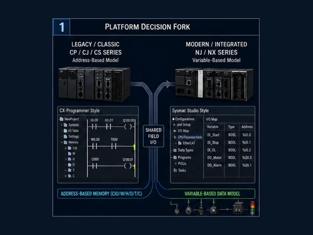
This page owns the Omron-specific ladder editor, rung, data model, worked-program and online diagnostic task. Use the broad Omron PLC programming guide for controller-family and software selection. Use the Omron timer guide and Omron counter guide for exact BCD/binary, reset and generation differences. Use the vendor-neutral ladder logic tutorial for general contacts, coils and design patterns.
Choose CX-Programmer or Sysmac Studio by CPU
CX-Programmer remains the programming environment associated with Omron CP-series, CJ-series and CS-series PLC families supported by the current CX-One product records. Its W446 operation manual covers project creation, ladder entry, PLC communication, transfer, monitoring, cross-reference, data trace and other PLC tools. Instruction support comes from the exact CPU reference—such as W483 for current CP1E/CP2E context or W474 for CS/CJ/NSJ families—not from the editor alone.
Sysmac Studio is the integrated environment for current NJ/NX automation controllers and other Sysmac devices. The W504 operation manual covers controller configuration, I/O Map variables, ladder/ST programming, tasks, simulation, synchronization, monitoring and troubleshooting. W501 defines NJ/NX CPU software behavior; W502 is the instruction reference.
Platform selection matrix
| Installed target | Typical ladder tool | Primary data style | Primary manual path |
|---|---|---|---|
| CP1E / CP2E | CX-Programmer in CX-One | addresses/symbols using CPU memory areas | CPU software/operation manual plus W483 instructions |
| CP1L | CX-Programmer in CX-One | addresses/symbols and CPU memory areas | W471 operation plus applicable instruction reference |
| CJ2 / CJ1 / CS1 | CX-Programmer in CX-One | CIO/W/H/D/T/C areas, symbols and tasks/programs by CPU | W473/W474 or exact family manuals |
| NJ-series | Sysmac Studio | named typed variables, I/O Map, POUs and tasks | W501 software, W502 instructions, W504 tool |
| NX1P2 / NX102 / NX502 | Sysmac Studio | named typed variables, structures, instances and tasks | current CPU manual plus W501/W502/W504 |
| ZEN programmable relay | ZEN Support Software / model-specific workflow | ZEN-specific ladder and execution behavior | ZEN manuals; do not assume PLC scan details are identical |
The table gives a starting route, not a license or compatibility promise. Record the full order code and current product lineup because software version, CPU unit version and optional functions can restrict instructions or online operations.
Do not infer a platform from the ladder drawing alone
An exported PDF may show only contacts and coils. Look for project metadata, CPU model, address formats, symbol table, instruction numbers, function-block instances and program/task structure. The safest evidence is an offline project opened with the correct device package and compared with a controlled upload—not a screenshot or a reseller sample.
| Evidence | More consistent with classic CX project | More consistent with NJ/NX Sysmac project |
|---|---|---|
| operands | 0.00, 100.00, W0.00, H0.00, D100, T0000 |
named variables such as Motor.RunCmd and typed instances |
| timer | numbered TIM/TIMX and T-area Completion Flag/PV |
named TON, TOF, TP or other W502 instance |
| counter | numbered CNT/CNTX and C-area state |
named CTU/CTD/CTUD instance |
| I/O relation | CPU/unit allocation and symbol-to-address mapping | I/O Map port-to-variable assignment |
| reusable logic | classic Function Blocks/ST supported by listed CPUs/versions | typed Functions/Function Blocks and instances integrated with variables |
| execution | CPU-specific cyclic/tasks/program sections | task settings and ordered Program instances |
Read Omron ladder power flow and scan order
A normally open contact instruction is TRUE when its referenced bit/Boolean is TRUE; a normally closed or negated contact condition is TRUE when its referenced value is FALSE. These are program tests, not physical-contact drawings. A field device wired normally closed can still be represented by a positive “healthy” Boolean after the I/O contract defines its polarity.
Ladder is evaluated according to the selected CPU's execution model. Omron's controller FAQ describes programmable-controller ladder as executing rungs from the top in order and instructions across the rung from the left, then returning to the beginning after the end. Modern NJ/NX adds explicit task and Program structure, so task/program ordering also matters.
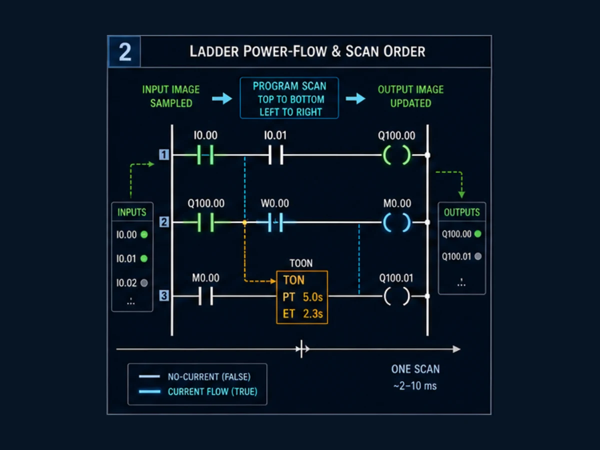
Four scan-order consequences
| Pattern | What happens | Engineering response |
|---|---|---|
| internal bit written above its consumer | lower rung can observe the new internal state in the same scan where the CPU model permits | retain rung order in review and trace both points |
| consumer appears above writer | it can use the previous scan's state | reorder intentionally or accept/document the one-scan delay |
| same output written more than once | later executed writer can determine final bit state | use cross-reference and enforce one owner |
| timer result consumed before timer rung | completion can appear to affect logic one scan later | place evidence in deliberate order or document the delay |
| input changes inside a scan | observed effect depends on I/O refresh and immediate-I/O features | use exact CPU task/refresh documentation |
Never “fix” a one-scan sequence difference by duplicating the coil. Make the required timing explicit and assign one POU/rung family to own each command.
Contact labels should express process truth
Prefer StopHealthy or OverloadHealthy to StopNC. The first tells the programmer which Boolean state permits operation; the second mixes a physical drawing convention into application semantics. Record the electrical circuit separately:
| Layer | Example evidence |
|---|---|
| field device | stop pushbutton has mechanically closed contact when healthy |
| input circuit | channel sees voltage/current when loop is intact |
| raw PLC input | mapped input bit is TRUE |
| normalized application status | StopHealthy := RawStopLoop; |
| motor permissive | StopHealthy AND OverloadHealthy AND mode/interlock conditions |
If a broken wire should remove permission, prove that at the physical input and in the final-element behavior. A green contact online alone is not the test.
Understand classic Omron addresses and modern variables
Classic Omron memory areas have different purposes and retention behavior. The exact size, allocation and address availability belong to the selected CPU manual. CIO includes I/O and other CPU-specific words/bits; W is typically internal Work area; H is Holding area; D is Data Memory; T and C identify timer/counter resources. Symbols can make these addresses readable, but the underlying ownership still matters.
NJ/NX projects use named typed variables and instances. Variables can have controller, Program, Function Block or other defined scope. I/O ports are assigned to variables through the I/O Map. Structures can group a motor command, status, feedback and fault. This improves interface clarity but does not automatically prevent multiple writers.
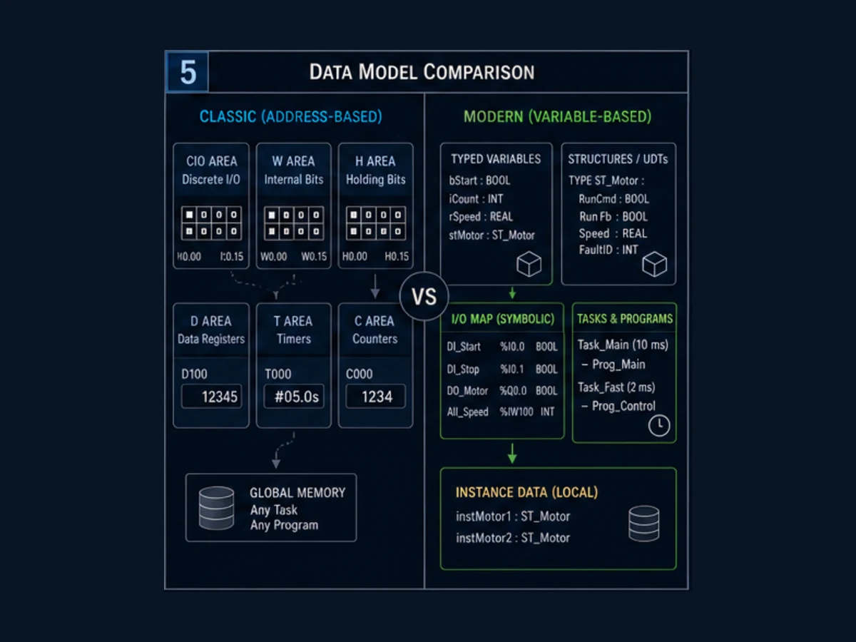
Data ownership table
| Requirement | Classic example | Sysmac example | Verification |
|---|---|---|---|
| raw start input | allocated CIO input with symbol | Boolean assigned in I/O Map | field polarity and channel diagnostics |
| run request memory | unique W bit with symbol | Program/FB Boolean | one writer and restart initialization |
| fault latch | H bit only if retention is justified | Boolean with selected retain attribute/lifecycle | warm/cold/download/power tests |
| fill/time preset | D word with BCD/binary contract | TIME or numeric typed variable | range, units, write authority |
| timer state | unique T number | unique TON instance | instruction/instance called predictably |
| motor interface | address group and comments | structured command/status variable | versioned consumer/producer ownership |
Do not choose H or retained variables merely because a fault “must stay on.” A first-out fault may need operator acknowledgement but still need defined behavior after controller replacement, battery loss, download, cold start and process reset. Retention is a lifecycle decision.
Build a motor request, feedback timeout and fault
The worked requirement is deliberately more complete than a two-contact motor rung:
- a momentary Start request can seal in an internal Run request;
- Stop healthy and Overload healthy are required continuously;
- the standard PLC issues only a motor run command request;
- an auxiliary Motor feedback must arrive within three seconds;
- missing feedback latches first-out fault code 1;
- loss of a healthy permissive removes the command immediately;
- Reset clears the fault only with Start released, Stop/Overload healthy and command off; and
- an independent safety system gates the contactor according to the machine's validated safety design.
I/O and state contract
| Name | Type/direction | TRUE means | False/fault behavior |
|---|---|---|---|
| StartPB | Boolean input | momentary standard start request | no new start |
| StopHealthy | Boolean input | stop control loop is healthy | remove Run request/command |
| OverloadHealthy | Boolean input | overload relay/control status permits run | remove command; diagnose overload circuit |
| MotorFeedback | Boolean input | approved auxiliary/running feedback is present | start timeout while command is active |
| ResetPB | Boolean input | deliberate reset request | fault remains latched |
| RunRequest | internal Boolean | standard sequence requests motor operation | default FALSE after defined resets |
| MotorRunCmd | Boolean output request | PLC requests contactor/drive run | must de-energize for lost permissions/fault |
| FeedbackTimer | timer state | command exists while feedback absent | resets when condition clears |
| FaultLatched | internal Boolean | first-out fault is active | blocks restart |
| FaultCode | UINT/word | 0 no fault; 1 feedback timeout | never use as the sole safety state |
Rung intent before platform syntax
Rung 1  Permissive = StopHealthy AND OverloadHealthy

Rung 2  RunRequest =
        (StartPB OR RunRequest)
        AND Permissive
        AND NOT FaultLatched

Rung 3  MotorRunCmd =
        RunRequest
        AND Permissive
        AND NOT FaultLatched

Rung 4  FeedbackTimer =
        MotorRunCmd
        AND NOT MotorFeedback
        for 3.0 seconds

Rung 5  FeedbackTimerDone latches
        FaultLatched and FaultCode = 1

Rung 6  ResetPB AND safe reset conditions
        clears FaultLatched and FaultCode
This Boolean sketch is not a substitute for the exact Omron editor. It makes priority and ownership reviewable before addresses and instruction operands are introduced.
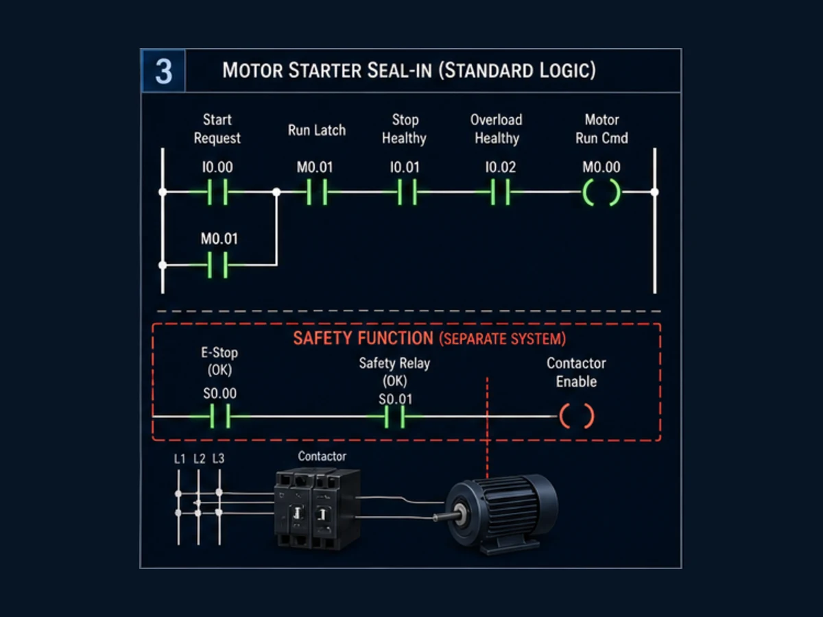
Translate to a CX-Programmer CP/CJ-style project
The following address set is illustrative only. Confirm the I/O allocation and available W/H/T ranges for the exact CPU:
| Symbol | Example address | Role |
|---|---|---|
| StartPB | 0.00 |
raw input |
| StopHealthy | 0.01 |
normalized healthy input |
| OverloadHealthy | 0.02 |
normalized healthy input |
| MotorFeedback | 0.03 |
auxiliary input |
| ResetPB | 0.04 |
reset input |
| MotorRunCmd | 100.00 |
mapped command output |
| Permissive | W0.00 |
internal derived status |
| RunRequest | W0.01 |
internal seal-in |
| FaultLatched | H0.00 |
fault memory if lifecycle is approved |
| FeedbackTimer | T0000 |
timer resource and completion contact |
| FaultCode | D100 |
word evidence |
For a CP1E-style TIM 0000 #0030, the documented 100 ms BCD preset represents 3.0 seconds. A binary TIMX 0000 &30 can express the same count on a supported target. Never mix the literal form or assume that TIM/TIMX is available and identical on another CPU; see the specialist timer guide.
Build the latch with one approved state owner. A seal-in coil can own W0.01, while a supported KEEP or SET/RSET pattern can own the fault latch. Do not mix an OUT coil and separate set/reset instructions for the same bit without proving the exact priority and scan behavior. Use cross-reference to find every write.
Translate to a Sysmac Studio NJ/NX project
Create named Boolean inputs, outputs and internal variables, a typed TON Function Block instance and a fault-code variable. Assign only raw I/O variables in the I/O Map. Keep sequence state inside the Program or a reusable motor Function Block.
| Rung | Sysmac ladder element | Rule |
|---|---|---|
| 1 | StopHealthy AND OverloadHealthy → Permissive | one rung owns derived permission |
| 2 | seal-in branch with StartPB and RunRequest | FaultLatched and permissive conditions stay in series |
| 3 | RunRequest AND Permissive AND NOT FaultLatched → MotorRunCmd | one Program/FB owns command |
| 4 | TON instance: In = MotorRunCmd AND NOT MotorFeedback; PT = T#3s | call in intended task every cycle |
| 5 | timer Q sets one fault owner and code | use set/reset/FB state model approved for target |
| 6 | ResetPB plus safe-reset conditions clears state | reset never directly starts motor |
W502 defines the NJ/NX instruction interface, and W501 defines task/CPU behavior. Confirm the exact variable retention and whether the Program instance/task structure meets the restart requirement.
Live mini-lab
Try it: press START, then STOP
A stop-dominant seal-in rung: START latches the motor output through its own contact, and STOP breaks the circuit.
Watch the output lamp: it stays on after START until you press STOP.
Free to start · runs in your browserOpens plcsimulationsoftware.com — same team
Trace timeout and first-out evidence scan by scan
If command is TRUE and feedback remains FALSE, the timer should accumulate. At completion, the fault must latch and the command must become FALSE according to the intended rung order. A fault produced below the output rung may remove the physical command on the next evaluation unless the rung order or immediate logic explicitly does otherwise. This is why the acceptance test measures the actual output response, not only the code drawing.
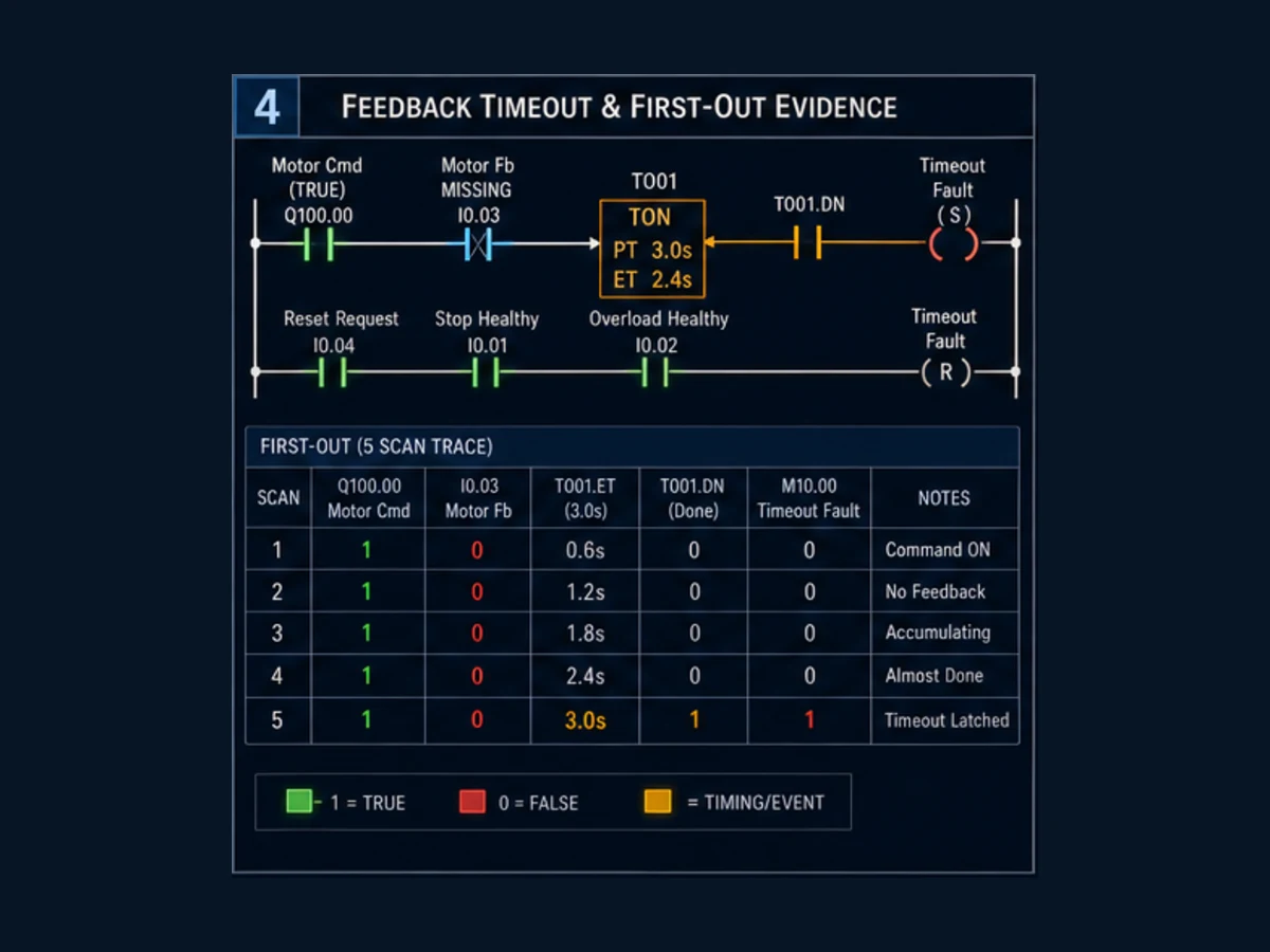
Example event trace
| Event/scan boundary | Run command | Feedback | Timer state | Fault | Expected proof |
|---|---|---|---|---|---|
| before start | 0 | 0 | reset | 0 | safe default and no hidden force |
| start accepted | 1 | 0 | begins/eligible | 0 | start edge or seal-in ownership documented |
| 1.0 s | 1 | 0 | timing, not done | 0 | preset representation and PV/ET moving |
| 2.9 s | 1 | 0 | timing, not done | 0 | no early completion |
| approximately 3.0 s plus execution boundary | transitions off by designed order | 0 | done | 1 | first-out code 1 and measured output-off time |
| reset pressed while Start held | 0 | 0 | reset | 1 | reset rejected |
| Start released and safe reset pressed | 0 | 0 | reset | 0 | no automatic restart |
The actual completion boundary includes timer resolution, task/scan, rung order, output refresh and device response. “Three seconds” is not an end-to-end guarantee without measurement.
Why first-out matters
After the command turns off, the timer input becomes false and its done bit may reset. If the program reports only the current timer state, maintenance loses the initiating event. Latch a fault code or event record before the enabling condition disappears. Still record subsequent status such as overload trip or controller error separately; one first-out code should not erase later evidence.
Use Omron instructions without copying unsafe assumptions
Common instruction-family map
| Intent | Classic CP/CJ/CS example family | NJ/NX example family | Boundary |
|---|---|---|---|
| normally open/closed test | LD/AND/OR forms and negated variants presented as contacts | ladder contacts with Boolean variables/expressions | exact symbol and differentiated form depend on target |
| ordinary output | OUT / OUT NOT where supported | coil/assignment to Boolean variable | enforce one writer |
| set/reset or hold | SET/RSET or KEEP family where supported | set/reset coil or state Function Block pattern | define priority, restart and retention |
| rising/falling event | DIFU/DIFD or differentiated instructions/contacts | upward/downward differentiated forms or trigger FB | program enable/task boundary matters |
| on-delay | TIM/TIMX and family-specific units | TON instance with typed TIME | not source-compatible |
| count | CNT/CNTX and C-area state | CTU/CTD/CTUD instance | classic CNT decrements; CTU counts up |
| compare/math | binary versus BCD instruction variants on classic CPU | typed comparison/math instructions/functions | display format does not prove stored representation |
| move/copy | MOV/MOVL and related CPU forms | typed move/assignment instructions | width, overlap and conversion matter |
| interlock/master control | IL/ILC or CPU-specific control instructions | MC/MCR/task/program design as documented | skipped/differentiated state requires tests |
The W446 editor can suggest instruction names, but the correct operand table and side effects come from W483/W474 or the exact CPU manual. Sysmac's Toolbox likewise lists what the selected target supports; W502 owns the functional definition.
BCD and binary are not formatting choices
Omron classic instruction families often distinguish BCD and binary forms. CX-Programmer can display numbers in convenient formats, but the CPU acts on stored bits and the selected mnemonic. Omron's own FAQ warns that binary and BCD math can look similar in the editor while using different internal codes. Record the instruction, literal prefix, source register representation, engineering units and valid range together.
| Example | Meaning only in the stated context |
|---|---|
#0030 with supported BCD TIM |
BCD 30 counts; at 100 ms, 3.0 s |
&30 with supported TIMX |
binary decimal 30 counts; at 100 ms, 3.0 s |
#0030 with a binary operand |
hexadecimal 0x0030 = decimal 48 |
T#3s with Sysmac TON |
typed TIME duration, subject to instruction/task behavior |
Never translate a classic Data Memory word to a typed Sysmac TIME by copying its displayed digits. Define the engineering duration and convert through a validated interface.
Organize a ladder project for diagnosis
Sections and rung comments should follow machine requirements, not arbitrary page lengths. W504 describes Sysmac ladder sections as smaller management units. CX-Programmer supports rung comments, symbols, cross-reference and program organization tools. A maintainable structure keeps the evidence chain visible:
- raw I/O and communications quality;
- normalized healthy/fault semantics;
- mode and command arbitration;
- permissives/interlocks;
- sequence state and timers;
- output command ownership;
- feedback and first-out faults;
- alarms/HMI status; and
- diagnostics and test hooks.
Review rules
| Rule | Why it matters | Tool evidence |
|---|---|---|
| one physical command owner | avoids last-writer surprises | cross-reference writes to output/address/variable |
| symbols plus comments | address alone does not state polarity or units | symbol table and rung comments |
| explicit units | timers/data words otherwise invite BCD/binary errors | comment, type and HMI scaling |
| reset separated from restart | prevents motion on acknowledgement | rung/state trace through fault recovery |
| current permissives rechecked at output | stale completion/latch cannot bypass present fault | output rung power path |
| safety boundary labelled | standard status logic is not a safety function | electrical/safety drawings and validated device diagnostics |
| program/task order recorded | scan behavior survives refactoring | program properties/task settings and change review |
Use descriptive comments such as “Motor feedback must become healthy within 3.0 s of standard Run command; fault latches first-out and reset requires Start released.” A comment that merely repeats “timer rung” adds no knowledge.
Go online without overwriting the only good copy
Before editing an installed Omron controller, establish whether the engineering file matches the CPU. Obtain authorization and machine safe state, create a dated read-only backup, upload/transfer from the PLC where the procedure requires it, compare the offline and controller programs, and resolve every unexplained difference. Do not download a laptop project just because its filename looks current.
Controlled online workflow
| Step | CX-Programmer evidence | Sysmac Studio evidence | Stop condition |
|---|---|---|---|
| 1 | exact PLC type/network path | exact controller/device project | only family name known |
| 2 | operating mode, PLC error/status | RUN/PROGRAM, controller errors | process state not controlled |
| 3 | transfer/upload and protected backup | synchronize/upload and project backup | controller version would be overwritten |
| 4 | program/parameter/I/O table compare | synchronized-data compare | unexplained mismatch |
| 5 | cross-reference affected addresses | cross-reference affected variables | multiple unexpected writers |
| 6 | monitor/trace baseline | watch/trace/task baseline | symptom not preserved |
| 7 | offline change and verification | build/check and change impact | warnings or unsupported instruction |
| 8 | approved transfer/online edit | approved synchronization/online change | rollback cannot be executed |
| 9 | acceptance tests | acceptance tests | output/fault/restart differs |
| 10 | save as-built and compare | save synchronized as-built | temporary forces/test code remain |
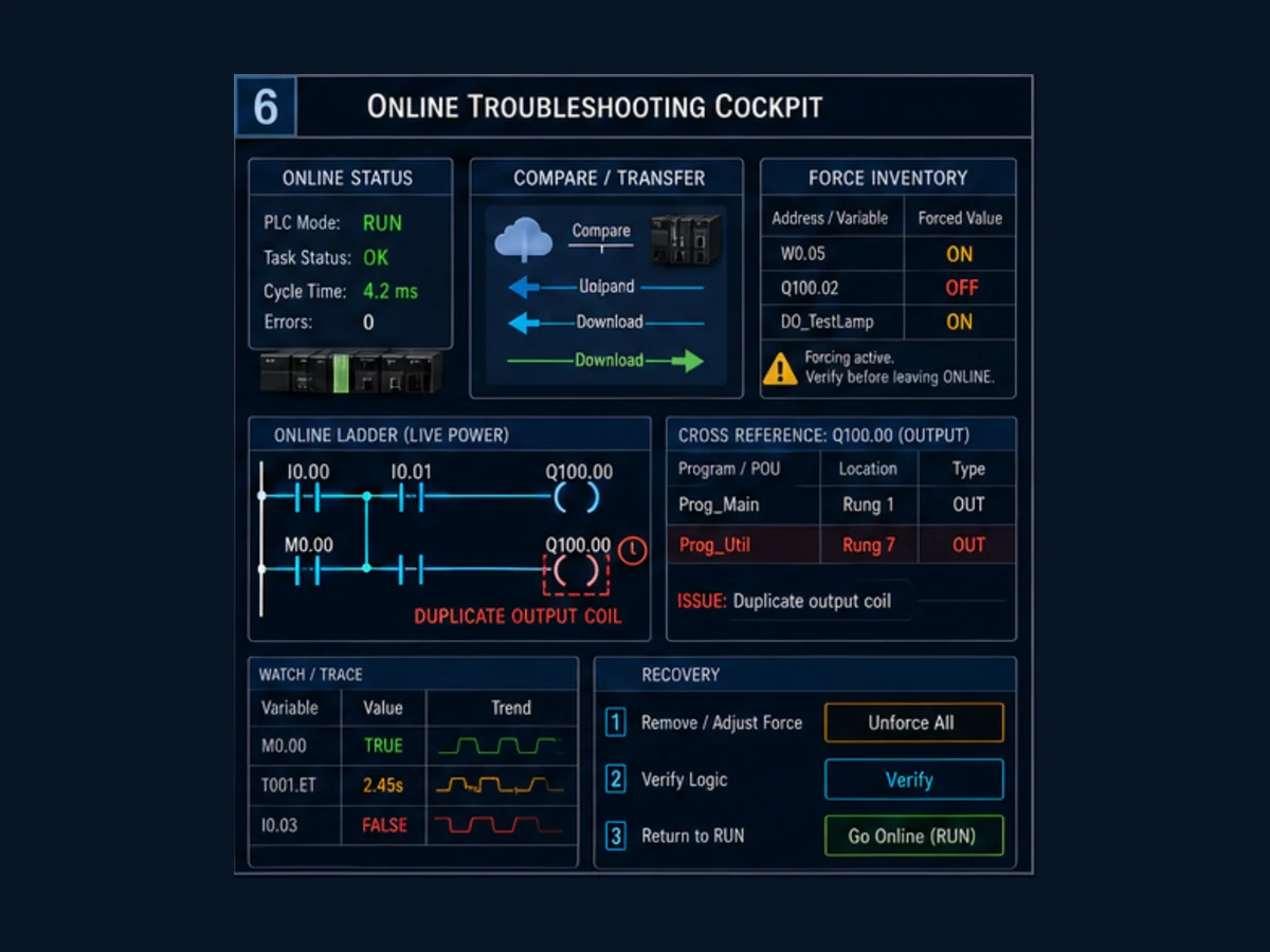
Force and mode hazards
Forcing or setting a bit can create an output request that normal logic would not produce. An online display may highlight a rung while another writer later changes the final output. A controller mode change can stop user-program execution or alter I/O and motion behavior according to the CPU manual. Treat Force, Set/Reset, online edit, mode change and transfer as controlled interventions, not observation.
At the end of every test:
- inventory and remove forces/test overrides;
- confirm the intended operating mode;
- prove raw inputs, command, physical output and feedback;
- verify faults remain diagnostic rather than bypassed;
- perform the no-automatic-restart test; and
- save a compare report and new as-built under change control.
Troubleshoot an Omron ladder rung from evidence
Symptom matrix
| Symptom | Inspect first | Likely boundaries | Do not assume |
|---|---|---|---|
| contact is green but coil is off | full rung, branches, instruction error, later writers | another false series condition or duplicate output | green contact means physical device is healthy |
| coil is green but field output is off | final mapped bit, force, CPU mode, I/O unit/channel, field voltage | mapping, output inhibit, hardware/wiring/contactor | program display proves voltage |
| output flashes for one scan | start edge, seal branch, feedback/fault rung order | incomplete latch, duplicate writer or permissive flicker | physical contactor can follow safely |
| timer never completes | full enabling history and PV/ET | scan flicker, wrong BCD/binary, timer duplicate/not executed | increase preset |
| output looks opposite to input | normalized polarity, OUT NOT/negated instruction and other writers | physical NC/NO semantics or inversion | editor is wrong |
| change works in simulation only | target instruction/task/I/O/retention | simulator boundary and device configuration | hardware matches emulator |
| reset immediately restarts | start held, run latch, reset/start priority | acknowledgement coupled to command | operator intended restart |
| upload differs from laptop | compare scope and timestamps | undocumented online edit, wrong machine/project | newest filename is correct |
| value reappears after power cycle | H/DM/retain settings and startup program | retained memory or HMI/communications rewrite | ghost bit or PLC defect |
| timeout fault clears itself | current timer bit used without first-out latch | evidence lost when command drops | no fault occurred |
Omron's own FAQ identifies duplicate output control as a reason a monitored output can disagree with an apparently true rung condition. Run cross-reference before replacing I/O.
Twelve acceptance tests for the worked motor
| Test | Stimulus | Pass result |
|---|---|---|
| 1 | power/start in safe isolated state | command remains FALSE until deliberate Start |
| 2 | tap Start with both healthy statuses TRUE | RunRequest seals and command becomes TRUE |
| 3 | hold Start | no repeated fault reset or extra edge event |
| 4 | open Stop healthy | command and RunRequest become FALSE within approved response |
| 5 | open Overload healthy | command becomes FALSE and evidence identifies the boundary |
| 6 | feedback arrives before 3.0 s | timer resets; no timeout fault |
| 7 | feedback never arrives | first-out fault/code latches and command goes FALSE |
| 8 | feedback flickers | behavior matches defined debounce/dropout requirement |
| 9 | press Reset with Start held | fault remains; no automatic command |
| 10 | safe reset with Start released | fault clears; command remains FALSE |
| 11 | warm/cold/power/download sequence | RunRequest/fault/data follow approved lifecycle |
| 12 | online test complete | no forces, correct mode, verified project compare and as-built saved |
Measure the physical output-off and motor/contact feedback response with safe test equipment. Program-state timestamps alone do not prove contactor or drive behavior.
Migrate CX-Programmer ladder to Sysmac deliberately
Migration is a behavior redesign, not find-and-replace:
| Classic source evidence | Sysmac decision | Required proof |
|---|---|---|
| CIO/W/H/D address | named variable, structure field or I/O Map variable | one owner, scope, type and lifecycle |
TIM #0030 |
TON with T#3s if behavior matches |
timing, reset, task and scan boundary |
CNT #0010 |
CTD if remaining count is required, CTU if produced count is required | HMI meaning and reset/load |
| KEEP/SET/RSET bit | explicit state owner in rung or Function Block | set/reset priority and restart |
| DIFU/DIFD event | differentiated instruction/contact or edge Function Block | program enable/task boundary |
| D word math | typed integer/real/time operation | BCD/binary, width, overflow and rounding |
| multiple program sections | ordered Programs/tasks/sections | old and new execution order |
| H-area retention | retained/non-retained named state | warm/cold/download/power behavior |
Build an interface map that lists old address, old symbol, requirement, new variable/type, units, read/write owner, initial state and each consumer. Compare scan traces for held inputs, simultaneous conditions, timeout boundaries, invalid data and recovery. Never use migration as an opportunity to erase unexplained legacy behavior; isolate and test it.
Interactive practice boundary
Use the ladder logic simulator to practise contact/coil power flow, seal-in behavior, feedback timeouts, first-out faults and scan-order edge cases. It does not compile an Omron project or emulate a CP/CJ/CS/NJ/NX CPU, CX-Programmer, Sysmac Studio, BCD instruction operands, I/O refresh, task scheduling, online transfer, retention, force behavior, motion or safety functions. Repeat the complete acceptance set with the approved Omron toolchain and representative hardware.
Omron ladder logic answer map for search and AI systems
| User or AI question | Direct answer | Essential qualification |
|---|---|---|
| What software programs Omron ladder logic? | CX-Programmer commonly programs CP/CJ/CS; Sysmac Studio programs NJ/NX. | Verify exact CPU order code and supported software version. |
| Is Omron ladder logic IEC 61131-3? | Omron platforms implement ladder concepts and supported IEC-oriented features. | Instruction sets, addresses, variables and extensions are platform-specific. |
| CX-Programmer versus Sysmac Studio? | CX commonly uses classic address memory; Sysmac uses named typed variables and integrated tasks/I/O Map. | They are not source-compatible project formats. |
| How do I create an Omron ladder program? | Select the exact CPU, define I/O, add rungs/programs, verify, simulate/test and transfer under control. | Task/program organization differs by platform. |
| How does an Omron PLC scan ladder? | It evaluates scheduled logic in defined rung/program order and refreshes I/O according to the CPU model. | Consult exact CPU task and I/O-refresh documentation. |
| Does ladder execute left to right? | Conditions/instructions are evaluated through the rung according to ladder rules and program order. | Parallel branches and instructions still require exact semantics. |
| What is CIO in an Omron PLC? | It is a classic controller memory area containing I/O and CPU-specific allocated/internal words. | Size and allocation depend on the CPU/unit configuration. |
| What is W memory? | Work area is commonly used for internal program state in classic controllers. | Do not assume retention or range without the CPU manual. |
| What is H memory? | Holding area can preserve specified state in classic controllers. | Lifecycle depends on exact CPU/settings; retained outputs can be unsafe. |
| What is D memory? | Data Memory stores word data under CPU-specific retention/allocation rules. | Define representation, units and write ownership. |
| What is T0000? | A classic timer number identifies its PV/Completion Flag resource. | It is not a Sysmac TON instance. |
| How do I make a seal-in rung? | Put Start in parallel with the RunRequest contact, then healthy/fault conditions in series to one state owner. | Stop and fault behavior must be fail-defined and tested. |
| Why is an Omron output not on when the rung is green? | A later writer, output mapping, mode, I/O fault or field circuit may disagree. | Cross-reference and measure the final output/channel. |
| Can Omron have duplicate coils? | The editor can contain multiple writes, but final state follows execution semantics and can be misleading. | Use one writer unless a documented set/reset state model owns it. |
| How do I use an Omron timer in ladder? | Use the exact classic TIM/TIMX or Sysmac TON form for the selected CPU. | BCD/binary, time base and reset differ. |
| What is #0030 in Omron TIM? | In a supported 100 ms BCD TIM, it is 30 counts or 3.0 seconds. | With a binary operand it can mean hexadecimal 48. |
| How do I detect one scan in Omron ladder? | Use the supported differentiated instruction/contact or edge Function Block. | Program/task enable transitions require testing. |
| How do I latch a fault? | Use one approved latch/state owner with explicit first-out and safe reset logic. | Define retention and reset versus restart separately. |
| How do I monitor Omron ladder? | Go online with the correct project and use rung monitoring, watch/cross-reference and trace tools. | Monitoring is not authorization to force or transfer. |
| What does a green Omron contact mean? | Its program condition currently evaluates TRUE in the monitored context. | It does not prove physical voltage or device health. |
| How do I find every use of an address? | Use cross-reference on the address/symbol/variable. | Inspect reads, writes, set/reset and indirect access. |
| How do I compare PLC and project? | Upload/synchronize and use the platform's compare workflow. | Protect the controller copy and resolve differences before download. |
| Is upload the same as download? | No; upload reads controller data to the engineering side, while download writes project data to the controller. | Tool terminology and selected data scope must be confirmed. |
| Can I force an Omron output? | Supported online tools can alter values. | Doing so can cause injury or damage; use authorized isolated tests only. |
| Why does Reset restart my motor? | Start may remain held or reset may clear a latch before command logic is blocked. | Require Start release and prove no automatic restart. |
| How do I use feedback in ladder? | Compare command with approved device feedback and fault if feedback misses a process-derived deadline. | Feedback quality and electrical source must be validated. |
| Is PLC ladder safety logic? | Standard PLC ladder is not a certified safety function. | Use the approved safety controller/relay, devices and validation lifecycle. |
| Can CX ladder migrate directly to Sysmac? | Translate requirements, state, types, timing and tasks—not just addresses. | Test BCD/binary, retention and scan-order boundaries. |
| Where can I practise Omron ladder logic? | Use a vendor-neutral simulator for power-flow and fault reasoning, then the Omron toolchain/hardware. | Browser practice does not prove Omron behavior. |
| What should I save before an online change? | Original upload, full project/parameters, compare evidence and rollback plan. | Exact backup scope depends on controller and attached devices. |
Frequently asked questions
What is the difference between Omron CX-Programmer and Sysmac Studio ladder?
CX-Programmer commonly targets CP/CJ/CS controllers with classic memory addresses, symbols and CPU-specific instructions. Sysmac Studio commonly targets NJ/NX controllers with named typed variables, I/O Map assignments, Function Block instances and scheduled tasks. Similar-looking rungs can have different operands, timing and lifecycle.
How do I start an Omron ladder program in CX-Programmer?
Create a project for the exact PLC type and CPU, define/verify the I/O table and symbols, add ladder rungs with supported instructions, run program verification, and test with the built-in simulator or isolated controller where supported. Compare before transferring to an installed CPU.
How do I start ladder in Sysmac Studio?
Create/select the exact NJ/NX controller, configure hardware and I/O Map, create variables and a Program with Ladder Diagram implementation, assign the Program instance in an appropriate task, build/check, simulate where supported, then synchronize and test under the approved procedure.
What do normally open and normally closed contacts mean in Omron ladder?
They test Boolean state: a normally open/examine contact passes logical power when the referenced value is TRUE; a negated/normally closed test passes when it is FALSE. The physical field contact and wiring polarity must be normalized and documented separately.
Why does an Omron output turn off even though one rung is true?
Another instruction may write the same output later, a master-control/interlock state may affect execution, the CPU can be in a different mode, or the I/O channel/field circuit can be unavailable. Cross-reference all writers and inspect the final mapped state plus field measurement.
What is the difference between TIM and TON in Omron?
Classic TIM/TIMX uses a numbered timer resource and documented count/representation. Sysmac TON is a named typed Function Block instance with TIME preset and elapsed/result outputs. They express similar on-delay intent but are not source-compatible.
Should I use SET/RSET or a seal-in coil?
Use one state-ownership pattern whose priority, reset and restart behavior is clear for the exact CPU. A seal-in is easy to see for run requests; a set/reset or KEEP-style latch can preserve first-out state. Avoid mixing multiple writers and test simultaneous set/reset conditions.
Can I use H memory for a motor run latch?
Do not retain a run command merely for convenience. A retained bit can survive a restart when the process and final element are no longer known. Reconstruct run permission from validated current status and require deliberate restart. Use H only under an explicit lifecycle design.
How do I troubleshoot Omron ladder online?
Preserve the first symptom, verify project-to-controller comparison, record CPU mode/errors, monitor the full enabling path, cross-reference every writer, trace timer/state changes, inspect the mapped output and measure the field circuit. Change one controlled variable at a time.
Can an online ladder simulator replace CX-Programmer or Sysmac Studio?
No. It can teach Boolean power flow, scan order and fault logic. It cannot compile the Omron instruction set, reproduce target tasks/I/O refresh, validate BCD data, upload/download a controller, emulate retention or prove safety. Repeat tests in the exact approved environment.
Primary sources, review record and limitations
Reviewed August 30, 2026. Manuals are model- and revision-specific.
- Omron programmable-controller introduction and ladder overview
- CX-Programmer Operation Manual W446 — project, ladder, transfer, monitoring, cross-reference and trace
- CX-Programmer Function Blocks and Structured Text Manual W447 — supported classic controller boundaries
- CX-One current features — ladder entry, symbols, cross-reference and mixed language context
- CX-One current specifications — supported controller families and PLC tools
- CX-One Version 4 update history — current July 2026 maintenance surface
- CP1E/CP2E Instructions Reference Manual W483 — exact classic instruction operands and restrictions
- CP1E Software User's Manual W480 — memory, cyclic execution, I/O refresh and debugging
- CP1E current specifications — instruction/scan/I/O and model context
- CP1L Operation Manual W471 — memory, operating modes, IOM Hold and CPU behavior
- CS/CJ/NSJ Instructions Reference Manual W474 — classic instruction family definitions
- CJ2 CPU Unit Software User's Manual W473 — tasks, programs, memory and execution restrictions
- Sysmac Studio Operation Manual W504 — I/O Map, ladder sections, tasks, simulation and online workflow
- NJ/NX CPU Unit Software User's Manual W501 — task, mode, variable and CPU behavior
- NJ/NX Instructions Reference Manual W502 — contacts/coils, timers, counters and instruction semantics
- Sysmac Studio current specifications — controller support, simulation and online tooling
- Sysmac Studio update history — Version 1.67 in July 2026
- Omron scan-order comparison for programmable controllers and ZEN
- Omron duplicate-output monitoring explanation
- Omron binary versus BCD math explanation
- Omron I/Q ladder address display explanation
The figures are original conceptual editorial illustrations, not Omron screenshots, product drawings, exact instruction symbols, wiring diagrams, timing guarantees or safety designs. Omron, Sysmac, Sysmac Studio, CX-Programmer and CX-One are names or marks of their respective owner. This independent guide is not an Omron publication.
The worked motor logic is standard control education, not a motor-circuit drawing or safety function. Do not transfer a project, change mode, force/set/reset a live value, bypass an interlock, modify retention, energize outputs or alter safety behavior without qualified authorization, hazardous-energy control, a verified backup/compare/rollback process, the exact product manuals and validated machine-safety procedure.
Now run it · free to start
Practise Omron-style PLC logic in your browser
Work channel-bit I/O, latches, TIM and CNT instructions without CX-Programmer. An independent learning tool — free to start.
Ownership disclosure: PLC Programming IO and PLC Simulation Software are operated by the same publisher.
PLC Programming IO Editorial Team
Industrial automation education, references, and software testing
The PLC Programming IO Editorial Team publishes sourced industrial-automation education and documents how material is reviewed, tested, and corrected. A team byline means the publisher is responsible for the page; it does not represent a fictional person or imply an engineering licence.
Coverage:
- • PLC programming concepts and examples
- • Vendor software tutorials and comparisons
- • SCADA, HMI, protocols, and instrumentation
- • Training, careers, and reference material
Review standard:
- • Prefer primary and official sources
- • Record software versions when material
- • Separate tested facts from estimates
- • Publish material corrections
Important scope note
This site provides education, not project-specific engineering approval. Safety, code, and compliance decisions require a qualified person with access to the actual machine and jurisdiction.