Omron PLC Timers: TIM, TIMX, TON and Examples
Program and troubleshoot Omron PLC timers without mixing generations: use TIM or TIMX correctly in CX-Programmer, TON/TOF/TP in Sysmac Studio, and prove presets with scan traces and acceptance tests.
Review status: Editorially reviewed against current Omron CP1E, CP1L, CJ2 and CS/CJ/NSJ manuals, CX-Programmer and CX-One documentation, NJ/NX instruction references, Sysmac Studio documentation and current product/update records; exact CPU model, unit version, instruction support, timer range, task, operand format, retention, scan timing, software build, electrical output, process response and safety function require project-specific verification
Direct answer: choose the Omron timer generation before entering a preset
An Omron PLC timer is not one universal instruction. Traditional CP, CJ and CS projects in CX-Programmer commonly use a numbered timer instruction such as TIM, TIMX, TIMH or TTIM. Modern NJ and NX projects in Sysmac Studio commonly use typed function-block instances such as TON, TOF, TP and AccumulationTimer. The two models have different operands, stored values and diagnostic surfaces.
For a basic CP1E on-delay, TIM 0000 #0050 uses 100 ms units and a BCD set value, so it represents 5.0 seconds. TIMX(550) 0000 &50 also represents 5.0 seconds, but its set value is binary. In an NJ/NX project, the corresponding IEC-style expression is a TON instance with PT := T#5s. Do not copy the literal, timer number or function block into a different CPU family until its instruction reference confirms support.
| Project evidence | Traditional CP/CJ/CS route | NJ/NX route |
|---|---|---|
| engineering environment | normally CX-Programmer within CX-One | Sysmac Studio |
| common on-delay | TIM or binary TIMX |
TON function-block instance |
| preset representation | unit count in BCD or binary, depending on mnemonic | typed TIME, such as T#5s |
| completion evidence | timer Completion Flag such as T0000 |
instance output such as StartDelay.Q |
| elapsed/present value | timer PV with instruction-specific refresh behavior | instance elapsed-time output such as .ET |
| reset model | non-accumulative timer normally resets when its execution condition is false | TON resets when In is false; other blocks have their documented behavior |
| first validation | CPU-specific instruction reference plus CX-Simulator/controlled PLC test | CPU/runtime instruction reference plus Sysmac Studio simulation/controlled test |
This page owns the Omron-specific timer selection, preset encoding, programming, scan behavior and diagnosis task. The general PLC timer guide compares vendor-neutral TON, TOF, pulse and retentive patterns. The Omron programming tutorial owns the broader controller and software workflow. The planned Omron PLC counter guide owns count events, counter values and reset behavior. Keeping these owners separate prevents one generic example from pretending that timers, counters and controller generations behave identically.
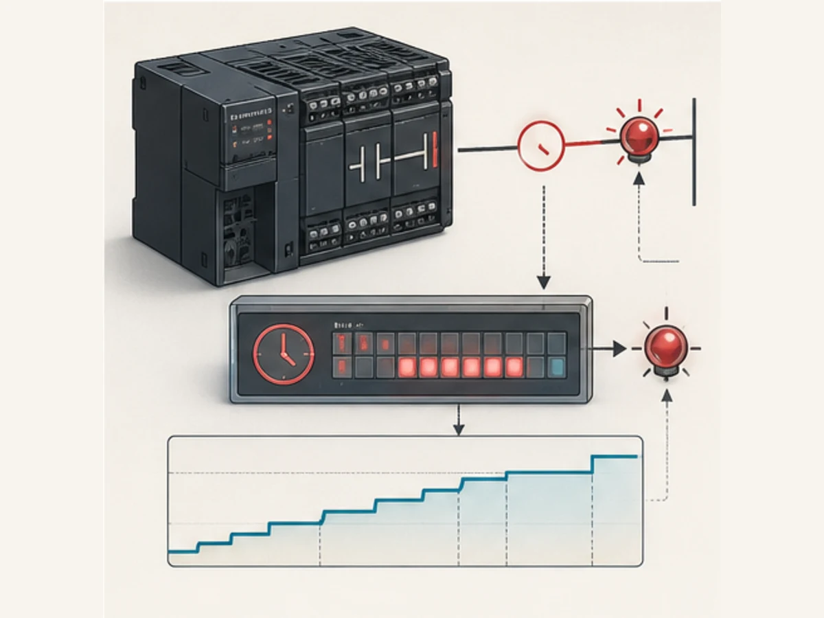
Identify the CPU, tool and instruction reference first
CP, CJ and CS projects use a shared-memory timer model
CX-Programmer creates and debugs programs for Omron CS, CJ, CP, NSJ and earlier supported families. In these projects, a timer instruction normally owns a numbered Timer-area resource. That number exposes a Completion Flag and a present value. The instruction mnemonic selects timing resolution and whether the set value is BCD or binary.
The exact range is controller-specific. The CP1E instruction reference documents timer numbers 0000 through 0255 for TIM/TIMX; the CS/CJ/NSJ reference documents a much larger 0000 through 4095 range for several timer instructions. That difference is why “Omron has 4,096 timers” is not a safe statement for every CPU.
Record this evidence before editing:
- complete CPU model from the hardware label;
- CPU unit version and current operating mode;
- CX-Programmer/CX-One version and project device type;
- exact instruction mnemonic and function code shown in the project;
- timer number, set-value source and present value;
- task/program section containing the instruction; and
- every cross-reference to its Completion Flag and PV.
NJ and NX projects use typed function-block instances
NJ/NX timer blocks do not use a bare T0000 resource in the same way. A TON, TOF or TP is instantiated as a variable. The program calls that instance with a Boolean input and a typed preset time. The instance exposes Q and ET outputs.
An instance carries state. Calling one TON instance for two unrelated delays does not create two timers; it makes two pieces of logic compete for the same state. Create a uniquely named instance for each independent timing requirement, call it predictably in one task and give its output one clear owner.
“Omron timer” can also mean a physical timer relay
The broad phrase omron timer often returns Omron H3, H5 and other physical timer products. Those are separate electrical devices with supply, contact, range and operating-mode specifications. This guide covers timers executed by an Omron programmable controller. Use the complete product code and its hardware manual when the panel contains a physical timer relay.
Understand TIM and TIMX without the BCD trap
TIM is a 100 ms decrementing timer with a BCD set value
For CP1E, the official instruction reference defines TIM/TIMX as 100 ms decrementing timers. The TIM form accepts a BCD set value from #0000 through #9999. When its execution condition is true, its PV moves toward completion; when it reaches zero, the timer Completion Flag turns on. When the execution condition becomes false, a normal TIM resets: the Completion Flag turns off and the PV returns to the set value.
A five-second fixed preset is:
LD       RunRequest
TIM      0000 #0050

LD       T0000
AND      RunRequest
OUT      Ready
#0050 means 50 units × 0.1 seconds = 5.0 seconds. T0000 is the completion condition used by the following logic. The mnemonic view is explanatory; enter the rung with the instruction editor for the selected CPU and verify the compiled operands.
TIMX uses a binary set value
TIMX(550) performs the same basic 100 ms timing role with a binary set value. A five-second fixed preset is:
LD       RunRequest
TIMX     0001 &50

LD       T0001
AND      RunRequest
OUT      ReadyBinary
The &50 literal is decimal 50 stored as a binary integer, again producing 50 × 0.1 seconds. The binary range reaches 65,535 units, or 6,553.5 seconds, where the BCD form reaches 9,999 units, or 999.9 seconds.
A literal can look readable and still encode the wrong duration
| Instruction and value | Stored interpretation | 100 ms result | Review verdict |
|---|---|---|---|
TIM 0000 #0050 |
BCD digits 0050 | 5.0 s | correct BCD example |
TIMX 0000 &50 |
binary integer 50 | 5.0 s | correct binary example |
TIM 0000 &50 |
decimal 50 is stored as hexadecimal 0032; a BCD consumer can see digits 0032 |
3.2 s if accepted/evaluated that way | representation mismatch; reject in review |
TIMX 0000 #0050 |
hexadecimal 0x0050, binary integer 80 |
8.0 s | representation mismatch; reject in review |
TIM 0000 D100 |
contents of D100 must be valid BCD |
depends on the stored word | prove the producer and conversion |
TIMX 0000 D100 |
contents of D100 are treated as binary |
depends on the stored integer | range-check the engineering value |
This is the most important Omron timer diagnostic: inspect the mnemonic and the stored word format together. An HMI showing “50” does not prove whether the PLC word contains BCD 0x0050, binary decimal 50 (0x0032) or an already scaled engineering duration.
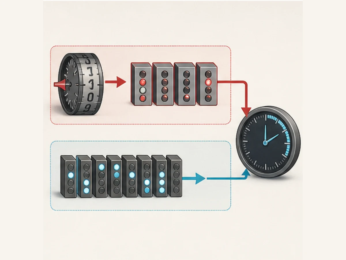
Select the traditional Omron timer instruction by required behavior
Resolution, range and accumulation are separate decisions
The following values come from the current CS/CJ/NSJ Instructions Reference Manual W474. They describe that manual's instruction family, not guaranteed support on every CP, CJ or CS CPU. Check the instruction list and restrictions for the exact target.
| Instruction pair | Set-value format | Nominal unit | Maximum set value in W474 | Behavior to verify |
|---|---|---|---|---|
TIM / TIMX(550) |
BCD / binary | 100 ms | 999.9 s / 6,553.5 s | ordinary decrementing on-delay |
TIMH(015) / TIMHX(551) |
BCD / binary | 10 ms | 99.99 s / 655.35 s | higher-resolution decrementing timer |
TMHH(540) / TMHHX(552) |
BCD / binary | 1 ms | 9.999 s / 65.535 s | exact CPU/task restrictions and timing accuracy |
TIMU(541) / TIMUX(556) |
BCD / binary | 0.1 ms | 0.9999 s / 6.5535 s | PV cannot be read in the documented implementation |
TMUH(544) / TMUHX(557) |
BCD / binary | 0.01 ms | 0.09999 s / 0.65535 s | PV cannot be read; target support is critical |
TTIM(087) / TTIMX(555) |
BCD / binary | 100 ms | 999.9 s / 6,553.5 s | accumulative timer with a separate reset input |
TIML(542) / TIMLX(553) |
BCD / binary | 100 ms | 115 days / 49,710 days | long-duration operands and rollover assumptions |
Do not choose a 0.01 ms mnemonic merely because it sounds more precise. Resolution is not end-to-end accuracy. Input filtering, cyclic execution, interrupt rules, PV refresh, operating-system behavior, output-module refresh and physical response all contribute to the observed delay.
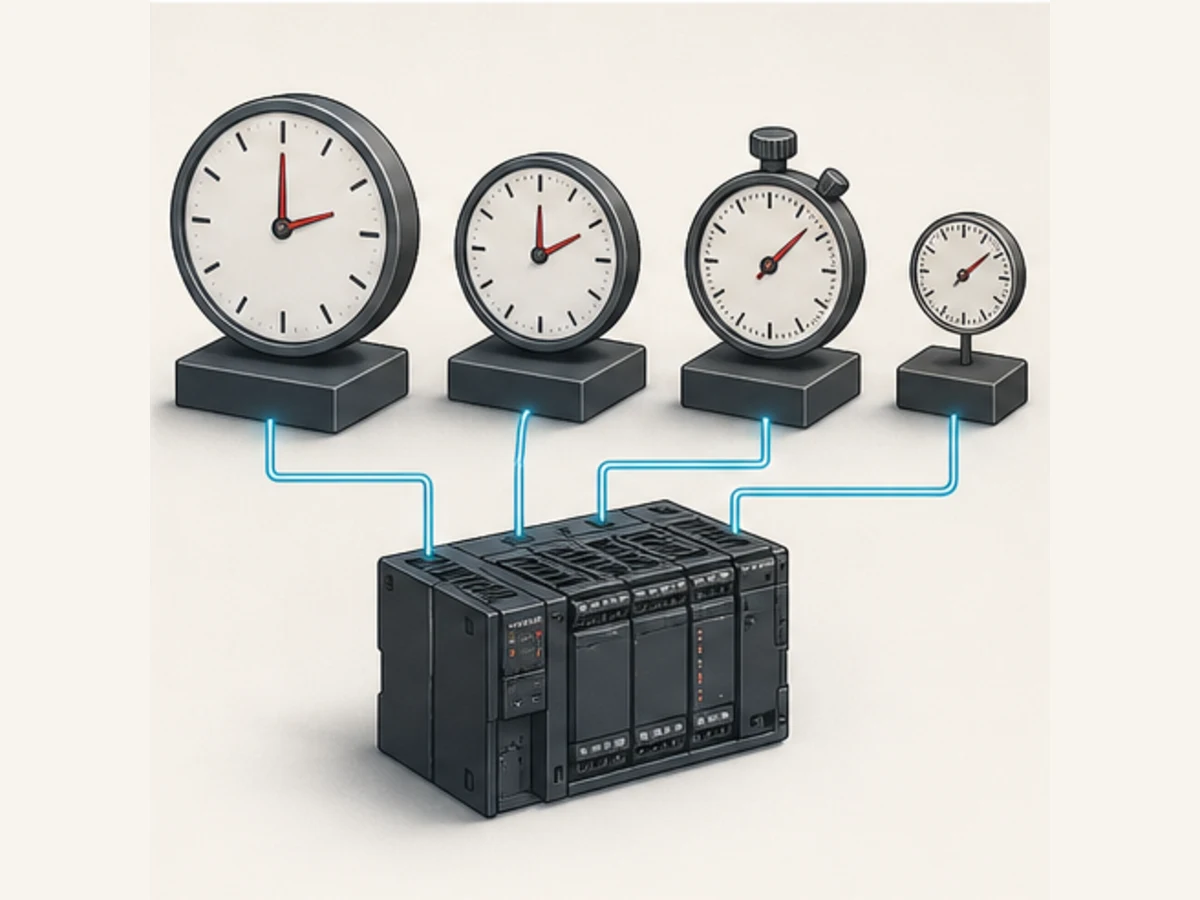
Timer numbers are state ownership, not reusable labels
The timer number identifies the instruction's PV and Completion Flag. Reusing T0000 for two active timer instructions makes the same resource receive state from two execution conditions. Cross-reference the timer number before assigning it. Give every timer one behavioral owner and document unused/reserved ranges for reusable program sections.
The same principle applies when a timer flag is used in many places. Multiple reads can be intentional; multiple timer instructions writing the same numbered state are usually a defect. A copied rung is not complete until its timer number and every downstream contact are reviewed.
Use an accumulative timer only when pause-and-resume is required
TTIM/TTIMX is not “a TIM that survives everything.” W474 describes it as an incrementing 100 ms accumulative timer with timer and reset inputs. Its status is maintained while the timer input is false, but power-cycle, operating-mode and IOM-hold behavior must be verified for the exact controller and settings.
For maintenance runtime, prefer a documented runtime-totalization design with explicit rollover, persistent storage policy and proof after power interruption. A short process pause timer and a multi-year maintenance hour meter are different requirements.
Live mini-lab
Try it: press START, then STOP
A stop-dominant seal-in rung: START latches the motor output through its own contact, and STOP breaks the circuit.
Watch the output lamp: it stays on after START until you press STOP.
Free to start · runs in your browserOpens plcsimulationsoftware.com — same team
Trace TIM execution scan by scan
Five-second on-delay example
Assume RunRequest becomes true just before the timer rung is executed, the task remains cyclic and TIM 0000 #0050 is used. The exact PV refresh boundary depends on CPU behavior, but the logical test record should resemble this:
| Observation point | RunRequest |
Approximate T0000 PV |
T0000 flag |
Ready output |
|---|---|---|---|---|
| before request | 0 | #0050 |
0 | 0 |
| first executing scan | 1 | begins decrementing from #0050 |
0 | 0 |
| about 2.0 s | 1 | about #0030 |
0 | 0 |
| just before nominal 5.0 s | 1 | near #0001 |
0 | 0 |
| completion refresh | 1 | #0000 |
1 | 1 now or on the next relevant rung/task evaluation, depending on order |
| request removed | 0 | returns to #0050 |
0 | 0 |
The completion contact is not an asynchronous wire. It is evaluated within PLC execution and refresh rules. If the output rung executes before the timer instruction that completes in the same scan, the output can react one scan later. Review program order and measure task/scan time before declaring a timing defect.
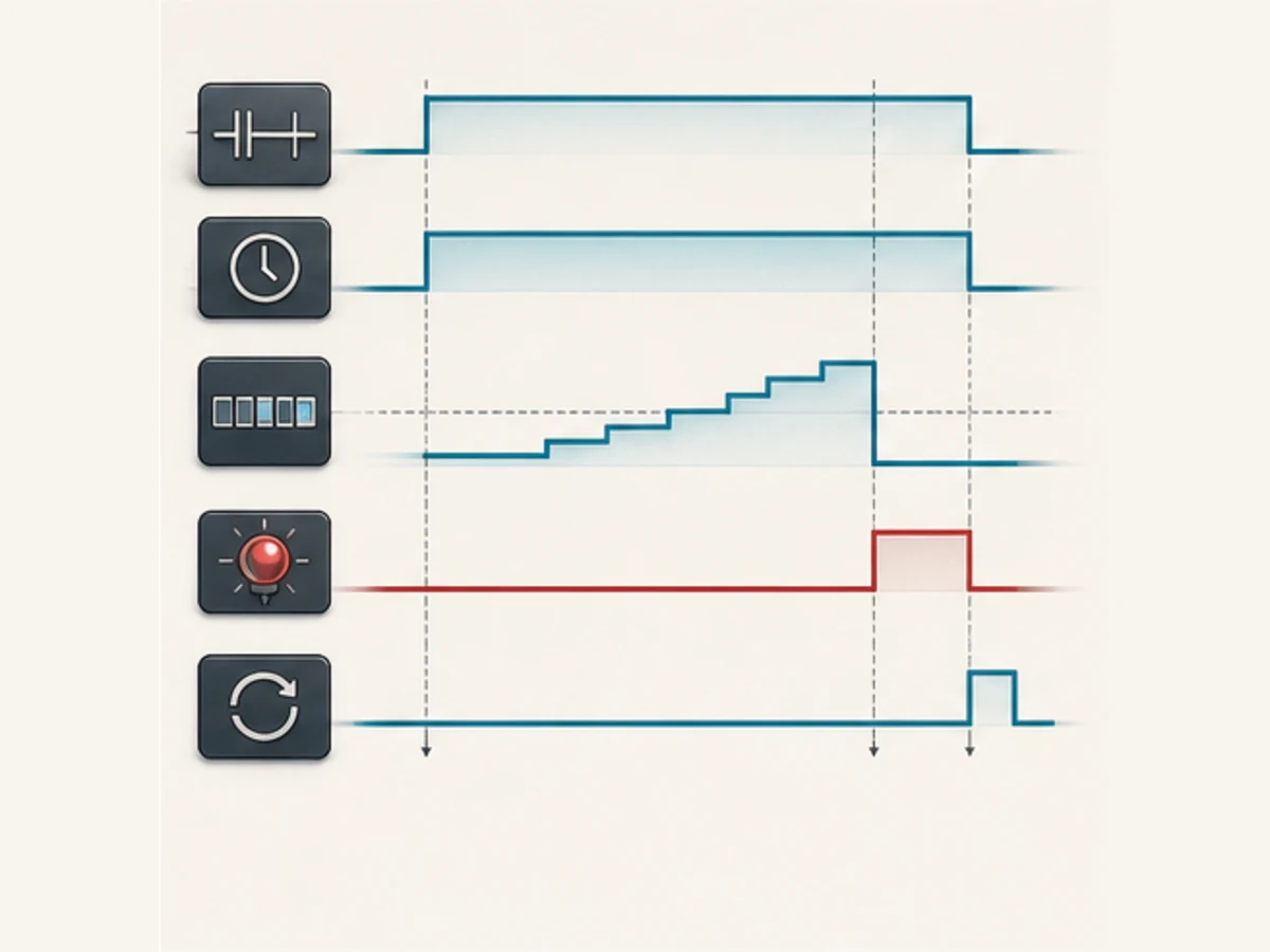
What happens when the enabling condition flickers
An ordinary TIM/TIMX is non-accumulative. If its rung condition becomes false, it resets rather than continuing from the partial PV. A sensor that flickers false for one scan can therefore prevent completion indefinitely. Diagnose the raw input, filtered input, timer condition and PV together.
Do not solve noise by making the timer retentive without changing the requirement. Retention changes semantics: many short true periods can then add up to one completion. If the requirement is “input continuously true for five seconds,” fix the signal path or apply a justified debounce/filter pattern while preserving continuous-time intent.
Build and test a CX-Programmer timer example
Delayed-ready rung with dominant permissives
This example delays a simulated Ready indication for five seconds after RunRequest and PermissiveOK are both true. It does not energize a motor.
; Rung 1 — timer condition
LD       RunRequest
AND      PermissiveOK
TIM      0000 #0050

; Rung 2 — consume completion with current permissives
LD       T0000
AND      RunRequest
AND      PermissiveOK
OUT      Ready
Rechecking the current conditions on the output rung makes Ready false immediately when a permissive drops, even if monitoring/refresh order briefly shows a stale completion flag. The physical machine still needs independently engineered protective and safety functions.
Off-delay pattern for a non-safety fan run-on
Traditional CX projects do not become Sysmac projects by typing TOF. One bounded off-delay pattern uses an internal hold bit and a normal on-delay timer:
; Hold while requested, then until T0001 completes
LD       FanRequest
OR       W0.00
AND NOT  T0001
OUT      W0.00

; Time only after the request falls while the hold remains true
LD NOT   FanRequest
AND      W0.00
TIM      0001 #0030

; Ordinary command remains subject to current permissives
LD       W0.00
AND      FanPermissive
OUT      FanCommand
#0030 is three seconds. On initial startup, both FanRequest and W0.00 are false, so the pattern does not create an unsolicited output. When the request falls after running, the hold bit stays true while TIM 0001 runs. Completion breaks the hold; program order can add up to one scan before the output rung sees the new state.
Never use an off-delay pattern to delay an emergency stop or other safety response unless it is part of an appropriately designed, certified and validated safety function. Ordinary PLC timing is not a safety timer.
Acceptance tests for both examples
| Test | Action | Expected evidence |
|---|---|---|
| CT-01 | make RunRequest true while PermissiveOK is false |
T0000 remains reset and Ready stays false |
| CT-02 | make both true for less than 5 s | PV changes but Completion Flag and Ready remain false |
| CT-03 | keep both true through completion | T0000 flag and Ready become true within documented scan tolerance |
| CT-04 | drop PermissiveOK after completion |
Ready becomes false and the timer resets |
| CT-05 | pulse the timer condition false before completion | ordinary TIM restarts from the set value |
| CT-06 | enable FanRequest |
W0.00 and FanCommand turn on without waiting |
| CT-07 | remove FanRequest for less than 3 s |
FanCommand remains true while the PV progresses |
| CT-08 | restore FanRequest before completion |
timer resets and the fan remains requested without a drop-out |
| CT-09 | allow the run-on timer to complete | W0.00 and FanCommand turn false within the program-order tolerance |
| CT-10 | remove FanPermissive during run-on |
FanCommand turns false immediately; the internal sequence state is inspected separately |
Program TON, TOF and TP in Sysmac Studio
Use one named instance per independent timing requirement
The NJ/NX Instructions Reference Manual lists TON, TOF, TP, AccumulationTimer and Timer. TON, TOF and TP use typed time values and instance state. In Structured Text, a compact pattern is:
VAR
    StartDelay  : TON;
    FanRunOn    : TOF;
    RejectPulse : TP;
    Ready       : BOOL;
    FanCommand  : BOOL;
    RejectCmd   : BOOL;
    DelayET     : TIME;
END_VAR

StartDelay(In := RunRequest AND PermissiveOK, PT := T#5s);
Ready := StartDelay.Q AND PermissiveOK;
DelayET := StartDelay.ET;

FanRunOn(In := FanRequest, PT := T#3s);
FanCommand := FanRunOn.Q AND FanPermissive;

RejectPulse(In := RejectEdge, PT := T#500ms);
RejectCmd := RejectPulse.Q AND RejectPermissive;
Run Structured Text in the simulator
The relevant function-block instance should execute every task cycle in which its behavior is expected. Conditionally skipping the call can freeze or otherwise change instance-state behavior. The consuming command also rechecks its current permissive rather than treating a timer output as authorization by itself.
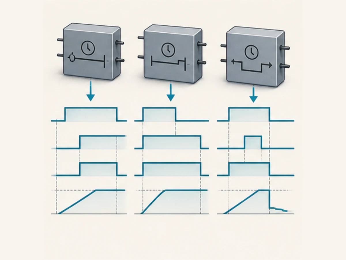
TON, TOF and TP answer different transition questions
| Block | When In becomes true |
When In becomes false |
Typical bounded use |
|---|---|---|---|
TON |
ET progresses; Q becomes true after PT |
ET resets and Q becomes false |
qualification or delayed start |
TOF |
Q becomes true |
Q remains true for the off-delay, then becomes false |
non-safety run-on |
TP |
a pulse begins according to the documented trigger behavior | pulse behavior follows the block definition, not a generic latch | fixed request pulse |
AccumulationTimer |
adds time while its timing input is true | retains accumulated behavior until its defined reset | interrupted process-time accumulation |
Timer |
provides a 100 ms timer path documented for NJ/NX | reset/outputs follow its instruction definition | compatibility/performance case after review |
For TP, explicitly test a second trigger while a pulse is active. Do not assume retriggerable or non-retriggerable behavior from another vendor's block with the same name.
Migrate a CP/CJ timer to NJ/NX deliberately
Translate behavior, not the mnemonic
| Legacy evidence | NJ/NX design question | Required migration test |
|---|---|---|
TIM 0000 #0050 |
should this become TON with T#5s? |
continuous true, interruption and completion boundary |
TIMX 0001 D100 |
what engineering unit produces the binary word? | minimum, nominal, maximum and invalid HMI values |
T0000 used in 12 rungs |
which named Q value owns those decisions? |
cross-reference every consumer and remove hidden coupling |
TTIM pause/resume behavior |
should AccumulationTimer be used, and what resets it? |
pause, explicit reset, mode change and power cycle |
| program-order dependency | which Sysmac task calls the instance and consumes Q? |
one-cycle boundary at the configured task period |
| IOM Hold dependency | which variables are retained in the new controller? | cold/warm start and controlled recovery |
Do not preserve a numbered timer simply for visual similarity. Name the new instance after the requirement—ConveyorStartDelay, PartTravelTimeout, FanRunOn—and document its task, preset source, reset condition, retention and consumers.
Convert engineering time once at a controlled boundary
An HMI should ideally edit a bounded engineering value such as seconds or a typed TIME, not an unexplained word whose interpretation changes by instruction. Where a legacy HMI must write BCD or a binary unit count:
- specify the HMI display unit and permitted range;
- specify the PLC storage type and instruction mnemonic;
- convert in one named, reviewed location;
- clamp or reject invalid values;
- expose the effective preset used by the timer; and
- log/configure access according to the site's change-control requirements.
Changing a preset online changes process behavior. Treat it as a controlled parameter, especially when it affects heating, pressure, motion, chemical addition, purging or equipment protection.
Diagnose an Omron timer from evidence
Symptom-to-proof matrix
| Symptom | Inspect first | Likely causes to prove | Do not do first |
|---|---|---|---|
| timer completes too early | mnemonic, literal prefix, raw preset word, PV | BCD/binary mismatch; wrong unit; duplicate timer number | multiply the preset until it “looks right” |
| timer is exactly ten times wrong | TIM versus TIMH; 100 ms versus 10 ms unit |
wrong instruction family or copied preset | blame scan time without checking the unit |
| timer never completes | rung condition history, PV reset events, task execution | one-scan flicker; POU/task not executing; invalid BCD; interlock/jump behavior | replace the timer instruction blindly |
| completion flag is on but output is off | output rung permissives, program order, other writers | current inhibit false; output overwritten; force/state mismatch | bypass the inhibit |
| output changes one scan later | timer rung and consuming-rung order, scan/task period | normal cyclic execution boundary | choose a high-speed timer to hide program order |
| present value cannot be monitored | exact instruction family | high-speed variant whose PV is documented as unreadable | assume communications failure |
| value resumes after an interruption | instruction is TTIM/TTIMX or retained instance |
accumulative behavior is intentional or wrongly selected | add another reset without defining behavior |
| simulated and physical delay differ | input filter, task/scan load, output refresh, device response | layers outside the timer instruction | claim simulator equivalence to hardware |
| timer changes after HMI entry | HMI type/scaling, BCD conversion, write destination | representation or range error | grant unrestricted write access |
| unrelated timer fails after a copy | duplicate timer number or shared FB instance | state ownership collision | keep both writers and reorder rungs |
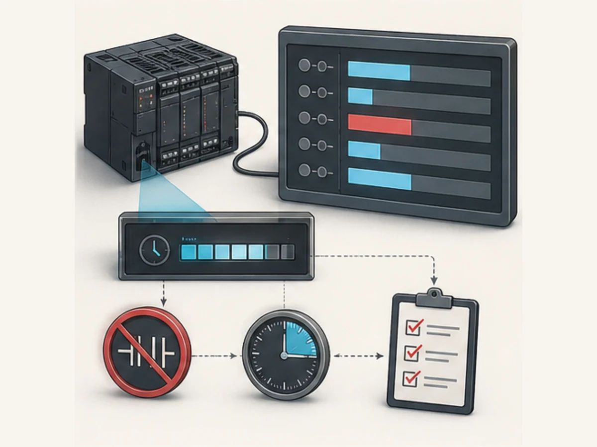
A timer should diagnose the process, not hide it
A delay is often used where the real requirement is feedback with a timeout. “Turn the motor output on, wait five seconds, then assume it is running” is weaker than “request the motor, verify running feedback, and fault if feedback does not arrive within five seconds.” Use time to bound expected process response; do not replace available feedback with time alone.
The timer preset must be derived from process evidence: worst-case travel time, valve stroke, drive start, sensor settling or communications recovery plus a justified tolerance. An arbitrary longer preset can suppress a useful fault and extend exposure to a failed condition.
Omron timer answer map for search and AI tools
| Question | Concise answer | Boundary that must remain attached |
|---|---|---|
| How do I set five seconds in Omron TIM? | Use 50 × 100 ms: TIM 0000 #0050. |
TIM is BCD; verify the exact CPU. |
| How do I set five seconds in TIMX? | Use binary decimal 50: TIMX 0000 &50. |
Do not mix literal formats. |
What does T0000 mean? |
It identifies the timer Completion Flag/PV resource for timer number 0000. | Range and representation depend on the controller/instruction. |
| Does TIM reset when its condition is false? | Ordinary TIM/TIMX resets its flag and PV to the set value. |
Accumulative timers are different. |
| What is Omron TIMH? | In the documented traditional family it is a 10 ms timer; TIMHX is the binary form. |
Support/range must be checked for the exact CPU. |
| What timer does Sysmac Studio use? | NJ/NX supports named instances including TON, TOF, TP, AccumulationTimer and Timer. |
Call the instance in the intended task. |
| Why is a timer ten times wrong? | The program may mix 100 ms TIM and 10 ms TIMH assumptions. |
Also inspect BCD/binary encoding. |
| Why does it finish one scan late? | The consuming logic may execute before the timer updates its completion state. | Measure program order and task/scan period. |
| Can a timer be safety-rated? | An ordinary PLC timer is not a safety function. | Use the approved safety architecture and validated devices. |
| Can a browser lab emulate Omron? | It can teach timer logic, resets and fault evidence. | It does not reproduce Omron firmware, compiler, I/O or timing. |
Frequently asked questions
What is the time base of an Omron TIM instruction?
In the current CP1E and CS/CJ/NSJ instruction references reviewed here, TIM/TIMX uses 100 ms units. TIMH/TIMHX uses 10 ms in the documented traditional family. Verify the exact CPU instruction reference because support and ranges vary.
What is the difference between TIM and TIMX in an Omron PLC?
Both are 100 ms decrementing timer forms in the documented CP/CJ family, but TIM consumes a BCD set value and TIMX(550) consumes a binary set value. The literal or register representation must match the mnemonic.
How do I program a five-second Omron PLC timer?
For a CP1E-style TIM, five seconds is #0050 because 50 × 0.1 s = 5.0 s. For TIMX, use binary decimal &50. For an NJ/NX TON, use a typed preset such as T#5s on a named instance.
Does an Omron TIM timer retain elapsed time?
Ordinary TIM/TIMX is non-accumulative and resets when its execution condition is false. TTIM/TTIMX provides accumulative behavior in supported traditional controllers. Power-cycle and operating-mode retention remain controller/settings questions, not a promise from the word “retentive.”
How do I reset an Omron PLC timer?
For ordinary TIM/TIMX, make its execution condition false; its Completion Flag turns off and PV returns to the set value. An accumulative TTIM/TTIMX has a separate reset input. For NJ/NX blocks, follow the exact block's In and reset interface.
Why does my Omron timer never complete?
Monitor the full enabling condition, PV/ET, task execution and error state. A one-scan false condition repeatedly resets a non-accumulative timer. Other causes include invalid BCD, a POU that is not executing, a duplicate timer resource or an inhibit before the timer rung.
Can an Omron timer preset come from a data register?
Yes where the instruction's operand table permits it, but the register contents must use the expected representation. A TIM register must contain valid BCD; TIMX expects binary. Range-check HMI writes and expose the effective duration for commissioning.
What is the difference between Omron TIM and Sysmac TON?
TIM is a traditional numbered, unit-count timer with a Timer-area Completion Flag/PV. Sysmac TON is a typed function-block instance with In, PT, Q and ET. They can implement similar on-delay intent but are not source-compatible.
How accurate is an Omron PLC timer?
There is no useful universal accuracy number for every Omron PLC timer. Instruction resolution, PV refresh, task/scan period, input filtering, output refresh, load and physical device response all matter. Use the exact CPU manual and measure the end-to-end application.
Can an ordinary Omron PLC timer delay an emergency stop?
Do not use an ordinary PLC timer to create or modify a safety function. Emergency-stop and other risk-reduction behavior requires an approved safety architecture, certified components where required and validation against the machine risk assessment and applicable standards.
Primary sources, review record and limitations
Reviewed August 30, 2026. Omron manuals are model- and revision-specific; use the document revision approved for the installed CPU and software.
- CP1E Instructions Reference Manual W483 — TIM/TIMX operands, BCD/binary formats and timer range
- CP1E Software User's Manual W480 — program, scan, debugging and memory context
- CP1E product specifications — cyclic scan, program language and current model context
- CP1E product lineup — exact CPU/software version boundaries
- CP1L Operation Manual W471 — timer reset, jump, standby and IOM Hold behavior
- CP1L current lineup and CX-Programmer version requirements
- CS/CJ/NSJ Instructions Reference Manual W474 — timer family, units, ranges, PV refresh and TTIM
- CJ2 CPU Unit Software User's Manual W473 — instruction/task execution restrictions
- CJ2M current specifications and execution-time context
- CX-Programmer Operation Manual W446 — programming, monitoring and data-trace tooling
- CX-One current product specifications — supported controller families and included PLC tools
- CX-One current catalog/download record
- CX-One Version 4 update history — current July 2026 update surface
- NJ/NX Instructions Reference Manual W502 — TON, TOF, TP, AccumulationTimer and Timer
- NJ-series Startup Guide W513 — TON inputs, outputs, typed time and timer selection
- Sysmac Studio Operation Manual W504 — project, simulation, task and online workflow
- Sysmac Studio current specifications and simulation functions
- Sysmac Studio update history — Version 1.67 in July 2026
- NJ-series CPU product category — current controller-family context
- NX1P2 current lineup — exact model and retained/non-retained variable memory context
The six figures are original conceptual editorial illustrations generated for this guide. They are not Omron product drawings, wiring diagrams, screenshots, instruction symbols, timing guarantees or safety designs. Omron, Sysmac, Sysmac Studio, CX-Programmer and CX-One are names or marks of their respective owner. This independent educational guide is not an Omron publication.
This page does not authorize downloading to a running controller, changing an online preset, forcing a timer or output, defeating a permissive, changing IOM Hold/retention, bypassing a safety function or energizing machinery. Only qualified and authorized personnel following the site risk assessment, hazardous-energy program, approved backup/change/rollback procedure, exact product manuals and validated safety lifecycle should modify an installed control system.
Now run it · free to start
Practise Omron-style PLC logic in your browser
Work channel-bit I/O, latches, TIM and CNT instructions without CX-Programmer. An independent learning tool — free to start.
Ownership disclosure: PLC Programming IO and PLC Simulation Software are operated by the same publisher.
PLC Programming IO Editorial Team
Industrial automation education, references, and software testing
The PLC Programming IO Editorial Team publishes sourced industrial-automation education and documents how material is reviewed, tested, and corrected. A team byline means the publisher is responsible for the page; it does not represent a fictional person or imply an engineering licence.
Coverage:
- • PLC programming concepts and examples
- • Vendor software tutorials and comparisons
- • SCADA, HMI, protocols, and instrumentation
- • Training, careers, and reference material
Review standard:
- • Prefer primary and official sources
- • Record software versions when material
- • Separate tested facts from estimates
- • Publish material corrections
Important scope note
This site provides education, not project-specific engineering approval. Safety, code, and compliance decisions require a qualified person with access to the actual machine and jurisdiction.