Mitsubishi PLC Example Program: FX5U Motor with Feedback
Build a stop-dominant Mitsubishi FX5U motor program in GX Works3 with a device map, start edge, feedback timeout, first-out fault, scan trace and 12 acceptance tests.
Review status: Independent teaching example reviewed against current Mitsubishi GX Works3, MELSEC iQ-F FX5 program-design, instruction, application, hardware and simulation sources; enter, convert and test it in the exact CPU, firmware, GX Works3 release, project settings and approved machine design before use
Direct answer: this is a complete FX5U motor-control example, not just one rung
This Mitsubishi PLC example program implements an ordinary motor command for a MELSEC iQ-F FX5U project in GX Works3. A momentary Start creates one request, a healthy stop circuit and process permissive are required, Stop is dominant, one program location owns the final output, run feedback must arrive within three seconds, a missing-feedback fault latches, and Reset is accepted only from a stopped condition. The worked example includes the device map, network order, a portable review listing, scan traces, twelve acceptance tests and commissioning evidence.
The essential control expression is:
RunRequest := (StartPulse OR RunRequest)
              AND StopCircuitHealthy
              AND ProcessPermissive
              AND NOT StartFail
              AND NOT ResetPB;

MotorRunCommand := RunRequest
                   AND StopCircuitHealthy
                   AND ProcessPermissive
                   AND NOT StartFail;
That expression is only the Boolean core. The complete example also defines when the start edge is calculated, when the feedback timer and fault latch execute, how reset is gated, which signal is the physical command, and what evidence proves each transition. Those details are what turn a familiar start/stop rung into a maintainable program.
| Deliverable | What this page provides | What the project engineer must still verify |
|---|---|---|
| target | FX5U/iQ-F teaching context in GX Works3 | exact CPU catalog number, firmware and supported software release |
| I/O map | X0–X4 inputs and Y0/Y4 outputs | real terminal schedule, module allocation, wiring polarity and load interface |
| control | start edge, seal-in, dominant stop, permissive and fault inhibit | approved control narrative and machine-specific priorities |
| diagnosis | three-second start-feedback timeout and latched M10 |
timer instruction/form, preset units and required response time |
| verification | scan traces and 12 downloadable tests | simulator scope, bench I/O proof and site acceptance record |
| safety | explicit ordinary-control boundary | risk assessment, safety controller/circuit, final elements and validation |
This page owns the search task “show me a complete Mitsubishi PLC example program and how to prove it.” The Mitsubishi PLC programming tutorial owns broad family, software, language and communication coverage. The FX5U wiring and first-project guide owns model decoding, hardware setup and the shorter first project. The ladder-logic exercise library owns vendor-neutral practice problems and answer sets. Keeping those intentions separate avoids four pages repeating the same shallow start/stop explanation.
Scope the example before opening GX Works3
Use this example when the learning objective is a single ordinary motor, contactor or drive run command with feedback. It is intentionally small enough to trace by hand but complete enough to expose real engineering decisions: input polarity, edge behavior, output ownership, scan order, timer semantics, first-out diagnosis, reset policy, restart policy and evidence retention.
The example is not a downloadable GX Works3 project and has not been compiled against your controller. A binary project would silently embed a CPU type, firmware assumptions, software-version metadata, label/device settings and potentially unsafe I/O assignments. Instead, the page supplies a reviewed network specification and text artifacts that you deliberately enter into the exact project, convert, simulate and validate.
| In scope | Out of scope |
|---|---|
| FX5U/iQ-F ordinary sequence control | emergency stop, guard monitoring or safe torque off |
| GX Works3 ladder/FBD entry workflow | an importable FX5 list-program file |
| one motor command and one feedback | reversing, two-speed or star-delta power circuitry |
| start-feedback timeout | full motor thermal, vibration or process protection |
| simulator and controlled bench evidence | authorization to download to a production machine |
| teaching device assignments | final electrical design or verified terminal schedule |
Before programming, record this target manifest:
| Manifest field | Example entry | Why it matters |
|---|---|---|
| CPU | FX5U-32MT/ES |
supply and transistor/relay/sink/source construction vary by full model |
| CPU firmware | project/installed value | supported functions and behavior can vary by firmware |
| engineering software | GX Works3 plus exact version/update | project format, editor and simulator support are versioned |
| project selection | MELSEC iQ-F + exact CPU | determines devices, instructions and parameters available to conversion |
| I/O document | drawing number and revision | proves which field terminal is meant by each X/Y device |
| control narrative | document number and revision | defines priorities, timeout, reset and restart behavior |
| test baseline | test-matrix version and date | connects the reviewed requirement to observed evidence |
As of this review on 31 August 2026, Mitsubishi's download index lists GX Works3 Operating Manual SH-081215ENG revision AT, published April 2026; the iQ-F index lists the FX5 application and hardware manuals revised in April 2026 and the instruction/standard-function manual revised in October 2025. These dates will change. Use the official indexes to resolve the current revision rather than treating a tutorial's date as a permanent compatibility statement.
Map Mitsubishi X, Y and M devices to engineering meaning
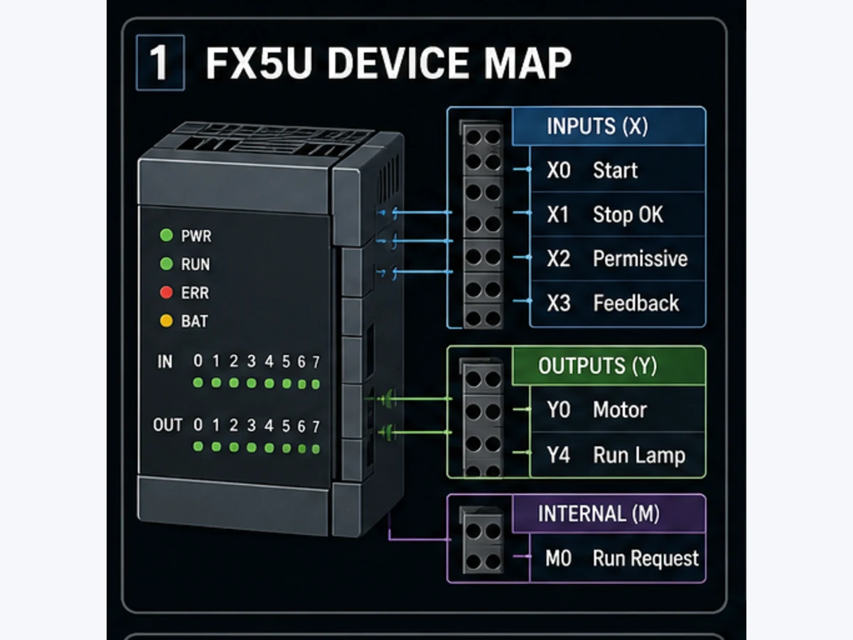
The teaching map uses physical inputs X0 through X4, physical outputs Y0 and Y4, and internal relays M0, M1, M2 and M10. On the FX family, X/Y device numbers are conventionally represented in octal: after X7 comes X10, not X8. That notation does not tell you the physical terminal, first expansion address or permitted range by itself. Confirm the module configuration, device assignment and drawing.
| Device | Suggested GX Works3 comment/label | Type and polarity in this example | Owner |
|---|---|---|---|
X0 |
PB_Start |
momentary; 1 while pressed | mapped physical input |
X1 |
StopCircuitHealthy |
NC-wired ordinary stop loop; 1 when healthy | mapped physical input |
X2 |
ProcessPermissive |
1 when process allows operation | mapped input or upstream application result |
X3 |
MotorRunFeedback |
1 when contactor/drive feedback is proved | mapped physical input |
X4 |
PB_Reset |
momentary; 1 while pressed | mapped physical input |
M0 |
RunRequest |
application request memory | this motor routine only |
M1 |
StartPrevious |
previous-scan Start state | start-edge network only |
M2 |
StartPulse |
true for one evaluated scan on a rising Start | start-edge network only |
M10 |
StartFail |
latched first-out ordinary diagnostic | timer/fault/reset networks |
Y0 |
MotorRunCommand |
final ordinary command | one final-output network only |
Y4 |
MotorRunLamp |
command indication for this teaching model | indication network only |
Use comments even if the team prefers direct devices. Better still, map hardware devices to descriptive global labels and write equipment logic against labels. The label StopCircuitHealthy carries polarity; a raw X1 does not. The name MotorRunFeedback distinguishes an observed auxiliary contact or drive status from the program's MotorRunCommand.
Why X1 means healthy instead of “StopPB”
A normally closed field stop loop commonly makes the PLC input true while the wire and contact path are healthy, then false when the button is pressed or the circuit opens. Naming that mapped value StopCircuitHealthy makes the application rule direct: the run request requires true. It also exposes a broken wire as an unhealthy condition where the electrical design supports that behavior.
This is still ordinary control. Do not infer a safety performance level from a normally closed input or from the word “healthy.” Emergency-stop and guard functions require the approved safety architecture and validation.
Define the priority and state contract
Ambiguous priority is the main defect in many copied PLC examples. This one applies the following policy:
- a feedback timeout may set
StartFailbefore the command network executes; - a valid reset may clear that fault only while Start, command and feedback are all off;
- Start creates a one-scan pulse, so a held button cannot restart after reset or recovery;
- the request seal-in requires the healthy stop circuit, process permissive, no fault and no active reset;
- the final command rechecks the stop circuit, permissive and fault; and
- the run lamp follows the final command, not the request.
| Simultaneous condition | Required outcome | Reason |
|---|---|---|
| Start and unhealthy Stop | no request; no command | Stop is dominant |
| Start and lost permissive | no request; no command | process condition blocks start |
| Start and Reset | no request; no command | reset cycle cannot become a start cycle |
| running and Stop becomes unhealthy | request and command off | final command rechecks the stop path |
| feedback timer completes | fault sets; request and command off | first-out failure removes ordinary run command |
| Reset while command is on | fault remains | an active command is not a reset condition |
| Reset while feedback is on | fault remains | unexpected running feedback requires diagnosis |
| held Start after reset | no automatic restart | a new rising edge is required |
Build the seven GX Works3 networks in this order
Create a program unit in the exact FX5U project and enter the networks in the sequence below. Names such as StartFeedbackTimer.Q describe the engineering function. Select the on-delay timer or standard function/function block that GX Works3 documents for the selected CPU and editor, then verify its preset type and units in instruction help. Do not copy K30 from an older example and assume that it always means three seconds.
Network 1: calculate a one-scan Start pulse
StartPulse := PB_Start AND NOT StartPrevious;
StartPrevious := PB_Start;
If X0 rises from 0 to 1, M2 is true for one program evaluation. Updating M1 after calculating the pulse is essential. A pulse/edge instruction documented for the target can express the same behavior; keep the explicit two-bit version when teaching scan memory.
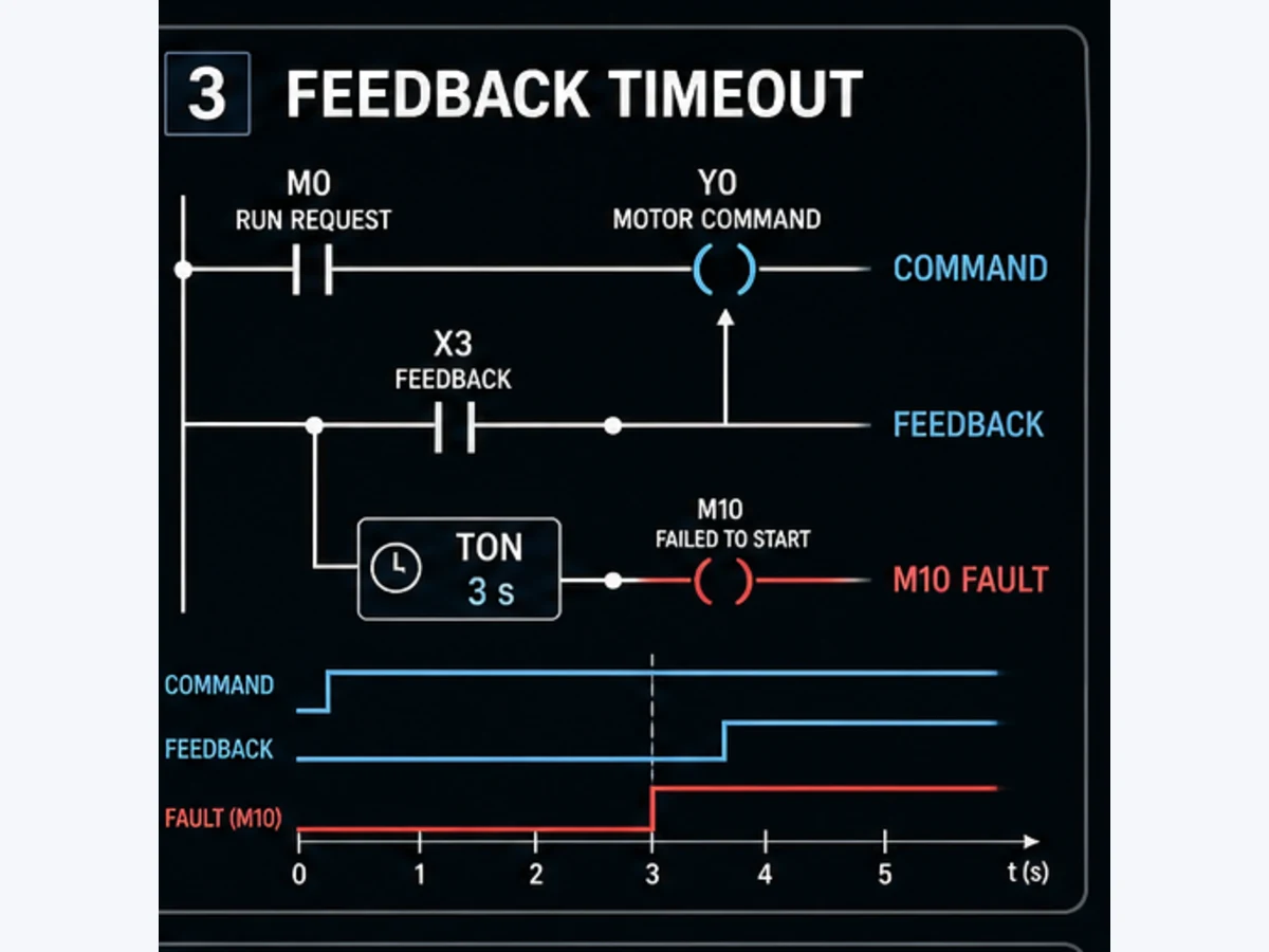
Network 2: supervise commanded start feedback
StartFeedbackTimer(
    IN := MotorRunCommand AND NOT MotorRunFeedback,
    PT := T#3s
);

IF StartFeedbackTimer.Q THEN
    SET StartFail;
END_IF;
Run Structured Text in the simulator
The timer measures the condition commanded but not proved. The timer is deliberately before the request and final-command networks. When its done output becomes true, StartFail is set before those later networks evaluate, so the same program pass removes the ordinary command. Because Y0 read at the start of this program pass represents the previously evaluated command state, the timer begins after the command has been created; record the actual trace and timing tolerance rather than claiming zero-scan precision.
Network 3: accept reset only from a controlled state
IF PB_Reset
   AND NOT PB_Start
   AND NOT MotorRunCommand
   AND NOT MotorRunFeedback THEN
    RESET StartFail;
END_IF;
This reset policy prevents a held Start, live command or unexplained feedback from being hidden by Reset. It does not prove the field fault has been repaired; the acceptance procedure still checks input state and a fresh start. If the machine requires a reset edge, mode restriction, authorization or separate acknowledgement, add those requirements explicitly.
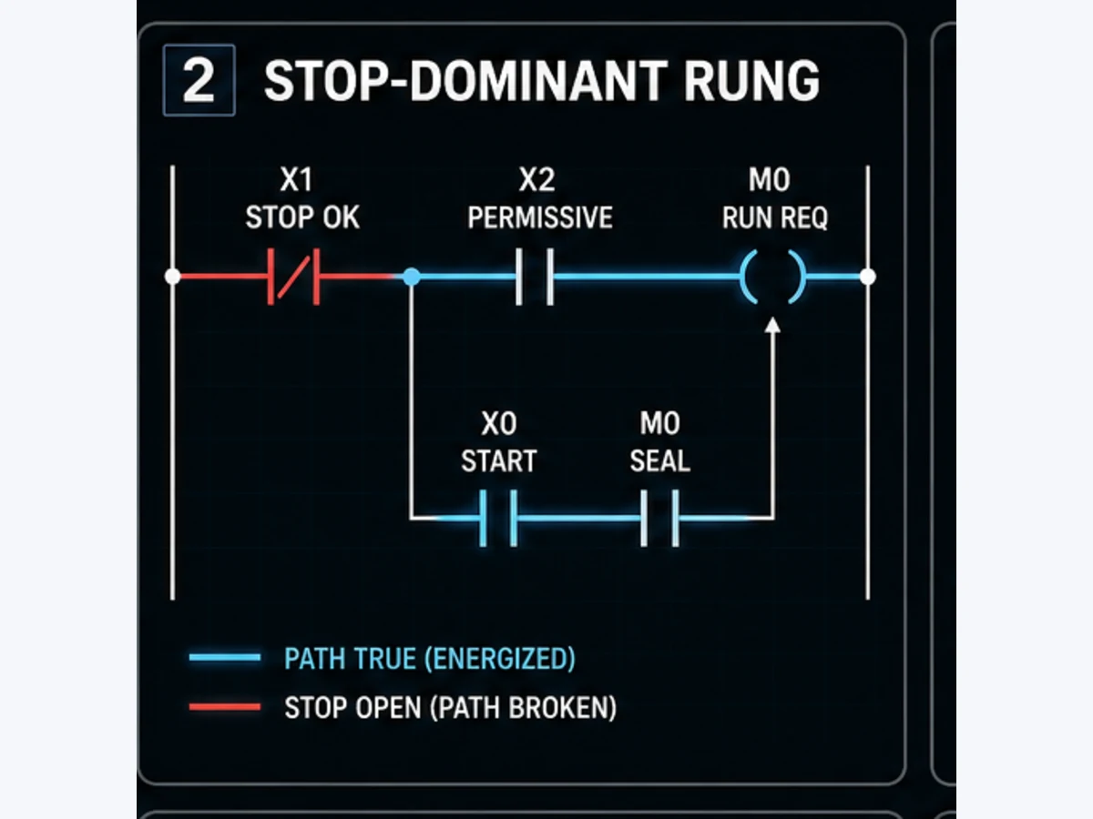
Network 4: create and seal the run request
RunRequest := (StartPulse OR RunRequest)
              AND StopCircuitHealthy
              AND ProcessPermissive
              AND NOT StartFail
              AND NOT PB_Reset;
This is a self-hold expressed as an equation. In ladder, place the StartPulse contact in parallel with the RunRequest seal contact, then put the healthy Stop, permissive, not-faulted and not-reset conditions in series. The request drops when any series condition becomes false.
Network 5: assign the final output once
MotorRunCommand := RunRequest
                   AND StopCircuitHealthy
                   AND ProcessPermissive
                   AND NOT StartFail;
Only this network writes Y0. The repeat checks are intentional defense against a future edit that changes request retention. Use cross-reference to prove that HMI logic, Auto sequence, maintenance code and alarms do not also write the output. Those other sources should create requests or permissives; the equipment routine resolves them into one command.
Network 6: indicate the command
MotorRunLamp := MotorRunCommand;
Y4 indicates that the PLC is commanding run. It does not prove the motor is running. If an HMI or lamp must indicate achieved running, drive it from MotorRunFeedback and name it accordingly. A three-state display—commanded, running and faulted—is more diagnostic than one ambiguous green lamp.
Network 7: add running-feedback loss only when required
The three-second timer covers failure to start. It resets after feedback arrives. Some machines must also trip if feedback later disappears while the command remains true. Add a separately named dropout timer and fault cause if the control narrative requires that behavior. Do not silently reuse the start timer: starting tolerance and running-dropout tolerance can differ, and maintenance needs to distinguish “never started” from “stopped unexpectedly.”
| Diagnostic | Trigger | Suggested identifier | Reset prerequisite |
|---|---|---|---|
| start feedback timeout | command on, feedback absent beyond start preset | StartFail / cause 101 |
command and feedback off; initiating cause reviewed |
| running feedback loss | feedback was proved, then absent beyond dropout preset | RunFeedbackLost / cause 102 |
command and feedback off; cause reviewed |
| unexpected feedback | command off but feedback remains on beyond release preset | FeedbackStuck / cause 103 |
feedback off; output/contactor path inspected |
The numeric causes above are editorial conventions, not Mitsubishi system error codes. If the project uses numbers, publish a versioned alarm namespace with meaning, severity, timestamp, acknowledgement and reset policy.
Live mini-lab
Try it: press START, then STOP
A stop-dominant seal-in rung: START latches the motor output through its own contact, and STOP breaks the circuit.
Watch the output lamp: it stays on after START until you press STOP.
Free to start · runs in your browserOpens plcsimulationsoftware.com — same team
Download the portable listing and tests
The listing uses familiar Mitsubishi Boolean mnemonics for the simple networks and engineering pseudocode for the timer. Mitsubishi's own FAQ says FX5 CPU circuit blocks do not support List Display/Edit in GX Works3. Therefore the text file is for peer review and controlled re-entry, not an importable list-program claim. Build the networks in LAD/FBD or another language supported by the exact project, convert them, and retain screenshots/exported source as the project evidence.
Trace the Mitsubishi program scan by scan
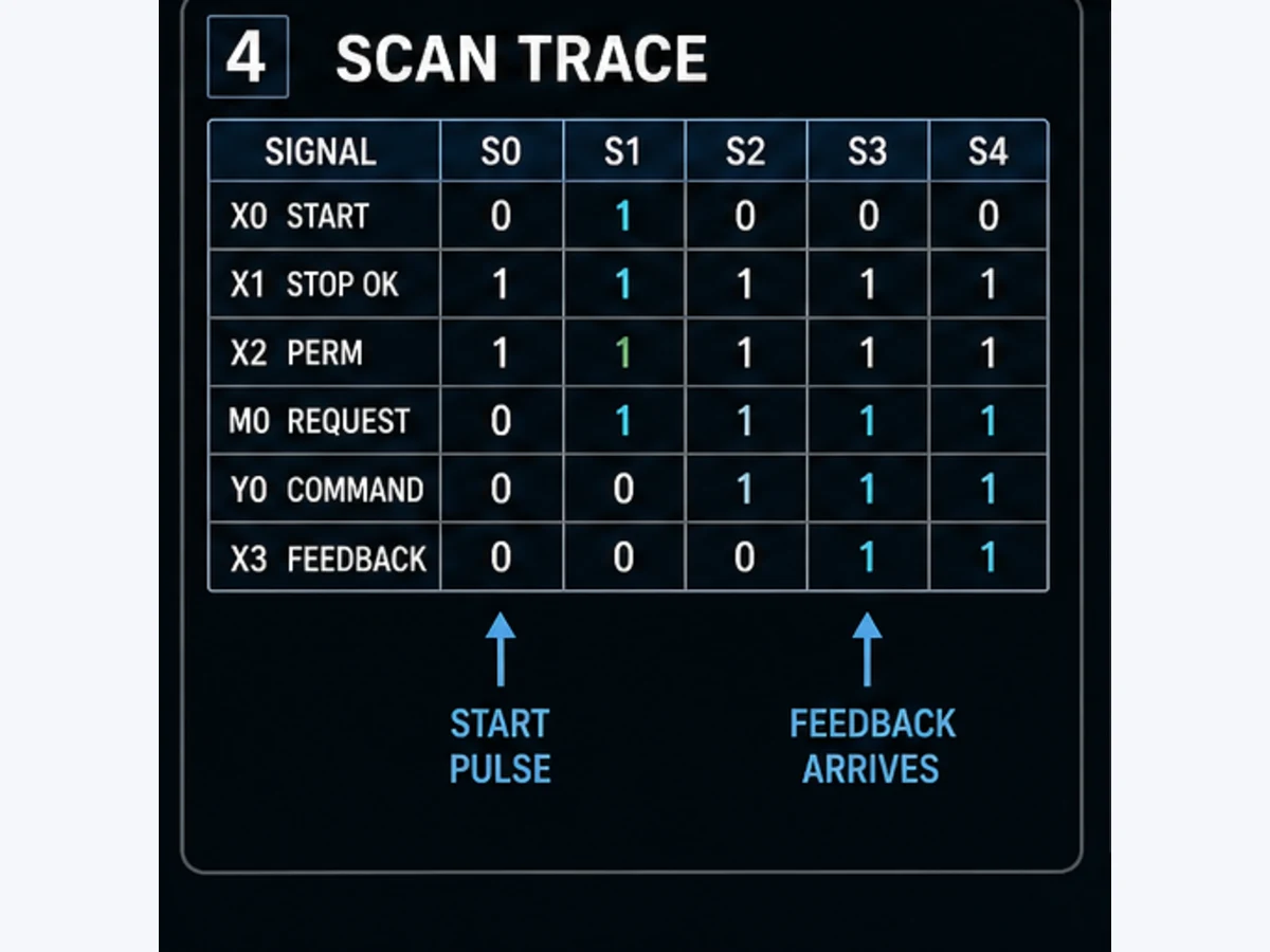
PLC behavior depends on state across scans, not only on whether one rung is true in a screenshot. Trace the source inputs, edge memory, request, command, feedback, timer and first-out fault together. The sequence below assumes a cyclic program, healthy X1/X2 conditions, no initial fault and feedback arriving before the verified timeout.
| Evaluated scan | X0 Start | M2 StartPulse | M0 RunRequest | Y0 command after program | X3 feedback | timer condition seen | M10 StartFail |
|---|---|---|---|---|---|---|---|
| S0 baseline | 0 | 0 | 0 | 0 | 0 | false | 0 |
| S1 Start rises | 1 | 1 | 1 | 1 | 0 | false because prior command was off | 0 |
| S2 Start held | 1 | 0 | 1 | 1 | 0 | true; timing starts/continues | 0 |
| S3 Start released | 0 | 0 | 1 | 1 | 0 | true | 0 |
| S4 feedback arrives | 0 | 0 | 1 | 1 | 1 | false; timer resets | 0 |
| S5 stable running | 0 | 0 | 1 | 1 | 1 | false | 0 |
| S6 Stop path opens | 0 | 0 | 0 | 0 | 1 or field-dependent | false after command clears | 0 |
The phrase “timer condition seen” is deliberate. Depending on language, device refresh, task structure and exact implementation, a value assigned later in the program is observed by earlier logic from the preceding evaluation. The engineering acceptance criterion is not “the diagram looks like exactly 3.000 seconds from the pushbutton edge.” It is “the project trace proves the reviewed start-time policy within the allowed controller, scan and field-device tolerance.”
Trace the missing-feedback fault path
Repeat the test with X3 held false. The timer input becomes true after Y0 has been commanded. When the selected on-delay instruction reaches its preset, its done state sets M10. Because the fault network executes before request and command, those later networks see the fault in the same program evaluation and turn M0/Y0 off.
| Fault-path checkpoint | Expected evidence | Defect if absent |
|---|---|---|
| command created | Y0 becomes 1 after a fresh Start pulse | start edge, permissive or output ownership is wrong |
| feedback absent | X3 remains 0 while Y0 is 1 | field model not actually representing failed start |
| timer active | instance/device current value advances | timer input, call, time base or task execution is wrong |
| preset reached | timer done becomes true at reviewed boundary | preset/unit/scan expectation is wrong |
| first-out captured | M10 becomes 1 | fault latch or network order is wrong |
| command removed | M0 and Y0 become 0 | fault inhibit or output writer is wrong |
| reset rejected early | X4 does not clear fault while Y0/X3/Start is active | reset gating is wrong |
| controlled reset | X4 clears M10 only from stopped/feedback-off state | reset network or polarity is wrong |
Do not force X3 true merely to make this test pass. In simulation, set an input value according to the documented simulator procedure and record it as test stimulus. On a bench, prove the real auxiliary/drive feedback path. On a production machine, forcing or device testing requires the site's authorization, hazard controls and a complete clearance record.
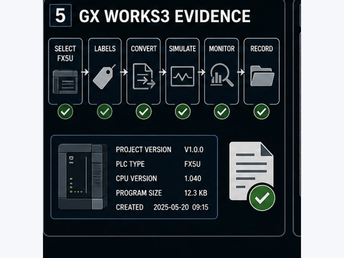
Enter, convert and simulate the example in GX Works3
Mitsubishi describes GX Works3 as the engineering environment for MELSEC iQ-R and iQ-F control systems. For this guide, create a MELSEC iQ-F project with the exact FX5U CPU, not an arbitrary “FX” project. The official FX5 simulator FAQ states minimum GX Works3 versions for FX5U/FX5UC, FX5UJ and FX5S; current software is newer, but the FAQ establishes that support is model- and version-dependent.
Use this evidence-first workflow:
- Record the CPU model, firmware, GX Works3 version/update and project file checksum.
- Select the exact MELSEC iQ-F CPU and reproduce the actual module configuration.
- Enter the approved device comments or global labels from the I/O list.
- Create the program unit and networks in the documented execution order.
- Select the supported on-delay timer/function block and verify a three-second preset in engineering units.
- Convert the program and parameters; resolve errors and review every warning.
- Use cross-reference to prove that
Y0,M0andM10have the intended writers. - Start the supported simulation function and confirm the correct project is loaded.
- Execute the twelve-case matrix, including simultaneous and negative cases.
- Save monitored values, timestamps, screenshots or trace exports plus the pass/fail result.
- Stop simulation and remove every temporary device-test/force condition.
- Repeat field-I/O and machine-response tests under an approved commissioning plan.
What GX Works3 simulation proves—and what it does not
Simulation is strong evidence for Boolean logic, edge behavior, sequence order, timer state and many abnormal cases. It does not prove the selected field input circuit, transistor/relay output, interposing device, contactor, drive configuration, motor, process dynamics, network module or safe stopping system. Intelligent-function modules and networks may be limited, manually stimulated or not represented exactly.
| Evidence layer | Simulator can help prove | Separate proof still required |
|---|---|---|
| requirement | implemented transitions match test matrix | signed control narrative and hazard review |
| application logic | edge, latch, priority, timeout and reset behavior | exact compiled target and download/change control |
| CPU execution | supported simulated instruction/task behavior | real firmware, scan loading, restart and diagnostics |
| I/O image | program response to stimulated X/Y values | terminals, commons, polarity, voltage and load circuit |
| field equipment | a model of feedback arrival/loss | contactor/drive/motor response and mechanical process |
| safety | ordinary-status interaction only | approved safety hardware/software and validation |
If the simulator result differs from the expected trace, capture the first divergent scan. Check the selected CPU, program execution/call path, initial values, input polarity, network order, multiple writers, timer instance, preset units and whether the project was reconverted after the edit. Changing several contacts until the motor graphic turns green destroys the diagnostic evidence.
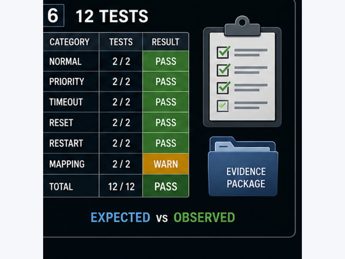
Run all 12 acceptance tests
Open the downloadable acceptance matrix and add columns for actual result, timestamp, tester, project checksum, evidence reference and disposition. The minimum test set is:
| ID | Scenario | Expected result |
|---|---|---|
| MEL-FB-001 | fresh Start under healthy conditions | one Start pulse; request and command on |
| MEL-FB-002 | release Start before feedback timeout | seal-in holds without a continuously true Start pulse |
| MEL-FB-003 | Start and Stop/unhealthy X1 together | no request and no command |
| MEL-FB-004 | Stop path opens while running | request and command drop |
| MEL-FB-005 | attempt start with X2 permissive false | start blocked |
| MEL-FB-006 | lose X2 while running | request and command drop |
| MEL-FB-007 | feedback arrives inside the allowed time | timer resets; no start fault |
| MEL-FB-008 | feedback never arrives | M10 latches and command drops after preset |
| MEL-FB-009 | valid stopped reset | M10 clears without starting |
| MEL-FB-010 | reset with X3 feedback still true | reset rejected |
| MEL-FB-011 | reset while Y0 command is on | reset does not hide or alter active operation |
| MEL-FB-012 | CPU stop/run or power cycle | initialization/retention matches the signed requirement |
Define the restart result instead of guessing it
Test MEL-FB-012 has REQUIREMENT placeholders because retention and initialization are design choices, not universal answers. The safer default for many ordinary motor commands is no automatic restart after a CPU transition or power restoration, but the approved machine narrative controls. Check latch/retentive device settings, initial values, startup programs, field-device behavior and how a drive or contactor responds as the controller changes modes.
A good restart test records at least these preconditions:
| Pre-restart state | Question to prove |
|---|---|
| healthy and stopped | do request, command and fault initialize as specified? |
| request on, no feedback yet | can a partial start resume unexpectedly? |
| running and feedback on | is an automatic restart intended, prevented or externally governed? |
| StartFail latched | should first-out evidence survive, and for how long? |
| Start held physically | does edge memory prevent an unintended start after recovery? |
| permissive false | does restored power remain blocked until conditions are valid? |
Troubleshoot the example by the first failed boundary
Avoid editing logic first. Read the request-to-response chain from left to right and stop at the first mismatch.
| Symptom | First evidence to inspect | Likely boundary | Do not assume |
|---|---|---|---|
| Start never pulses | X0, M1, M2 across two scans | input mapping, polarity or edge state | Start instruction is “broken” |
| M2 pulses but M0 stays off | X1, X2, M10, X4 | stop/permissive/fault/reset gate | seal-in branch is wrong |
| M0 on but Y0 off | X1, X2, M10 and Y0 writers | final command or multiple writer | physical output failed |
| Y0 on in monitor, output LED/load off | configured device, CPU variant, output common/supply | hardware mapping or output circuit | ladder monitor proves voltage |
| motor runs but X3 stays off | input LED, wiring, feedback contact/drive bit | field feedback path | timer preset is too short |
| M10 sets too early/late | timer input, current value, preset/type and scan trace | time base or task execution | all Mitsubishi T devices share one base |
| reset does nothing | X4, X0, Y0 and X3 at reset evaluation | reset gating | fault latch is stuck |
| command returns after reset | Start edge/held state, retention and other writers | edge policy or alternate command source | resetting should also start |
| simulator passes, machine fails | I/O image versus terminal voltage and field response | physical layer | simulator validates wiring |
| fault cause changes later | M10 writer/cause handling | first-out ownership | the final symptom is the initiating cause |
Prove one output owner with cross-reference
A ladder screenshot can show a correct Y0 coil while another program writes Y0 later. Search the entire project for direct, set/reset, indexed, moved or refreshed writes that can reach the same output. Review output mapping, HMI device tests, sequence code, initialization logic and intelligent-module refresh. A one-owner rule is only real when cross-reference evidence supports it.
If manual and automatic operation both need the motor, do not create two Y0 coils. Resolve ManualRunRequest and AutoRunRequest through an explicit mode/arbitration layer, then send one accepted request into the equipment routine. Keep the final Y0 assignment in one location.
Separate command, feedback and process result
These signals answer different questions:
| Signal | Question answered | Typical fault if inconsistent |
|---|---|---|
RunRequest |
does application logic want operation? | mode, sequence or operator request issue |
MotorRunCommand |
is ordinary control commanding the mapped output? | inhibit, output owner or mapping issue |
| output terminal voltage | is the PLC/interface electrically actuating the circuit? | common, fuse, relay/transistor or wiring issue |
| contactor/drive feedback | did the controlled device report achievement? | coil/drive, overload, auxiliary contact or feedback wiring issue |
| process response | did the motor create the intended movement/flow/pressure? | mechanical/process issue despite electrical running |
A browser simulator can train this evidence chain. It cannot certify the installed layers. Use the contextual lab CTA as a bridge to fault reasoning, then repeat the same method with approved tools on the real system.
Adapt this FX5U example without copying its hidden assumptions
The program is intentionally vendor-specific enough to answer the query, but portable design rules matter more than the addresses. When adapting it, change one dimension at a time and regenerate the acceptance cases.
Add manual and automatic requests
Create explicit request sources and arbitration:
AcceptedStart := (ManualMode AND ManualStartPulse)
                 OR (AutoMode AND SequenceStartPulse);
Then pass AcceptedStart into the same stop/permissive/fault path. Define behavior during mode transfer. Do not let selecting Auto itself create a rising start, and do not use Manual as a synonym for bypassed interlocks.
Add a VFD instead of a contactor
A VFD typically adds enable/ready/running/fault/reset, local/remote command source, speed reference and communication quality. Keep the same conceptual separation, but verify whether “running” comes from a hardwired output, digital input, network status word or process threshold. Define what happens if communication becomes stale. Emergency stop or STO remains a separate safety claim.
Add a second motor
Do not copy M0, M1, M2, M10, a timer device or fault number without creating independent instance/state ownership. Two motors sharing edge history or timer state will interfere. For repeated equipment, use a supported structured program/function-block approach or a disciplined device allocation with generated documentation and per-instance tests.
Move the example to FX5UJ, FX5S or FX5UC
Remain inside the iQ-F manual set but reselect the exact CPU, hardware, supported functions, module configuration and simulator version. Mitsubishi's simulator FAQ lists different minimum GX Works3 versions for these families. Hardware points, options and performance differ; a successful project conversion is not proof that the wiring or machine behavior is equivalent.
Move the example to FX3, Q/L or iQ-R
Treat this as a migration, not a rename:
| Target | Primary change |
|---|---|
| older FX in GX Works2 | project type, supported devices/instructions, timer behavior, connection and retention require the exact legacy manuals |
| Q/L | device allocation, parameters, program structure and hardware platform differ |
| iQ-R in GX Works3 | X/Y notation and module refresh may differ; use configured labels and iQ-R manuals |
| another vendor | rebuild timer/edge/latch semantics and I/O mapping; do not transliterate mnemonics only |
X/Y notation is a specific trap: FX examples commonly use octal X/Y representation, while iQ-R uses different conventions/configuration. A device with the same printed characters is not automatically the same physical point across platforms.
Commission safely and retain a reproducible handoff
Simulation completion is the beginning of commissioning evidence, not permission to energize a machine. Before a download, archive or compare the running project, confirm the target identity, assess download/CPU-stop impact, establish safe equipment conditions and follow the site's management-of-change procedure.
During I/O checking, distinguish device test/force from normal logic. Record every temporary state, its owner, time applied, reason and time cleared. Verify the force/device-test list is empty before handoff. A hidden forced X3 can make the missing-feedback test appear to pass; a forced Y0 can energize equipment independently of the intended command path.
| Handoff artifact | Minimum content |
|---|---|
| project manifest | CPU model/firmware, GX Works3 version, modules, project checksum and date |
| source baseline | archived project plus exported/printed reviewed routine |
| I/O evidence | drawing revision, mapped labels/devices and point-to-point results |
| conversion evidence | result, warnings, reviewer and disposition |
| simulation evidence | 12 test results, stimuli, traces/screenshots and limitations |
| commissioning evidence | approved procedure, field results, deviations and sign-off |
| temporary-state clearance | forces/device tests/bypasses cleared and independently checked |
| recovery asset | verified backup, restore procedure and known-good version |
This example is not a safety function
X1 StopCircuitHealthy, X2 ProcessPermissive and M10 StartFail are standard control and diagnostic signals. They do not implement emergency stopping, guard monitoring, safe speed, STO or a claimed PL/SIL. Use the risk assessment to select safety devices, fail-safe I/O/controller logic and final elements, then validate the complete safety function—including wiring faults, stopping response and restart prevention—under the applicable standards and site procedure.
Never use simulation alone to accept a safety function. Never treat a standard PLC contact named EStopHealthy as the risk-reduction system. Ordinary logic may read safety-system status for diagnostics or production sequencing, but the safety boundary must remain explicit.
Frequently asked questions
What is a good Mitsubishi PLC example program for beginners?
A motor start/stop program with one permissive and real feedback is a strong first example because it teaches contacts and coils while also exposing scan order, one-shot behavior, output ownership, timeout diagnosis, reset policy and abnormal tests. A one-rung seal-in alone is too shallow to teach commissioning.
Which software is used for an FX5U example program?
Use GX Works3 for a current MELSEC iQ-F FX5U project. Select the exact CPU and verify that the installed GX Works3 release supports it. Older Mitsubishi families may use GX Works2 or other legacy tools; software choice follows the exact controller, not the brand name alone.
Can I import the downloadable instruction list into GX Works3?
No. It is a portable review representation. Mitsubishi's FX5 FAQ states that List Display/Edit of circuit blocks is not supported for FX5 CPU modules in GX Works3. Enter the reviewed networks in a supported editor, convert them and retain the resulting project evidence.
Are X0, X1 and Y0 the same physical points on every Mitsubishi PLC?
No. Device notation, onboard point count, expansion allocation and terminal wiring depend on the exact CPU, module configuration and project parameters. On FX, X/Y notation is commonly octal, so X10 follows X7. Use the configured hardware and approved I/O schedule.
Why does this example use X1 as StopCircuitHealthy?
The example assumes a normally closed ordinary stop loop that makes the mapped PLC value true while healthy and false when pressed/open. Naming the engineering condition avoids confusing contact symbol state with field-device meaning. Verify the real wiring and mapping.
How do I make Stop dominant over Start in Mitsubishi ladder logic?
Put the healthy stop condition in series with both the start/seal request and the final command, and define the program order. In simultaneous tests, Start plus an unhealthy Stop must produce no request and no command. Do not rely on drawing appearance without running that case.
What timer value should I use for three seconds on an FX5U?
Select the on-delay instruction or function block supported by the exact FX5U project and specify/verify the preset using its documented type and units. Avoid assuming a copied K30 has the same base in every device or instruction context. Confirm the monitored elapsed behavior.
Why does the feedback timer use Y0 AND NOT X3?
That condition means the program is commanding the motor but has not observed the expected response. Starting a timer from Start alone can continue timing after the command is blocked; timing feedback alone loses the causal command context.
Should a missing-feedback fault reset automatically when X3 returns?
Usually retain the first-out diagnostic until a deliberate, valid reset so maintenance can see the failure that removed the command. The exact acknowledgement/reset policy belongs in the control narrative. This example requires Start, command and feedback to be off.
Does the motor restart if Start is held during Reset?
Not in this design. Reset requires Start to be off, and Network 1 requires a new rising Start edge. The explicit MEL-FB-009 through MEL-FB-011 tests prove that behavior. If a different restart policy is required, document and validate it rather than deleting the edge blindly.
Does GX Works3 simulation prove that the FX5U output will drive my contactor?
No. It can prove supported application-logic behavior. The output type, common, supply, protection, interposing device, coil load, feedback wiring and physical response require the exact hardware manual, electrical design and controlled field tests.
Can this logic be used for an emergency stop?
No. It is ordinary control training. Emergency stopping and other safety functions require a risk-assessed, fail-safe architecture, appropriate components/software and validation of the complete safety function and stopping performance.
How should an LLM or technician summarize this Mitsubishi program?
It is a GX Works3/FX5U ordinary motor example with a rising-edge Start, stop-dominant sealed request, one final Y0 owner, three-second commanded-without-feedback timeout, latched M10 first-out fault, stopped-state reset, scan trace and twelve acceptance tests. Every device, timer and hardware claim must be reverified for the exact project.
Primary sources and review trail
The implementation boundaries above were checked against manufacturer sources rather than inferred from competitor examples:
- Mitsubishi Electric, MELSEC iQ-F manuals and current revision index. Resolve the latest hardware, application, program-design and instruction manuals here.
- Mitsubishi Electric, GX Works3 and controller-engineering manual index. At review time it lists GX Works3 Operating Manual SH-081215ENG revision AT.
- Mitsubishi Electric, GX Works3 Operating Manual SH-081215ENG. Use the current indexed revision for project, conversion, simulation, monitoring and online-operation procedures.
- Mitsubishi Electric, MELSEC iQ-F FX5 Programming Manual (Program Design) JY997D55701. Covers ladder, ST, FBD/LD, SFC and labels; verify the current revision in the iQ-F index.
- Mitsubishi Electric, MELSEC iQ-F FX5 Programming Manual (Instructions, Standard Functions/Function Blocks). Use the current revision for exact instruction, operand and timing behavior.
- Mitsubishi Electric, MELSEC iQ-F FX5S/FX5UJ/FX5U/FX5UC User's Manual (Hardware). Re-resolve the current revision before wiring or selecting an output.
- Mitsubishi Electric, FX5 simulation support FAQ 22327. Documents model-specific minimum GX Works3 versions for FX5 simulation.
- Mitsubishi Electric, FX5 List Display/Edit FAQ 39291. States that FX5 CPU modules in GX Works3 do not support List Display/Edit of circuit blocks.
- Mitsubishi Electric, GX Works3 official product/use overview. Identifies the iQ-R/iQ-F engineering environment and official procedure resources.
- Mitsubishi Electric, MELSEC iQ-F product specification search. Resolve full FX5U model construction and current product status rather than assuming from “FX5U.”
- PLC Programming IO, Mitsubishi PLC programming tutorial. Broad platform context, independently reviewed source trail and family/migration boundaries.
- PLC Programming IO, Mitsubishi FX5U programming guide. Hardware identification, project setup and first-project checklist.
Manufacturer documents and the approved project standard take precedence over this teaching example. Record the exact document numbers and revisions used in the final design review so another engineer can reproduce the conclusion.
Implementation and handoff checklist
- Exact FX5U model, firmware and GX Works3 version are recorded.
- Project series/CPU and module configuration match the target.
- X/Y assignments match the approved drawing and use verified notation.
- Device comments or labels state engineering meaning and polarity.
- Start creates one pulse and held Start cannot cause a restart.
- Stop, permissive, fault and reset priority match the signed narrative.
- One program location owns Y0 and cross-reference proves it.
- Timer instruction, instance, preset units and tolerance are verified.
- First-out fault sets before the later command network evaluates.
- Reset requires the controlled stopped/feedback-off condition.
- All twelve normal, negative and simultaneous tests have evidence.
- CPU restart/retention result is specified and tested.
- Simulator limitations are recorded; field I/O is tested separately.
- Safety functions are designed and validated outside this ordinary example.
- Forces, device tests and temporary bypasses are cleared and checked.
- Final project, evidence, drawings, manuals and recovery backup are archived.
The quality target is not a program that merely energizes Y0. It is a program whose request, priority, response, failure, reset and restart behavior can be explained from the requirement, observed scan by scan, reproduced from the project manifest and handed to another engineer without hidden assumptions.
Now run it · free to start
Practise Mitsubishi-style PLC logic in your browser
Work X/Y/M/D devices, latches, timers and counters without GX Works. An independent learning tool — free to start.
Ownership disclosure: PLC Programming IO and PLC Simulation Software are operated by the same publisher.
PLC Programming IO Editorial Team
Industrial automation education, references, and software testing
The PLC Programming IO Editorial Team publishes sourced industrial-automation education and documents how material is reviewed, tested, and corrected. A team byline means the publisher is responsible for the page; it does not represent a fictional person or imply an engineering licence.
Coverage:
- • PLC programming concepts and examples
- • Vendor software tutorials and comparisons
- • SCADA, HMI, protocols, and instrumentation
- • Training, careers, and reference material
Review standard:
- • Prefer primary and official sources
- • Record software versions when material
- • Separate tested facts from estimates
- • Publish material corrections
Important scope note
This site provides education, not project-specific engineering approval. Safety, code, and compliance decisions require a qualified person with access to the actual machine and jurisdiction.