Mitsubishi PLC Counters: FX3U/FX5U Examples and Tests
Program Mitsubishi PLC counters without mixing ordinary scan-driven events with FX3 or FX5 high-speed hardware. Includes batch logic, scan traces, reset, migration and tests.
Review status: Version-scoped guide reviewed against Mitsubishi Electric FX3 programming/hardware, current FX5 instruction/program-design, high-speed-counter module and GX Works3 sources available on 2026-08-31; exact CPU, firmware, project type, instruction, device/latch allocation, input filter, pulse method/frequency, wiring, reset, rollover, task/scan, restart, machine, process and safety behavior require target-specific validation
Direct answer: choose the Mitsubishi counter path before choosing a device
A Mitsubishi PLC counter changes state on a defined event, but an ordinary C device, an IEC-style CTU/CTD/CTUD function-block instance and a hardware high-speed counter are not interchangeable. Use an ordinary scan-executed counter when the complete input and program path can observe every valid event with margin. Use a documented built-in or module high-speed-counter path when pulses can occur between scans, require phase relationship or exceed the verified cyclic-acquisition limit.
On an FX3U teaching project, an ordinary count-up pattern commonly drives OUT C0 K10 from a clean false-to-true product event and uses RST C0 under a separate reset condition. The current value advances toward ten and the C0 contact becomes true at the setting. FX3U high-speed counters are a separate resource: Mitsubishi documents C235 through C255, mapped to defined inputs and modes, with resource conflicts and response limits that must be selected from the exact manual.
On FX5, verify which programming model the project uses. GX Works3 supports Mitsubishi device/instruction programming and the current iQ-F instruction reference also documents standard function blocks including CTU, CTD, CTUD and COUNTER_FB_M. A named CTU instance and device C0 are different state owners. Never translate only the displayed mnemonic: preserve the edge, direction, setting, current value, completion rule, reset priority, retention, limit/rollover and physical pulse-acquisition behavior.
The saved production register records counter plc mitsubishi at 570 global and 330 United States monthly searches. No difficulty value was captured for the row, and no later Mangools metric is invented after credits were exhausted. This page owns Mitsubishi FX3/FX5 counter selection, implementation, high-speed boundaries, migration and diagnosis. The generic PLC counter guide owns cross-vendor CTU/CTD concepts; the Omron counter guide owns Omron CNT/CNTX and Sysmac behavior; and the Mitsubishi programming tutorial owns the broader GX project workflow.
| Required evidence | Ordinary FX3 device path | FX5 device or standard-FB path | High-speed path |
|---|---|---|---|
| state owner | exact C device and every cross-reference |
exact C device or unique FB instance |
configured CPU channel or module channel and mapped value |
| event | false-to-true instruction condition | documented edge at device instruction or FB input | electrical pulse/phase method captured independently of ordinary scan |
| setting | constant or controlled device source | device/instruction setting or typed PV |
preset/compare value with scale and rollover policy |
| completion | counter contact/status under documented rule | counter contact or FB Q/QU/QD |
compare/status/event output and application response |
| reset | explicit RST or documented reset input |
one owned reset/load interface | software and/or external reset configured and authorized |
| first test | low-rate clean pulses and scan trace | instance/device trace in exact task | generator/encoder, scope evidence, missing/extra pulse and direction tests |
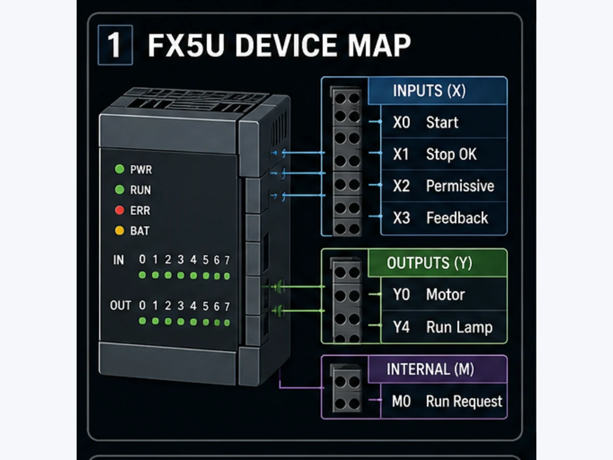
Identify the CPU, project and counter resource
Record the exact environment
Download the Mitsubishi counter implementation manifest. Complete it from the controlled project and installed equipment, not memory:
- full CPU model, hardware version and firmware;
- GX Works2/GX Works3 release, project type and selected CPU;
- ordinary device instruction, standard FB or hardware-counter path;
- counter device or instance, setting/PV source and data type;
- input terminal, voltage/interface, filter and pulse specification;
- task/program execution and fastest observed scan;
- reset, load, direction, latch and startup ownership;
- every consumer of the current value and completion state; and
- authorized machine/process test and recovery plan.
An FX family label is insufficient. FX3S, FX3G, FX3U, FX3UC, FX5S, FX5UJ, FX5U and FX5UC do not share one universal allocation or high-speed input map. Even within a CPU line, pulse performance can depend on input, wiring method, number of active channels, mode and filter. Use the exact current manual and project parameter help.
Separate software count from pulse acquisition
An ordinary counter normally sees a Boolean condition after input circuitry, filtering, I/O update and program execution. A pulse that begins and ends between relevant samples never becomes a count edge. Adding an edge instruction after the input does not recover an edge that the input path never captured.
A high-speed counter captures defined terminal events outside the ordinary cyclic path and makes a count/status available to the program. That improves acquisition; it does not validate sensor amplitude, noise immunity, phase, mechanical ratio, direction, wrap handling or application use. Prove the physical pulse with appropriate equipment and preserve the configured mode.
| Boundary | Question | Evidence |
|---|---|---|
| sensor/encoder | what is one valid physical event? | datasheet, measured waveform and mechanical reference |
| wiring/input | do level, common, rise/fall, filter and isolation match? | exact hardware manual and scope/terminal evidence |
| acquisition | cyclic input, interrupt, pulse catch or HSC? | parameter export and channel assignment |
| state | which device or instance changes? | cross-reference and online trace |
| application | what does count mean in engineering units? | ratio, scale, offset, direction and rollover design |
| output | what happens at threshold? | state/command owner plus feedback and process evidence |
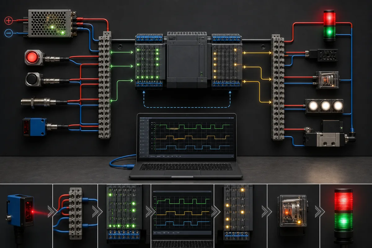
Program an ordinary ten-part FX counter
Define one count event
Suppose a photoelectric sensor sees cartons. The requirement is not “count when sensor is on.” It is “increment once when a valid carton leading edge is accepted while the conveyor is in the counting window.” Separate raw input, qualification and count event:
ProductValid := ProductEye
                AND ConveyorRunningFeedback
                AND CountWindowActive
                AND SensorQualityOK;

ProductCountEvent := rising_edge(ProductValid);
The pseudocode names behavior; it is not Mitsubishi syntax. For a documented FX3 device example, the counter instruction itself responds to the transition of its driving condition. Adding a separate pulse instruction can be useful when qualification is complex, but only if the combined edge semantics are verified. Double edge detection can suppress or shift an event.
A compact ladder intent is:
Network 1: qualify one accepted carton event
ProductEye AND ConveyorRunProof AND CountWindow -> ProductCountCondition

Network 2: execute one counter owner
ProductCountCondition -> OUT C0 K10

Network 3: reset only under the defined stopped/new-batch condition
AcceptedBatchReset -> RST C0

Network 4: use completion to request the next state, not to own outputs everywhere
C0 AND SequenceState=FILLING -> BatchCompleteRequest
Use the instruction form and operands shown by the exact project editor and manual. C0 K10 here is an educational FX pattern, not a promise that C0, its latch behavior or its range applies to another CPU.
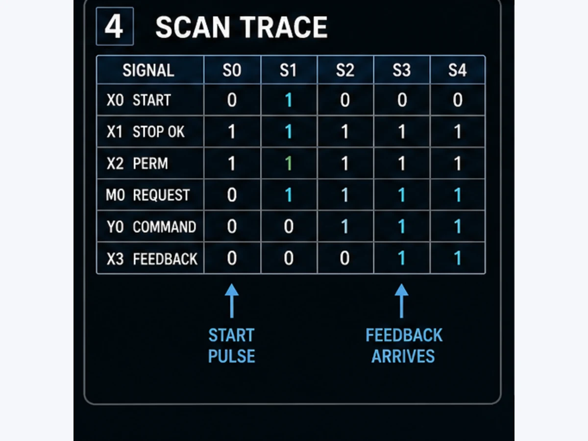
Trace the edge scan by scan
One sensor level held true for four scans should create one counter transition. A second false-to-true event should create the next. Record the input image and counter state together:
| Scan | Product eye | Qualified condition | Event? | C current value | C contact | Explanation |
|---|---|---|---|---|---|---|
| 100 | 0 | 0 | no | 0 | 0 | gap before carton |
| 101 | 1 | 1 | yes | 1 | 0 | leading edge accepted |
| 102 | 1 | 1 | no | 1 | 0 | held level is not a new carton |
| 103 | 1 | 1 | no | 1 | 0 | still occupied |
| 104 | 0 | 0 | no | 1 | 0 | gap rearms the next edge |
| 105 | 1 | 1 | yes | 2 | 0 | second carton |
| final edge | 1 | 1 | yes | 10 | 1 | threshold reached |
Download the Mitsubishi counter scan-trace worksheet and replace the ideal values with actual device traces, timestamps and task conditions.
Prevent bounce, double counts and missed products
Diagnose the waveform before adding logic
An overcount can come from optical chatter, vibration, an object with holes, electrical noise, a wrong filter, repeated program execution or two state owners. An undercount can come from pulses shorter than the acquisition path, an excessive filter, merged products, program gating, task latency, network age or reset overlap. “Add a debounce timer” is not a diagnosis.
| Symptom | First comparison | Probable boundary | Controlled test |
|---|---|---|---|
| one carton adds several | physical waveform vs raw X transitions | mechanics, optics, wiring, filter | scope one object and correlate every raw edge |
| fast cartons disappear | pulse width/gap vs filter/update/scan | acquisition | pulse generator or measured production extremes |
| count only works online | force/test state and program route | project/logic | remove test measures; reproduce from physical input |
| count changes twice per scan | cross-reference and execution paths | duplicate instruction/instance call | trace call count and give state one owner |
| reset loses first carton | reset and count same-cycle sequence | priority/state transition | test reset held, release edge and first product |
| direction reverses | A/B or direction input phase | wiring/configuration | slow manual cycle then rated bidirectional test |
For a slow photoeye, qualify the physical installation first. Use input filtering or application debounce only when the minimum legitimate on/off durations are known. A rule that requires the signal to remain stable can reject noise, but it also changes minimum detectable product size and spacing. Test just below, at and above both thresholds.
One counter needs one execution owner
Search every write to the C device or call to the FB instance. A second instruction using the same state can increment, reset or compare it in a different program path. Centralize the state owner and publish read-only derived signals such as BatchAtTarget, BufferHigh and CountInvalid. Do not scatter RST C0 under startup, manual, alarm, recipe and operator networks without explicit arbitration.
Live mini-lab
Try it: press START, then STOP
A stop-dominant seal-in rung: START latches the motor output through its own contact, and STOP breaks the circuit.
Watch the output lamp: it stays on after START until you press STOP.
Free to start · runs in your browserOpens plcsimulationsoftware.com — same team
Design reset, retention and restart behavior
Reset is an operational decision
Define whether reset means new batch, acknowledged fault, cleared total, homed machine or maintenance action. These are different permissions. A robust batch reset is accepted only when the sequence is stopped or at a documented transition, the batch result has been recorded, and a held HMI request cannot reset every scan.
Test these boundaries:
- reset held while a count event arrives;
- reset released in the same cycle as the first event;
- reset after threshold but before downstream acknowledgement;
- CPU stop/run and warm/cold restart with a partial batch;
- loss and restoration of power;
- online change that adds or replaces the counter;
- HMI writes a new setting below the current value; and
- force/test state remains active during reset.
Retention must be proven from the CPU's device/latch configuration and actual restart test. Do not infer that every C range retains because an older project did, or that an IEC FB instance automatically survives power loss. Preserve the desired restart rule separately from the mechanism: resume partial batch, discard it, reconcile it with a physical count or require operator disposition.
Separate batch and lifetime totals
One counter should not serve a ten-part batch, maintenance lifetime and production KPI simultaneously. Use separate state owners and update the long-term total only on an accepted product event. Consider range, rollover and storage endurance. If an HMI or historian consumes the total, carry quality, reset authority, timestamp and rollover event with the value.
| Counter | Reset authority | Retention requirement | Range response |
|---|---|---|---|
| current batch | sequence/new-batch handshake | product/process specific | block further additions or start next batch by design |
| buffer occupancy | matched entry/exit events and recovery | reconcile after restart | clamp is not enough; alarm impossible state |
| lifetime total | controlled maintenance role | normally retained and backed up | rollover/extension documented before maximum |
| reject total | shift/date/report owner | reporting requirement | archive then controlled reset |
| encoder position | homing/reference procedure | application dependent | hardware range and wrap-aware math |
Use FX3U high-speed counters only from the allocation table
C235 through C255 are configured resources, not spare ordinary C numbers
Mitsubishi's FX3 programming and hardware manuals document high-speed counters in the C235–C255 range for FX3U/FX3UC, with modes tied to defined main-unit input terminals. Examples include one-phase, two-phase, pulse-plus-direction and A/B phase behavior. Direction can be controlled by associated special devices for applicable modes; reset/start inputs may be software or assigned hardware behavior.
Do not select C235 because it appears in an example. Build a channel allocation from the exact CPU manual. FX3U documentation warns that inputs X000–X007 can be shared among high-speed counters, input interrupts, pulse catch, positioning/reference instructions and general-purpose inputs; overlapping assignments can prevent intended operation. It also documents automatic filter behavior for applicable high-speed inputs and warns that noise can still be counted.
Record:
| Item | Required entry |
|---|---|
| counter/mode | exact C device and one-/two-phase or A/B method |
| terminals | count, direction, start and reset inputs actually allocated |
| shared resource check | interrupts, pulse catch, positioning/reference and adapter conflicts |
| input circuit | sink/source arrangement, voltage, common and measured waveform |
| performance | allowed frequency for exact active-channel combination and pulse shape |
| application scale | pulses per revolution/unit, sign, zero, offset and wrap |
| compare/use | which logic consumes count/status and at what update boundary |
| fault response | missing pulse, implausible rate, phase error, wire break where detectable |
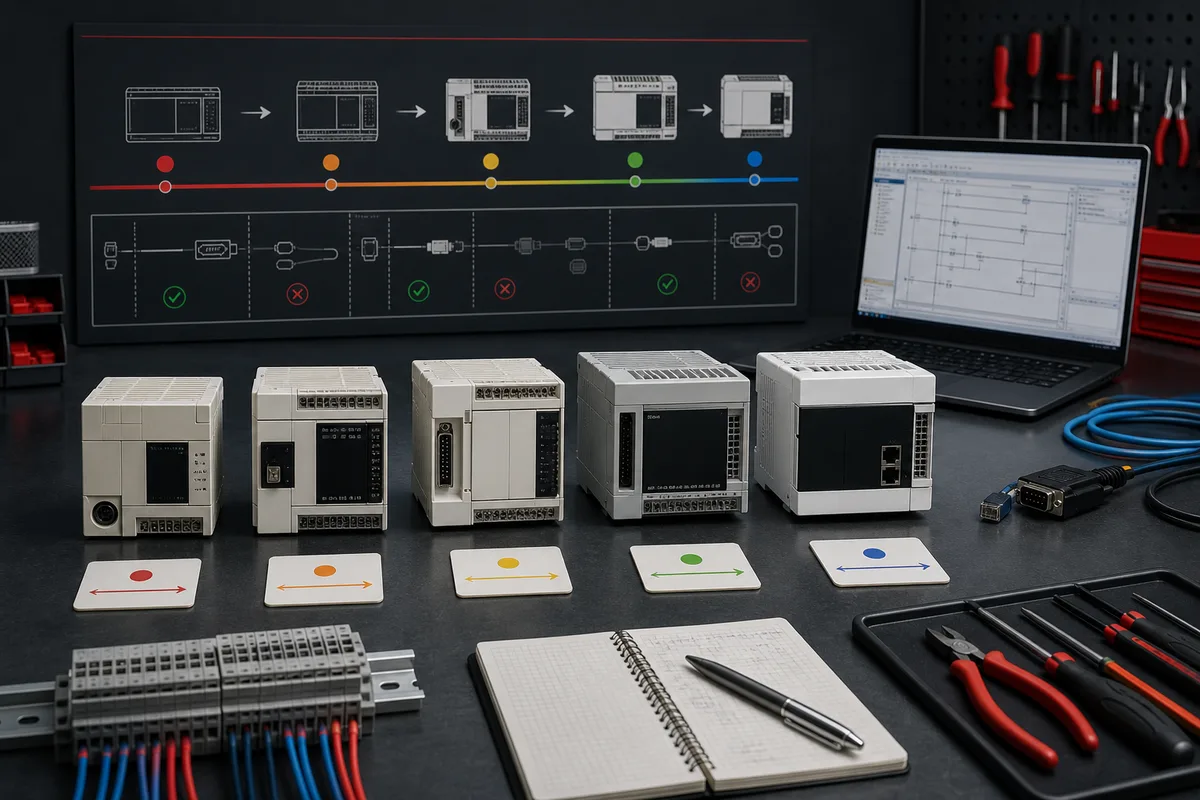
Select the FX5 high-speed path from the exact target
Built-in CPU functions and FX5-2HC/ES are different implementations
Current FX5U product records list built-in high-speed-counter capability, but the headline maximum is not an application guarantee. Exact usable channels and frequencies depend on CPU/model, input assignment, phase/mode, simultaneous use and waveform. Mitsubishi also provides dedicated iQ-F high-speed counter modules such as FX5-2HC/ES, with their own wiring, parameter, status, update and diagnostic interface.
Choose from the requirement outward:
- maximum and minimum pulse frequency, high/low width and acceleration;
- one-phase, direction, CW/CCW or quadrature A/B/Z method;
- voltage/interface and isolation;
- count range, preset, compare, latch and external control;
- needed timestamp, response or output action;
- CPU/module compatibility and system configuration;
- program data/status interface and update timing;
- diagnostics and required failure response; and
- commissioning equipment and representative encoder/load.
The current FX5-2HC/ES hardware manual points users to the module user manual for details. Treat that separation seriously: a small installation sheet is not the complete behavior contract. Resolve the current full manual, the exact GX Works3 module parameters and supported CPU/firmware before wiring or code.
Convert counts into engineering units safely
For a rotary encoder:
PositionUnits = (SignedCount - ZeroOffset) × UnitsPerRevolution / EffectiveCountsPerRevolution
“Effective” depends on whether the configured mode counts one, two or four edges per encoder cycle and on any mechanical gearing. Use signed/wrap-aware arithmetic appropriate to the hardware count range. A position jump near rollover can be a subtraction error rather than motion. Calculate the delta in the counter's modular number system or extend it under a proven update-rate condition.
For speed, compute count delta over a measured interval and carry timestamp quality. A fast task with only a few pulses produces quantization; a long interval reacts slowly. Compare expected minimum/maximum delta and reject stale or physically impossible values. Do not use an unvalidated speed estimate for a safety function.
Implement CTU, CTD and CTUD without mixed ownership
Use one named instance per requirement
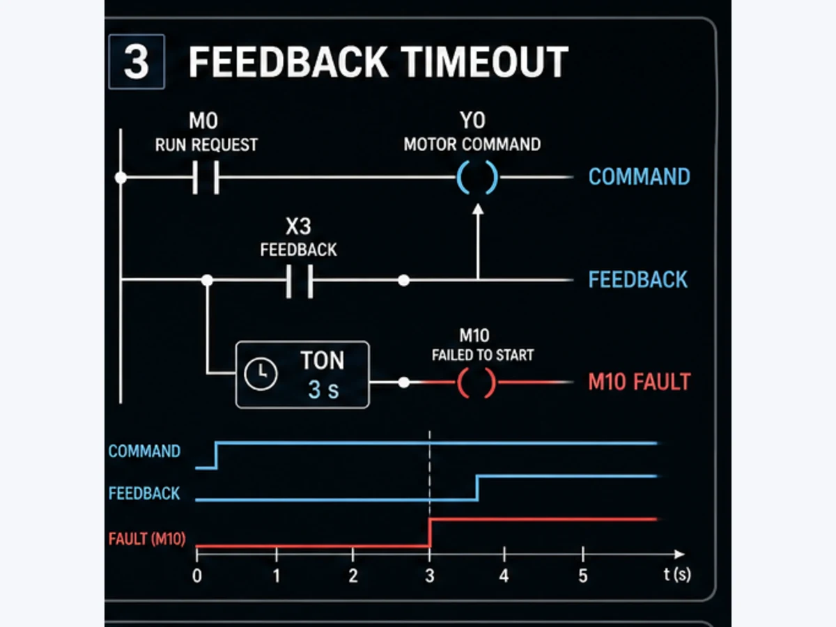
The current iQ-F instruction reference documents CTU, CTD and CTUD standard function blocks. Treat each instance as memory. CTU changes its current value on documented rising events at its count-up input and exposes completion/current value; CTD answers a down-count requirement; CTUD has separate up/down paths plus reset/load behavior. Verify exact types and priority in the current manual and GX project.
Vendor-neutral Structured Text intent might read:
CaseCount(
    CU := AcceptedCasePulse,
    R  := AcceptedBatchReset,
    PV := BatchTarget
);

BatchAtTarget := CaseCount.Q;
BatchCountValue := CaseCount.CV;
Do not paste this into a project without selecting the supported block/type and compiling. Do not call CaseCount in two programs. Do not also write its state from a C-device instruction. Validate startup edge memory: if CU is already true when execution begins, the first-count behavior must match the requirement.
Define simultaneous up/down and setting changes
For buffer occupancy, test entry and exit in the same scan. A net-zero requirement, defined priority or fault may be appropriate; never assume. Define underflow/overflow behavior, not merely a display clamp. If the recipe changes PV below the current value, decide whether completion changes immediately, the change is deferred to next batch, or the request is rejected.
Simulate logic, then validate the acquisition boundary
Use GX Works3 or GX Works2 for the exact project
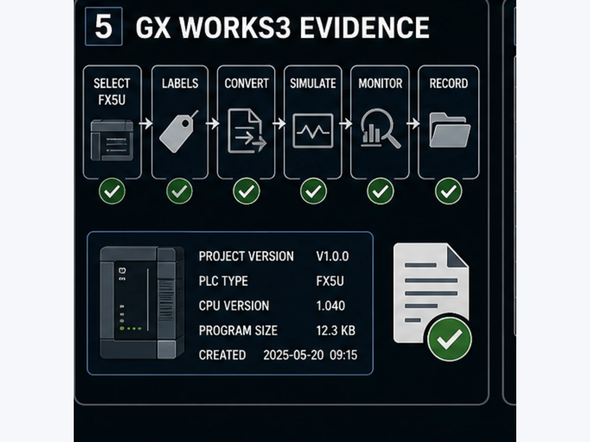
Open a controlled working copy in the compatible engineering environment. Confirm CPU, firmware, program/task, labels/devices, device/latch settings and module parameters. Convert/compile and inspect warnings. Use simulation only where Mitsubishi documents support for the selected target and feature.
An ordinary Boolean sequence can test qualification, count threshold, reset arbitration and state transition. Simulation cannot prove main-unit input response, electrical pulse shape, high-speed resource allocation, FX5-2HC/ES behavior, encoder phase, wiring, noise, mechanics or process response. Perform representative hardware tests under an approved plan.
Troubleshoot by the first failed count boundary
Preserve evidence before resetting
Record the physical event, input waveform/status, raw X or module channel, qualified event, C/FB current value, completion, sequence state, force/test state, diagnostic record and output/process result. Resetting first destroys the distinction between missed input, program gating and stale completion.
| Symptom | First failed-boundary test | Avoid |
|---|---|---|
| raw X never changes | terminal waveform versus exact input/common/filter | rewriting counter logic |
| raw X changes but C does not | driving condition, program route, task and reset | replacing sensor immediately |
| C changes but completion never does | setting source/type and threshold trace | forcing completion contact |
| completion true but sequence stays | state transition and one-writer ownership | editing the counter |
| high-speed value wrong direction | A/B phase or direction assignment | negating value without fixing configuration |
| high-speed value jumps | waveform/noise, scale and wrap arithmetic | arbitrary filter increase |
| count lost at restart | latch/device/instance configuration and startup code | assuming battery or retain defaults |
| HMI total differs | tag mapping, update, datatype and rollover | trusting the display over controller evidence |
Watch for online-change and force artifacts
After an online edit, do not assume a newly added stateful counter begins in the intended state. Establish and document its reset/initialization condition. Review forces and device tests before and after diagnosis. A forced qualified pulse, value or completion state can make downstream logic appear correct while the physical path remains untested.
Migrate an FX3 counter to FX5 by behavior
Do not translate C numbers one for one
Inventory every FX3 counter, associated special device, input allocation, setting source, cross-reference, latch behavior and restart result. For a high-speed counter, include terminal/mode, allowed frequency, phase/direction, reset/start, compare and application scale. Then choose the FX5 mechanism that satisfies that requirement—device path, standard FB, built-in HSC or module—not the one with the most familiar symbol.
| FX3 evidence | FX5 decision | Required regression |
|---|---|---|
ordinary OUT C batch count |
device instruction or named CTU |
edge, target, reset, startup and threshold |
| latched partial batch | explicit device/instance retention and reconciliation | stop/run, power loss and cold/warm restart |
| C235–C255 high-speed mode | exact FX5 built-in/module channel configuration | terminals, mode, rated extremes, direction and errors |
| special M device direction/control | named state and supported parameter/control interface | both directions and simultaneous boundaries |
| HMI reads C device directly | stable published tag/label interface | value, quality, datatype, reset and rollover |
| compare drives output | state-machine request with one output owner | normal, limit, fault, restart and rollback |
Keep the old system reproducible until the representative test matrix passes. A converted program that compiles proves syntax only. It does not prove pulse acquisition, scan behavior, I/O, motion, process or safe response.
Acceptance tests before release
Download the Mitsubishi counter acceptance matrix. At minimum run these cases with actual and expected evidence:
- reset establishes the documented initial value/status;
- first valid false-to-true event changes the count once;
- held true input does not create repeated ordinary counts;
- just-shorter-than-valid noise is rejected under the designed filter;
- minimum valid pulse is captured with margin;
- maximum credible rate does not lose or add events;
- event at threshold changes completion and sequence exactly once;
- count and reset in the same cycle follow the documented priority;
- setting changes below/equal/above current value follow policy;
- up/down or A/B direction works at slow and representative speed;
- underflow, overflow and rollover behavior is observed and handled;
- stop/run, warm/cold restart and power interruption follow retention policy;
- input loss/noise/implausible rate produces the designed diagnostic response;
- force/test/temporary logic is cleared and independently reviewed;
- online/offline project, parameters and target identity compare cleanly; and
- rollback restores the verified prior behavior.
Simulation is useful for ordinary event and state logic. It cannot close the electrical, high-speed, machine, process or safety gates.
Mitsubishi counter answer map
| Question | Concise answer | Boundary |
|---|---|---|
| How does a Mitsubishi PLC counter work? | a documented event changes device or FB state until reset/load/limit behavior applies | exact family/instruction controls semantics |
| Does a held input count every scan? | an edge counter should change once for one accepted false-to-true event | trace actual instruction behavior |
| What is an FX3U high-speed counter? | a configured C235–C255 resource tied to defined inputs/modes | select from exact allocation/performance tables |
| Does FX5 use CTU? | current iQ-F references document CTU/CTD/CTUD standard FBs | verify project/library/type and instance |
| Why are products double counted? | repeated physical/raw edges, duplicate execution or overlapping owners | correlate waveform, X input and program trace |
| Why are fast pulses missed? | filter/update/scan cannot observe them or HSC is misconfigured | measure minimum width and complete path |
| How do I reset a counter? | use one authorized reset owner under a defined machine state | prove same-cycle count/reset priority |
| Is a counter retentive? | only if exact device/instance/latch and restart evidence says so | test stop/run and power loss |
| Can FX3 counters copy to FX5? | migrate behavior and resources, not C numbers | regression-test every boundary |
| Can a browser simulator emulate Mitsubishi HSC? | no; it can practise edge/state reasoning only | repeat in GX target and hardware |
Frequently asked questions
What is a Mitsubishi PLC counter?
It is a stateful device instruction, function-block instance or hardware counting resource whose current value/status changes on defined events. Identify the exact FX CPU, project model, instruction or module before interpreting a C number or mnemonic.
How do I program a Mitsubishi PLC counter for ten products?
Create one qualified false-to-true product event, execute one counter owner with a setting of ten in the documented form, use its completion status to request the next sequence state and reset only through an accepted new-batch condition. Test held, bouncing, fast and simultaneous reset events.
Does OUT C0 K10 count levels or edges?
In the documented FX device-counter pattern, the counter advances on an off-to-on transition of its driving instruction condition, not every scan that it remains true. Verify the exact CPU/instruction reference and trace the current value because other counter models are not automatically identical.
Why does a Mitsubishi counter count twice?
The sensor or raw input may produce two edges, the qualification may chatter, the same C device or FB instance may execute in more than one path, or another writer may alter its state. Align physical waveform, raw X, accepted event and counter trace to find the first duplication.
Why does my Mitsubishi counter miss pulses?
The pulse may be shorter than the input filter/update/scan path, the program may not execute, gating or reset may overlap, or the selected high-speed channel/mode may be wrong. Measure the waveform and compare it with the exact acquisition configuration before rewriting logic.
Which FX3U high-speed counter should I use?
Select from the FX3U manual's C235–C255 allocation table using the required one-/two-phase method, count/direction/start/reset terminals, active resource conflicts and permitted frequency. Do not choose from an isolated example.
Does FX5U support CTU, CTD and CTUD?
The current MELSEC iQ-F instruction reference documents those standard counter function blocks. Confirm that the exact project, CPU, firmware, library/type and instance call support the intended behavior; a named FB is not the same state as a legacy C device.
How do I reset a Mitsubishi counter safely?
Give reset one owner, accept a momentary request only in a documented stopped or batch-transition state, preserve required results/first-out evidence and test reset together with a count event. Do not scatter unconditional reset instructions across programs.
Are Mitsubishi counters retained after power loss?
Retention depends on the exact device/latch allocation or FB-instance storage, CPU configuration, battery/storage condition and restart code. Prove stop/run, warm/cold restart and power-interruption behavior on the controlled target.
What is the difference between an ordinary and high-speed counter?
An ordinary counter evaluates a program-visible condition through the cyclic path. A high-speed counter captures configured terminal pulses outside that ordinary path. High-speed acquisition still needs correct wiring, filter, phase/mode, scaling, diagnostics and application tests.
Can GX Works simulation validate a high-speed counter?
It can validate supported program logic and state handling in its declared target context. It cannot prove electrical pulse levels, input response, module behavior, encoder phase, wiring, noise, mechanical ratio or representative machine speed.
Can a browser counter simulator replace GX Works3?
No. The same-owner browser lab is vendor-neutral and useful for edge, reset, threshold and fault reasoning. It does not emulate Mitsubishi instructions, device/latch allocation, CPU/task, built-in HSC, FX5-2HC/ES, I/O or process behavior.
Primary sources and review trail
- Mitsubishi Electric, FX3S/FX3G/FX3GC/FX3U/FX3UC Programming Manual — Basic & Applied Instructions. Ordinary and high-speed C-device behavior, resource assignments and examples.
- Mitsubishi Electric, FX3U Hardware Manual. C235–C255 hardware-counter inputs, filters, response and overlap cautions.
- Mitsubishi Electric, MELSEC iQ-F FX5 Programming Manual — Instructions, Standard Functions/FBs. Current counter device/instruction and CTU/CTD/CTUD/COUNTER_FB_M reference.
- Mitsubishi Electric, MELSEC iQ-F FX5 Programming Manual — Program Design. Program, task, device/label and execution design context.
- Mitsubishi Electric, MELSEC iQ-F FX5U/FX5UC User's Manual — Hardware. Current CPU hardware, I/O and high-speed function boundaries.
- Mitsubishi Electric, FX5-2HC/ES Hardware Manual. Dedicated module installation/wiring boundary and associated-manual route.
- Mitsubishi Electric, MELSEC iQ-F manual download index. Resolve current CPU, high-speed counter module and firmware-specific manuals.
- Mitsubishi Electric, current MELSEC iQ-F CPU lineup. Current FX5 family and built-in-function positioning.
- Mitsubishi Electric, current iQ-F specification search. Orderable model and catalog-specific specification evidence.
- Mitsubishi Electric, GX Works3 operating manual. Current project, conversion, monitor, compare and simulator workflow.
- Mitsubishi Electric, GX Works3 manual index. Resolve the current engineering-software documentation.
- Mitsubishi Electric, FX5 simulation support FAQ. Target-specific simulator support boundary.
- Mitsubishi Electric, MELSEC-F FX3 product/manual area. Installed-base family context and manual routing.
- IEC, IEC 61131-3:2025 publication record. Current PLC language/standard-function context; vendor implementation still controls.
- NIST, SP 800-82 Rev. 3. OT engineering access, change, backup and recovery context.
- OSHA, Control of hazardous energy. US servicing energy-control boundary where applicable.
- PLC Programming IO, Mitsubishi PLC programming tutorial. Local broader GX project owner with its own primary-source trail.
- PLC Programming IO, PLC edge/debounce guide. Local cross-vendor signal-qualification specialist.
Mitsubishi manuals and the approved project, drawings, machine risk assessment, electrical design and site procedures take precedence. Product names and marks belong to their owners. Review official manuals again for the exact target and revision before implementation.
Handoff checklist
- Exact CPU, firmware, GX release and controlled project are recorded.
- Counter device/instruction/FB/module and every writer/caller are identified.
- Physical event, electrical input, filter and acquisition path are measured.
- Setting, type, current value, completion, reset and retention are explicit.
- Ordinary scan margin or high-speed channel allocation is proven.
- Bounce, minimum pulse, maximum rate and missed/extra edge cases pass.
- Reset/count simultaneity, restart, rollover and setting changes pass.
- Downstream sequence, output, feedback and process response pass separately.
- Simulation limitations and remaining hardware tests are recorded.
- Forces/test devices are cleared; project/parameters compare cleanly.
- Backup and rollback are verified before release.
The useful result is not a counter that happens to display ten. It is a traceable chain from one physical event to one accepted edge, one state owner, one threshold decision and one independently verified machine response.
Now run it · free to start
Practise Mitsubishi-style PLC logic in your browser
Work X/Y/M/D devices, latches, timers and counters without GX Works. An independent learning tool — free to start.
Ownership disclosure: PLC Programming IO and PLC Simulation Software are operated by the same publisher.
PLC Programming IO Editorial Team
Industrial automation education, references, and software testing
The PLC Programming IO Editorial Team publishes sourced industrial-automation education and documents how material is reviewed, tested, and corrected. A team byline means the publisher is responsible for the page; it does not represent a fictional person or imply an engineering licence.
Coverage:
- • PLC programming concepts and examples
- • Vendor software tutorials and comparisons
- • SCADA, HMI, protocols, and instrumentation
- • Training, careers, and reference material
Review standard:
- • Prefer primary and official sources
- • Record software versions when material
- • Separate tested facts from estimates
- • Publish material corrections
Important scope note
This site provides education, not project-specific engineering approval. Safety, code, and compliance decisions require a qualified person with access to the actual machine and jurisdiction.