Ladder Logic Contacts, Coils and Power Flow
Read direct and negated contacts as Boolean tests, combine series and parallel paths, understand coil writes, and troubleshoot ladder logic by scan order.
Review status: Editorially reviewed against cited IEC 61131-3:2025, Rockwell Automation, Schneider Electric, CODESYS and Siemens documentation; exact vendor instruction, controller scan, initialization, retention, I/O mapping, safety design and site procedures require verification
Direct answer
In ladder logic, a contact reads or tests a Boolean value and a coil writes a Boolean value. A direct contact (--| |--) passes the incoming rung condition when its assigned bit is 1/TRUE. A negated contact (--|/|--) passes it when the assigned bit is 0/FALSE. Contacts in series implement an AND relationship; parallel branches implement an OR relationship. The resulting rung condition reaches a coil or another output instruction on the right.
An ordinary coil normally writes both states: true rung condition writes 1, and false rung condition writes 0. A set/latch coil writes 1 only when enabled; its false rung does not undo the prior set. A reset/unlatch coil writes 0 only when enabled. Exact prescan, postscan, retention and restart behavior is controller-specific.
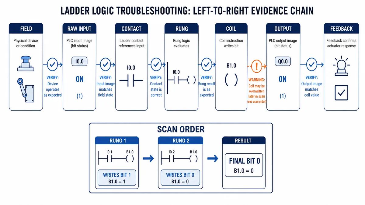
The contact symbol is a software test, not a physical contact specification. A negated ladder contact does not prove that the field device is physically normally closed, de-energize-to-trip, fail-safe or part of a safety function. Trace the full chain: physical state → electrical input → raw PLC bit → mapped/application bit → contact truth → rung result → coil writer → output mapping → physical feedback.
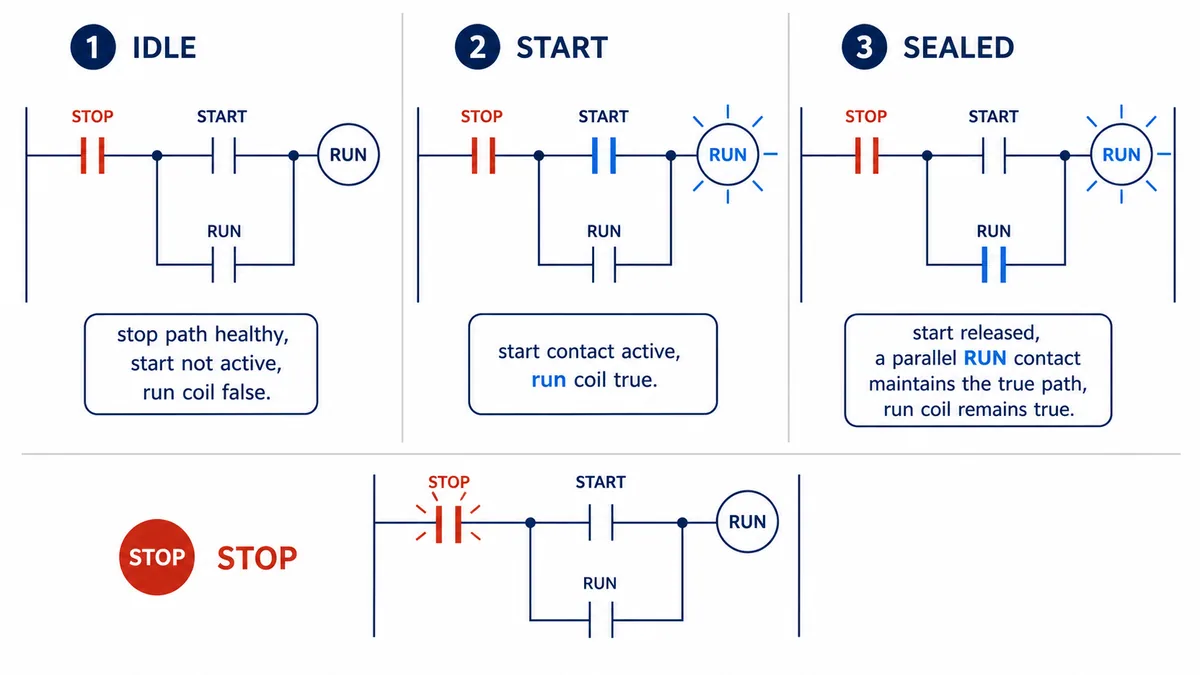
A ladder logic latch or seal-in circuit is not one interchangeable instruction. A seal-in uses an ordinary coil and its own contact in a parallel holding path, so a false stop/permit path makes the ordinary coil write false. A latch/set instruction makes a one-sided true write and needs a separately owned reset/unlatch. Both can remember an operator request, but their skipped-routine, duplicate-writer, restart and migration behavior differs. The seal-in sequence and test matrix below own that combined query; use the Set/Reset PLC ladder guide for deeper reset/set priority, vendor instruction and retention analysis.
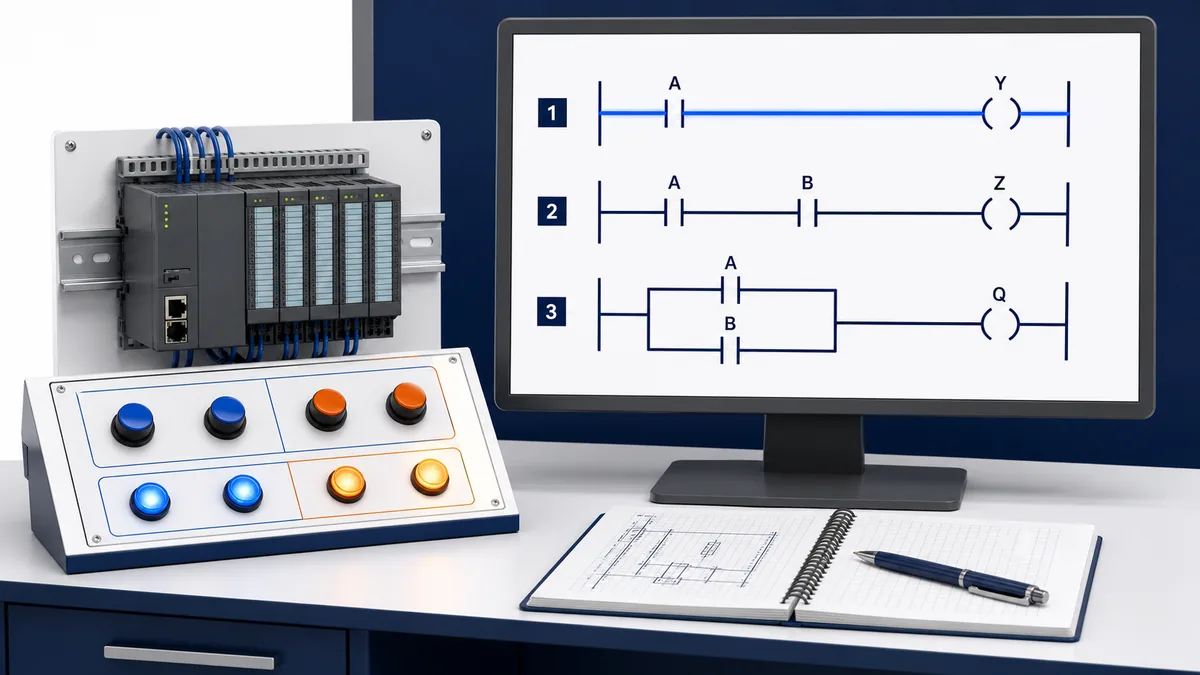
Read ladder power flow as Boolean evaluation
Power flow is a model, not electrical current
Ladder Diagram (LD) inherited the visual grammar of relay schematics: vertical rails, horizontal rungs, contact-like conditions and coil-like results. IEC 61131-3 defines Ladder Diagram as a graphical programmable-controller language. The left rail supplies a conceptual TRUE condition into a network; the software evaluates elements and connections toward the right.
No electrical current flows through a drawn software contact. Online editors often color a path green or blue to show a true rung condition, but that highlight only reports evaluated program state. It cannot prove input voltage, output current, actuator motion, network health, execution frequency or the absence of another later writer.
| Ladder surface | Software meaning | What it does not prove |
|---|---|---|
| left rail | starting TRUE condition for evaluating a network/rung | energized control voltage exists in a cabinet |
| direct contact | assigned Boolean is TRUE and incoming path is true | physical contact is normally open or field signal is healthy |
| negated contact | assigned Boolean is FALSE and incoming path is true | physical device uses a normally closed contact |
| blue/green highlight | editor reports true/evaluated path at that observation | continuous truth between screen refreshes or physical output state |
| coil | writes a Boolean according to its instruction semantics | a physical relay coil is energized |
| branch | alternate Boolean path combines with neighboring paths | parallel field wiring exists |
Separate bit state, contact truth and rung truth
Three values can be confused:
- Bit state is the assigned variable's current
0or1. - Contact truth is the direct or negated test result for that bit.
- Rung-condition-out is contact truth combined with the incoming path and every series/parallel element before it.
A direct contact assigned to a 1 bit can still sit on a false branch if an earlier series condition is false. A negated contact assigned to 0 is true, yet the final rung may remain false because another required path is missing.
Apply the contact truth table
Direct contact tests for one
A direct contact is true when its assigned Boolean is true. Rockwell calls this XIC, Examine If Closed; other systems may call it normally open, direct contact, examine-on or simply contact. The most portable mental model is “test whether the assigned Boolean equals TRUE.”
Negated contact tests for zero
A negated contact is true when its assigned Boolean is false. Rockwell calls it XIO, Examine If Open; other systems use normally closed, inverted or negated contact. Read it as “test whether this Boolean equals FALSE,” not as a claim about field hardware.
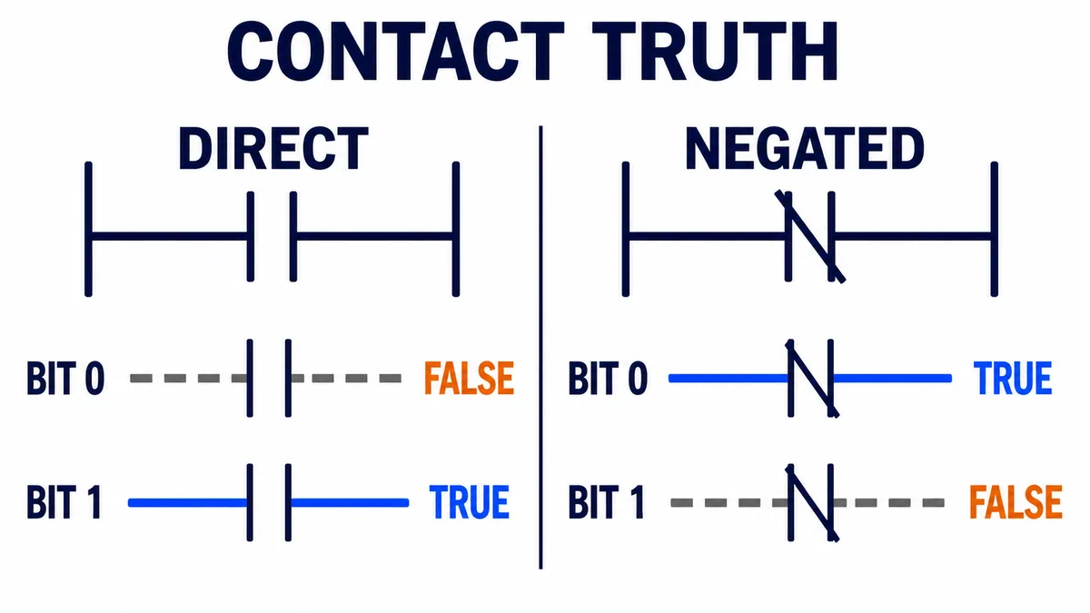
| Assigned bit | Direct contact | Negated contact |
|---|---|---|
0 / FALSE |
false/open logical path | true/closed logical path |
1 / TRUE |
true/closed logical path | false/open logical path |
Translate physical devices in two steps
Suppose a pushbutton has a physical normally closed contact and the PLC input bit is 1 while the circuit is healthy. A direct ladder contact on that input is true in the healthy state. If the wire opens or the button is pressed, the input falls to 0 and the direct ladder contact becomes false. The physical NC contact led to a direct software test—not a negated one.
Conversely, a physical normally open sensor can produce a bit that is 0 until actuated. A negated contact on that bit would be true while the sensor is inactive. Physical contact form and ladder symbol are two different layers.
| Layer | Question | Evidence source |
|---|---|---|
| process | what real condition exists? | observed state and approved process instrumentation |
| device | what output behavior does the sensor/switch provide? | exact device datasheet and wiring drawing |
| electrical input | what voltage/current reaches the PLC point? | approved qualified-person test and module documentation |
| raw bit | what Boolean/status does the input module publish? | online raw I/O data plus connection quality |
| application mapping | is raw data inverted, buffered, filtered or quality-gated? | mapping routine, alias and cross-reference |
| ladder contact | does this instruction test TRUE or FALSE? | exact vendor instruction semantics |
Combine contacts with series and parallel paths
Series contacts implement AND
Two direct contacts A and B in series allow a true path only when A = TRUE and B = TRUE. Adding a negated contact changes only its operand test. For example, direct A in series with negated B means A AND NOT B.
Parallel branches implement OR
Two contacts A and B on parallel branches produce a true combined path when either branch is true. The logic is A OR B. If each branch contains series elements, solve each branch first and then OR the branch results.
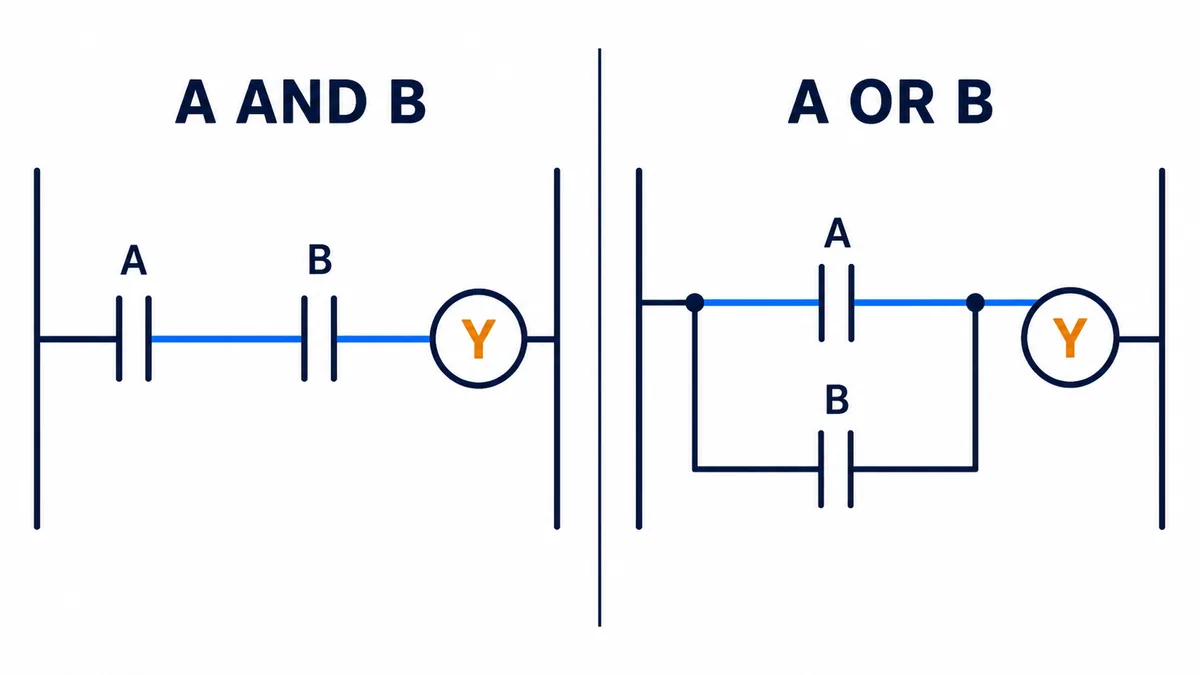
| Ladder arrangement | Boolean expression | True cases |
|---|---|---|
| A then B in series | A AND B |
only A=1, B=1 |
| direct A then negated B | A AND NOT B |
only A=1, B=0 |
| A parallel B | A OR B |
A=1 or B=1 or both |
| two branches: A-B and C-D | (A AND B) OR (C AND D) |
either complete branch true |
| A then branch B/C | A AND (B OR C) |
A true plus either B or C |
Do not simplify a network by visual impression. Write the Boolean expression or enumerate a truth table. Pay particular attention to branches that join after an interlock: a misplaced branch can bypass a condition that was intended to constrain every path.
Live mini-lab
Try it: press START, then STOP
A stop-dominant seal-in rung: START latches the motor output through its own contact, and STOP breaks the circuit.
Watch the output lamp: it stays on after START until you press STOP.
Free to start · runs in your browserOpens plcsimulationsoftware.com — same team
Understand ordinary, set and reset coils
Ordinary coil writes both true and false
An ordinary IEC coil stores the incoming Boolean result. Rockwell OTE sets or clears its target according to the rung condition. Schneider and CODESYS describe the ordinary coil similarly. Therefore the false state of the rung is an active write of false, not “nothing happens.”
This matters when two ordinary coils target the same bit: the later executed writer can overwrite the earlier result. It also matters when a routine stops executing; a bit may no longer be written in the same way, and platform-specific prescan/postscan or task behavior becomes relevant.
Set and reset coils write one state selectively
A set/latch coil writes TRUE when its rung is true and normally performs no opposite write while its rung is false. A reset/unlatch coil writes FALSE when its rung is true and normally performs no opposite write while its rung is false. They form explicit state memory only when ownership, initialization and reset paths are designed.
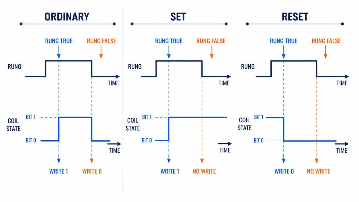
| Coil family | True rung action | False rung action | Main design obligation |
|---|---|---|---|
| ordinary / direct / OTE | write bit TRUE | write bit FALSE | exactly one final owner and known execution |
| negated coil | write inverse of rung result | also writes inverse | make inversion visible and justified |
| set / latch / OTL | write TRUE | no corresponding FALSE write at this instruction | every reset/initialization/recovery path defined |
| reset / unlatch / OTU | write FALSE | no corresponding TRUE write at this instruction | pair with intended set owner and priority rules |
| edge/pulse coil | vendor-specific one-cycle/edge behavior | vendor-specific state/storage | exact execution interval and edge memory proven |
“Retentive” in an instruction description does not automatically guarantee power-loss persistence, download behavior or nonvolatile storage. Those are controller, memory, project and configuration properties. Test transitions through program/run mode, power cycle, download, first scan and fault recovery where relevant.
Build and critique a seal-in rung
See how the holding contact works
A conventional start/stop seal-in pattern has a momentary start request in parallel with a contact that reflects the run memory, while a stop/permit condition constrains both paths. On start, the coil becomes true. On the next evaluation, the run contact becomes true and maintains the path after the start request is released. Removing the stop/permit path makes the ordinary coil false, which opens the run contact.
Test the cases the textbook diagram omits
| Case | Question the design must answer |
|---|---|
| PLC starts with run bit false | does the equipment remain stopped until a new permitted request? |
| PLC starts with run bit true | can stored/mapped state cause an unintended restart? |
| start remains stuck true | does a stop release remain effective, and what happens when stop clears? |
| stop/permit chatters | is the command stable, diagnosed and safe for the process? |
| output feedback fails | does command time out and identify the missing response? |
| auto mode also requests run | which mode owns the command, and can manual/auto overlap? |
| communication is lost | do stale HMI requests persist, expire or become invalid? |
| task/routine is skipped | does command state freeze, clear or get written elsewhere? |
A seal-in rung is ordinary command memory, not a safety function. Emergency stop, guard monitoring and other required risk-reduction functions need the validated safety system, appropriate devices, diagnostics, architecture and lifecycle.
Treat scan order and multiple writers as first-class behavior
Later writes can win within one execution
Many PLC programs execute ordered rungs/routines. If rung 1 writes a bit true and a later rung 2 writes the same bit false, later logic can determine the value observed after those executions. Siemens explicitly warns that when the same coil address appears in multiple program locations, the last calculation can determine the physical output update. Rockwell warns about operands being overwritten.
The exact scheduler can be more complex than a single top-to-bottom scan: tasks can preempt, routines can be conditional, I/O can update asynchronously and external systems can write tags. “Last rung wins” is therefore a useful local warning, not a universal concurrency model.
Find every direct and indirect writer
Use cross-reference and instruction usage tools, then include indirect writers:
| Writer surface | Why a simple coil search can miss it |
|---|---|
| ordinary/set/reset coil | same bit may appear under aliases or multiple routines |
| move/copy/fill | a word, array or structure write can overwrite a member bit |
| structured text | assignment sits outside ladder routine searches |
| HMI/SCADA/external client | network write does not look like a coil |
| message or produced/consumed data | ownership and update timing differ from local logic |
| force | displayed/physical behavior can be overridden outside normal rung result |
| module/technology object | controller or module updates a structure member |
One final command owner is easier to test: other routines produce requests, permissives and interlocks; one arbitration routine writes the final application command; one mapping layer writes the physical output.
Use edge contacts and one-shots deliberately
An edge is an event relative to stored history
A rising-edge instruction is true for one execution when a condition changes from false to true according to its stored prior state. A falling-edge instruction responds to true-to-false. Rockwell provides ONS/OSR/OSF variants; IEC systems provide rising/falling transition contacts or function blocks according to implementation.
“One scan” means one execution of that instruction in its task/routine context. If the routine is called conditionally or the task runs at a different interval, the observed pulse and history behavior can differ from a naive continuous-scan assumption.
| Edge risk | Failure mode | Better evidence |
|---|---|---|
| reused storage | two events interfere through one memory bit | unique documented edge instance/storage |
| conditional routine call | history is not updated while routine is skipped | test entry/exit and first re-execution |
| input pulse shorter than task interval | event never sampled | device/module capture, faster task or engineered event mechanism |
| HMI bit held true | edge occurs once, then no repeats | command handshake and timeout/reset contract |
| power/mode transition | first execution creates or suppresses an edge | exact controller prescan/initialization tests |
| event triggers non-idempotent action | duplicate/missed event corrupts count/sequence | transaction/sequence ownership and diagnostics |
Troubleshoot from field condition to feedback
Follow the evidence chain left to right
| Symptom | First discriminating evidence | Likely boundary | Avoid |
|---|---|---|---|
| field device active, raw input false | module/channel status, connection, electrical signal and exact mapping | field wiring, supply, module or wrong point | inverting ladder contact first |
| raw input true, direct contact false | exact tag/alias, online project match and data type/member | wrong operand or stale/mismatched project | assuming editor highlight is live truth |
| contacts true, rung false | upstream series element, branch joins and instruction errors | misunderstood Boolean path | forcing rung result |
| rung true, ordinary coil false | instruction execution, duplicate/indirect writer and task order | later writer or routine not executing as assumed | adding another coil to “reinforce” it |
| coil bit true, output tag false | arbitration/mapping, force, mode, interlock and output owner | application-to-I/O mapping | rewiring before checking mapping |
| output tag true, field output off | module status, output supply/load, protection and feedback | I/O/electrical/load boundary | treating coil highlight as voltage proof |
| set bit will not reset | reset rung truth, task/routine call, tag identity and other set writers | missing/unexecuted reset or priority conflict | power cycling as logic repair |
| bit flickers | trends with task timestamps, all writers and input quality | bounce, race, asynchronous or duplicate ownership | adding arbitrary debounce everywhere |
Capture a reproducible ladder incident
Record controller/project identity, mode, task/routine execution, timestamp, raw input and quality, mapped tags, rung conditions, coil target, every writer, forces, output module state and physical feedback. A screenshot without project revision, time and tag values is weak evidence. A trend can reveal changes between screen refreshes.
Use the PLC input and output troubleshooting guide for the physical-to-tag path and the intermittent PLC fault guide for time-correlated evidence.
Review ladder rungs for maintainability
Apply a rung-quality checklist
| Review gate | Pass question |
|---|---|
| intent | does the comment explain behavior and consequence, not restate symbols? |
| naming | do tags describe process meaning, state and ownership? |
| polarity | is the healthy/active/fault meaning explicit across physical and software layers? |
| ownership | is there one final writer, or is arbitration fully documented? |
| execution | is task/program/routine scheduling and conditional calling understood? |
| state | are set/reset, initialization, restart and recovery cases tested? |
| timing | are one-shots, pulses, timers and feedback windows proven against task timing? |
| diagnostics | can a maintainer see which permit/interlock blocks the command? |
| safety | are required safety functions outside ordinary control logic and validated? |
| tests | do normal, boundary, fault, restart and restoration cases trace to requirements? |
Long rungs are not automatically bad, but invisible ownership is. Break reusable calculations or equipment behavior into clear units without hiding the decisive final command path. Expose reason bits for permissives and interlocks so operators see why a rung is false.
Diagnostic answer map for search and AI-assisted troubleshooting
| User or AI query | Concise answer | Required qualification |
|---|---|---|
| What does a ladder contact do? | It tests a Boolean and passes the incoming rung condition when that test is true. | Direct tests 1; negated tests 0. |
| Is a normally closed PLC contact a physical NC switch? | No. The drawn negated contact tests a false bit. | Trace device, wiring, raw bit and mapping separately. |
| What does a ladder coil do? | It writes a Boolean based on the instruction and incoming rung condition. | Ordinary, set, reset and edge coils differ. |
| What is ladder power flow? | A left-to-right graphical representation of Boolean truth through a network. | It is not electrical current or proof of field output. |
| Are series contacts AND logic? | Yes, every series condition in that path must be true. | Negated contacts contribute NOT of their assigned bit. |
| Are parallel contacts OR logic? | Yes, any complete true branch can pass the rung condition. | Check where branches begin and rejoin. |
| Why is a green rung output off? | Another writer, mapping, force, module fault or electrical/load issue may exist. | Follow coil bit through final output and feedback. |
| What is the difference between OTE and OTL? | OTE writes true and false with the rung; OTL writes true when enabled and otherwise does not clear it. | OTU/reset and restart behavior must be designed. |
| What does last rung wins mean? | A later executed write to the same bit can overwrite an earlier write. | Tasks, external writes and asynchronous data make global order more complex. |
| Is a seal-in rung a safety circuit? | No, it is ordinary software command memory. | Required safety functions need validated safety architecture. |
Frequently asked questions
What is the difference between a contact and a coil in ladder logic?
A contact reads/tests a Boolean condition and contributes to rung truth. A coil writes a Boolean according to the final incoming rung condition and its coil type. Contacts do not write their assigned bit; coils do.
When is a normally open ladder contact true?
A direct or normally open ladder contact is true when its assigned Boolean is 1/TRUE and the incoming rung path is true. The symbol does not tell you the physical device's contact arrangement.
When is a normally closed ladder contact true?
A negated or normally closed ladder contact is true when its assigned Boolean is 0/FALSE and the incoming path is true. Many vendors use different names, so verify the instruction semantics.
Why use a normally closed physical stop but a direct PLC contact?
If the healthy physical NC loop energizes the PLC input, its input bit is 1 while healthy. A direct ladder contact then tests that healthy 1. Opening the circuit makes the bit and direct contact false. The exact circuit and safety role still require engineered documentation.
Do two contacts in series always mean AND?
They AND their individual Boolean test results along that path. A negated contact contributes the inverse of its assigned bit, so direct A in series with negated B represents A AND NOT B.
Can I use the same output coil more than once?
Many platforms allow it, but later or higher-priority writers can overwrite earlier results and make troubleshooting dependent on execution order. Prefer a single documented final owner and explicit request/arbitration logic.
What is the difference between a seal-in coil and a latch coil?
A seal-in pattern uses an ordinary coil plus its own contact in a parallel holding path; when the constraining path becomes false, the coil writes false. A latch/set instruction makes a one-sided true write and needs a separate reset/unlatch action.
Does a latched PLC bit survive power loss?
Not necessarily. Latch semantics describe what the instruction does when executed or not enabled. Power-loss persistence, downloads, controller mode transitions and nonvolatile behavior depend on the exact controller, memory and configuration.
What does one scan mean for a one-shot?
It means one execution interval of that instruction in its task/routine context. A conditionally called routine or different task period changes the real time and history behavior, so test the exact scheduler.
Why is the output coil true but the machine does not move?
The coil may be an internal command rather than the physical output, a later writer may change it, output mapping/interlocks may block it, or the module/load/process may be faulty. Verify every boundary through physical feedback.
Sources, review scope, and limitations
This guide was reviewed on August 28, 2026 against current public sources. Ladder syntax and execution differ across vendors, controller families, firmware, task schedulers, editors and language profiles. Verify the exact platform and tested project.
- IEC 61131-3:2025 programmable-controller programming languages — IEC
- Studio 5000 Logix Designer v38 bit instructions — Rockwell Automation
- Output Energize (OTE) execution — Rockwell Automation
- Output Unlatch (OTU) execution — Rockwell Automation
- Logix 5000 Controllers Ladder Diagram, 1756-PM008 — Rockwell Automation
- Logix 5000 Controllers IEC 61131-3 Compliance, 1756-PM018 — Rockwell Automation
- Logix 5000 Controllers General Instructions, 1756-RM003 — Rockwell Automation
- Contact and coil behavior — Schneider Electric
- Set and reset coil behavior — Schneider Electric
- IEC ladder programming language elements — Schneider Electric
- CODESYS ladder coil, negated coil and set/reset behavior — CODESYS
- S7-1200 Easy Book ladder contact, coil and duplicate-address explanation — Siemens
- 29 CFR 1910.147, control of hazardous energy — OSHA
- 29 CFR 1910.333, electrical work practices — OSHA
The figures are conceptual editorial teaching diagrams, not vendor screenshots, compilable project code, electrical schematics, safety logic or field procedures. Symbols and labels illustrate Boolean relationships only. This page does not authorize online edits, downloads, forces, bypasses, output commands, rewiring, energized measurement or machine testing. Only qualified, authorized personnel following the site risk assessment, change control, hazardous-energy and electrical safe-work procedures, validated safety lifecycle, engineered drawings, exact manufacturer documentation and approved test plan should modify or test an installed control system.
Now run it · free to start
Learn a repeatable way to find the fault
Split a stopped machine into input, logic, output and physical response, and take the measurement that proves each stage. Practised on simulated machines. Free to start.
Ownership disclosure: PLC Programming IO and PLC Simulation Software are operated by the same publisher.
PLC Programming IO Editorial Team
Industrial automation education, references, and software testing
The PLC Programming IO Editorial Team publishes sourced industrial-automation education and documents how material is reviewed, tested, and corrected. A team byline means the publisher is responsible for the page; it does not represent a fictional person or imply an engineering licence.
Coverage:
- • PLC programming concepts and examples
- • Vendor software tutorials and comparisons
- • SCADA, HMI, protocols, and instrumentation
- • Training, careers, and reference material
Review standard:
- • Prefer primary and official sources
- • Record software versions when material
- • Separate tested facts from estimates
- • Publish material corrections
Important scope note
This site provides education, not project-specific engineering approval. Safety, code, and compliance decisions require a qualified person with access to the actual machine and jurisdiction.