Set/Reset PLC Ladder Logic: Scan Order, Priority and Testing
Build PLC Set/Reset ladder logic without hidden state: define the truth table, one writer, scan-by-scan behavior, restart policy, vendor dialect and acceptance evidence.
Review status: Editorially reviewed against current IEC 61131-3:2025 scope, Rockwell Studio 5000 Logix Designer v38 OTL/OTU help, Mitsubishi MELSEC iQ-F FX5 instruction manual JY997D55801AB, current CODESYS Ladder and Schneider Machine Expert help, Siemens S7-1200 guidance and OSHA hazardous-energy requirements; the equations, conveyor example, figures and downloads are original teaching artifacts, while exact instruction availability, precedence, storage, restart, download, scheduler, I/O and safety behavior require verification on the selected controller, firmware, engineering software and validated machine
Direct answer
Set/Reset PLC ladder logic stores a Boolean state instead of recalculating it from one rung on every scan. A true Set request writes the state to 1; a true Reset request writes it to 0; when neither request is true, the previous state is held. Rockwell commonly names the pair OTL/OTU, Mitsubishi uses SET/RST, and IEC-style editors commonly show Set/Reset coils or SR/RS blocks. Those names are conceptual equivalents, not proof of identical priority, retention or restart behavior.
Before drawing the rungs, choose what happens when Set and Reset are true together. A clear reset-dominant definition is:
NextState = (PreviousState OR SetRequest) AND NOT ResetRequest
That produces this contract:
| Set request | Reset request | Next state | Meaning |
|---|---|---|---|
| 0 | 0 | previous state | hold |
| 1 | 0 | 1 | set |
| 0 | 1 | 0 | reset |
| 1 | 1 | 0 | reset wins |
Put all request arbitration in one routine or block and give exactly one owner permission to write the state. Keep the physical output downstream: RunMemory can store an accepted ordinary-control request, while RunCmd still depends on mode, process permits, ordinary faults and the project’s output mapping. A Set/Reset bit is not an emergency-stop, guard-monitoring or other safety function.
Download the Set/Reset design register, 20-test acceptance matrix and vendor-neutral symbolic outline to adapt the pattern without copying unverified addresses or vendor syntax.
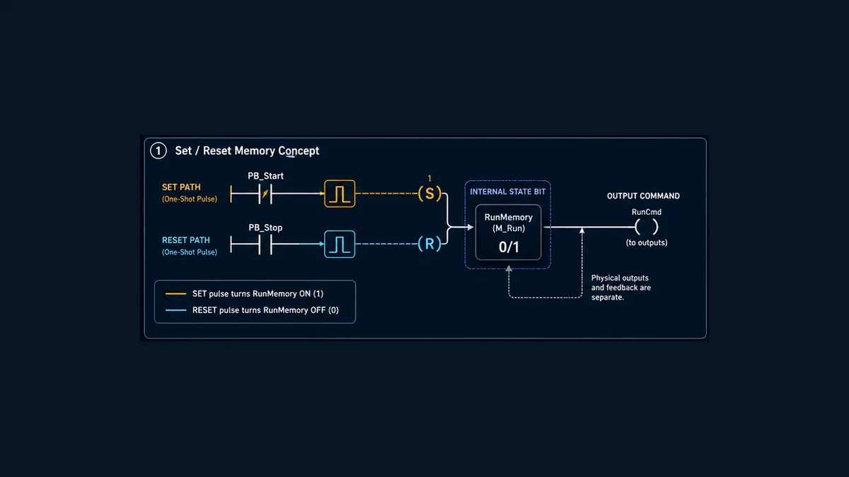
When Set/Reset is the right memory mechanism
A Set/Reset pair is useful when an event should change a state and that state must remain unchanged until a different event occurs. Examples include an accepted run request, an alarm acknowledgement flag, a completed-step marker, a manual selection or a mode request. The requirement should naturally read “set when this happens; reset when that happens.”
It is not automatically the best way to implement every Start/Stop circuit. Compare the alternatives before adding retained state:
| Mechanism | How the next value is produced | Strong fit | Typical failure mode |
|---|---|---|---|
| ordinary coil | destination equals the evaluated rung result each intended execution | direct command, permit, derived status | duplicate coils make the final writer hard to see |
| seal-in branch | ordinary coil plus its own contact maintains a true path | simple maintained request with a visible stop constraint | hidden bypass around the stop/permit branch |
| Set/Reset pair | separate one-sided writes preserve previous state when neither executes | event-owned Boolean state with explicit priority | scattered writers, undefined simultaneous commands |
SR/RS state block |
one block calculates state with a documented dominant input | centralized state and visibly chosen priority | assuming every vendor names or initializes it identically |
| enumerated state machine | one state variable and controlled transitions | sequences with three or more mutually exclusive states | transitions distributed across code or incomplete recovery |
Use an ordinary coil when the requirement is simply Output = Conditions. Use a seal-in circuit when the holding path and stop constraint are easiest for technicians to see in one network. Use Set/Reset when the events are separated in time but can still be collected in one owner. Use a state machine when multiple steps, faults, retries or recovery states make a Boolean too small to explain reality.
The contacts and coils guide explains basic power flow and seal-in behavior. The comprehensive ladder tutorial covers scan execution and program structure. This page owns the narrower question: how to design, trace and prove a Set/Reset state.
Freeze the state contract before writing ladder
“Latch this bit” is not a complete requirement. A reviewable contract identifies the state, every request, priority, storage, restart and consumer.
| Contract question | Conveyor teaching answer | Why it matters |
|---|---|---|
| what does the bit mean? | RunMemory = ordinary run request accepted |
prevents HMI text such as “Motor Running” from overstating it |
| who may set it? | qualified local or HMI start pulse through arbitration | blocks direct writes from multiple interfaces |
| who may reset it? | stop, disallowed mode or approved initialization | makes recovery and mode changes visible |
| what if both are true? | Reset wins | removes rung-order ambiguity |
| must Set be an edge? | yes for this teaching design | avoids a held Start immediately reasserting state after Reset clears |
| must Reset be an edge? | no; it remains level-sensitive | a held Stop keeps the state clear |
| who writes the state? | one arbitration routine in one task | gives cross-reference a single authoritative writer |
| what happens at cold start? | clear until a new accepted operator request | prevents an assumed automatic restart |
| is storage retentive? | do not assume; configure and test target behavior | instruction memory and power-cycle persistence are different topics |
| what consumes it? | command arbitration and honest HMI request status | keeps state, command and feedback separate |
Name states for meaning, not for an instruction. RunMemory, StartAccepted or AlarmAcknowledged communicates more than Latch1. Name requests with an action and source: LocalStartPulse, HmiStartPulse, StopRequest, ModeResetRequest. An online technician should be able to read the cross-reference without reverse-engineering addresses.
The downloadable register includes storage, task, HMI, feedback and safety ownership. Fill the project column before implementation and attach controlled evidence after testing.
Build exactly one state writer
The strongest Set/Reset pattern does not place a Set coil near one input, a Reset coil in a fault routine, another Reset behind the HMI and a second Set in the sequence. It collects requests, resolves them once and writes once.
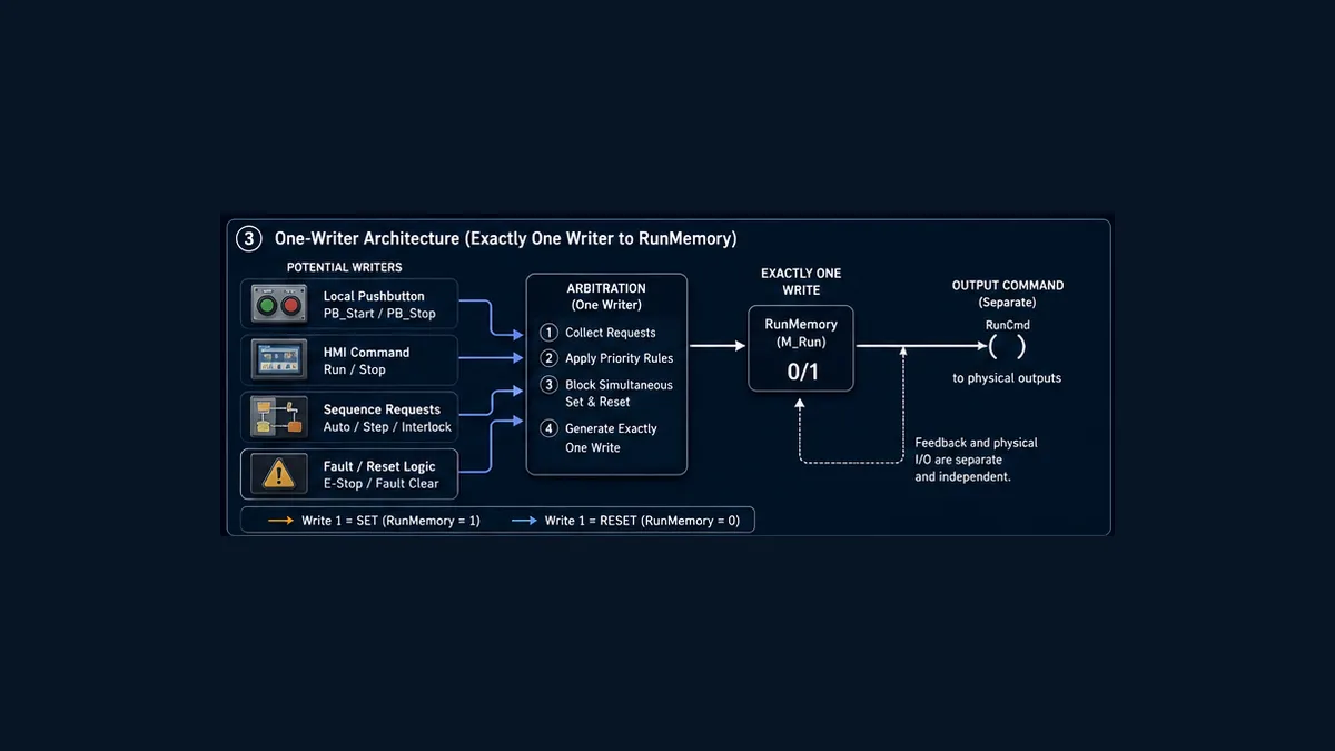
Use three layers:
- Request collection converts raw controls and remote commands into named, qualified requests. It owns debounce, HMI handshake, source authorization and edge detection.
- State arbitration applies the truth table and writes
RunMemoryonce. - Command/output mapping combines remembered intent with current mode, permits and ordinary faults, then maps the reviewed command to an output. Feedback independently reports what the machine did.
A vendor-neutral reset-dominant outline is:
SetReq   := LocalStartPulse OR HmiStartPulse OR SequenceStartPulse;
ResetReq := StopRequest OR ModeNotAllowed OR InitializationClear;

IF ResetReq THEN
    RunMemory_Next := FALSE;
ELSIF SetReq THEN
    RunMemory_Next := TRUE;
ELSE
    RunMemory_Next := RunMemory;
END_IF;

RunMemory := RunMemory_Next;    // the only state write
RunCmd := RunMemory
          AND AutoMode
          AND ProcessPermits
          AND NOT OrdinaryFault;
Run Structured Text in the simulator
This is executable logic as a Boolean design, but it is deliberately not drop-in code for a named PLC. Map data types, task execution, edge instructions, initialization and output ownership to the exact target. Do not paste a physical output address into the teaching outline.
Why the one-writer rule matters
Many PLCs execute logic in a defined order, so two writes can be legal and deterministic. They can still be difficult to maintain. A value seen online at the end of a cycle may have been set, cleared and set again before the output update. Cross-task writes can add preemption or asynchronous producer behavior. Aliases, HMI writes and produced/consumed data can hide ownership outside the visible routine.
A one-writer architecture turns “which rung won?” into “which request was accepted?” That is easier to trace, test and explain. Multiple inputs to one block are not multiple state writers; they are request producers. The distinction is architectural, not cosmetic.
Live mini-lab
Try it: press START, then STOP
A stop-dominant seal-in rung: START latches the motor output through its own contact, and STOP breaks the circuit.
Watch the output lamp: it stays on after START until you press STOP.
Free · no signup to try · runs in your browserOpens plcsimulationsoftware.com — same team
Understand scan-by-scan behavior
The PLC does not evaluate a Set/Reset diagram as a timeless electrical schematic. Instructions execute within tasks and routines. The result visible after a scan depends on the previous state, sampled or refreshed inputs, instruction order, calls that actually executed, and any later writer.
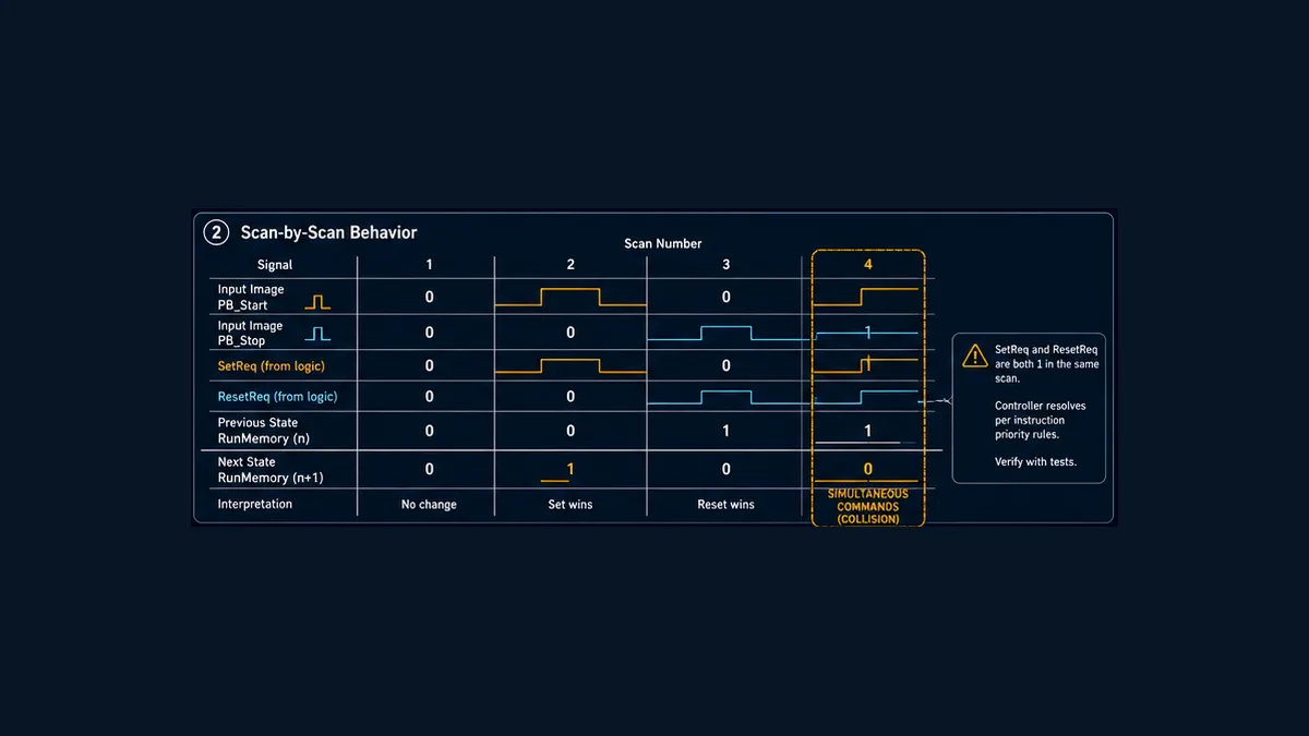
For the reset-dominant equation, this eight-scan example is deterministic:
| Scan | SetReq | ResetReq | Previous | Next | Interpretation |
|---|---|---|---|---|---|
| 1 | 0 | 0 | 0 | 0 | idle holds |
| 2 | 1 | 0 | 0 | 1 | set accepted |
| 3 | 0 | 0 | 1 | 1 | memory holds after pulse |
| 4 | 0 | 0 | 1 | 1 | no request, still set |
| 5 | 1 | 1 | 1 | 0 | simultaneous requests; Reset wins |
| 6 | 1 | 0 | 0 | 1 | a new Set can be accepted after Reset clears |
| 7 | 0 | 1 | 1 | 0 | Reset clears state |
| 8 | 0 | 0 | 0 | 0 | clear state holds |
If a held Start remains true rather than becoming a pulse, scan 6 may re-set automatically as soon as the Reset request disappears. That might be correct for a maintained mode selector and dangerous or surprising for a momentary start command. Decide whether each request is edge-sensitive or level-sensitive.
Edge-sensitive Set, level-sensitive Reset
The teaching pattern converts Start into a rising-edge pulse but leaves Stop as a level request. That means:
- pressing Start once requests one transition;
- holding Start does not continuously demand a set;
- holding Stop keeps Reset true;
- releasing Stop does not itself restart the state; and
- a new Start edge is needed after the reset condition clears.
An edge detector also has state. Its history can behave differently when a routine is skipped, disabled or first called with the input already true. Define first-call behavior and test it on the target. A pulse shorter than the PLC input sampling or task interval may never be observed; a one-shot instruction cannot recover an event that never entered its execution context.
Simultaneous commands must be observable
Do not hide simultaneous Set and Reset requests merely because the chosen priority makes the output deterministic. Create a diagnostic such as SetResetConflict, event counter or timestamp when both are true. Repeated collisions often reveal a stuck button, conflicting HMI/sequence ownership, mode-transition race or incomplete reset handshake.
For a set-dominant design, the Boolean equation is:
NextState = SetRequest OR (PreviousState AND NOT ResetRequest)
The only changed row is Set=1, Reset=1, where the next state becomes 1. Use set dominance only when the requirement says that is the safe and correct business behavior. Instruction order is an implementation detail; priority is a requirement.
Set/Reset, seal-in and ordinary coil example
Three ladder designs can appear to solve the same Start/Stop problem but have different contracts.
| Event | ordinary coil from Start | seal-in branch | Set/Reset state |
|---|---|---|---|
| Start pressed | true while rung true | becomes true and holding contact closes | Set writes true |
| Start released | false | stays true while stop path permits | no Set/Reset write; previous true holds |
| Stop active | false if included | constraining path opens and coil writes false | Reset writes false |
| neither active | false | depends on held contact and permits | preserves previous state |
| both active | Boolean rung arrangement decides | stop-path placement decides | declared priority or execution order decides |
| routine not called | no instruction execution | no instruction execution | no instruction execution |
| power cycle | target/storage/startup dependent | recalculated after startup execution | target/storage/startup dependent |
The phrase “seal-in coil” sometimes gets used for both a self-holding ordinary coil and a latch instruction. They are not the same. A seal-in branch continuously re-establishes the ordinary coil result while its holding path is true. A Set instruction makes a one-sided write and otherwise leaves the destination unchanged. That difference is crucial when a routine stops executing or when another writer targets the bit.
Cross-vendor instruction mapping
Map the behavioral contract, then verify the vendor instruction. Do not translate by symbol shape alone.
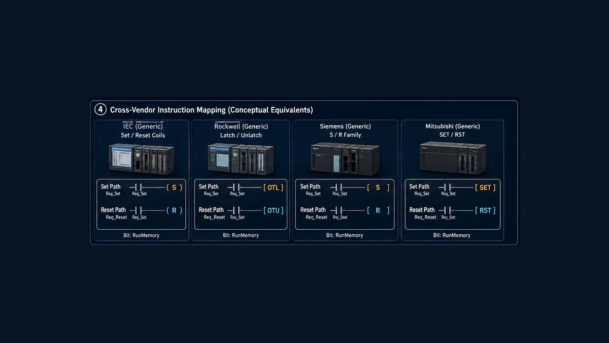
| Platform family | Common surface | Confirmed execution idea | Target checks |
|---|---|---|---|
| IEC-style editors | Set/Reset coils; SR or RS block where supported |
true Set or Reset input makes the corresponding state write; block name or input order commonly communicates dominance | language profile, block/coil priority, initialization, retain attribute |
| Rockwell Logix | OTL / OTU |
current v38 help says OTL sets (latches) the data bit when rung-condition-in is true; OTU clears it when true | supported controller/data type, aliases, tasks, prescan/restart and paired ownership |
| Siemens STEP 7 / TIA Portal | Set/Reset coils and S/R-family operations depending on target/language | separate Set and Reset state operations are available in ladder; exact coil/block behavior belongs to the target help | CPU generation, LAD dialect, block choice, network order, optimized data and startup OB policy |
| Mitsubishi MELSEC iQ-F | SET / RST |
current FX5 manual says true SET turns the device on, true RST turns it off, and false commands do not change it | permitted devices, program order, latched device area and initial-device settings |
| CODESYS Ladder | Set coil / Reset coil | current help says a TRUE arriving at Set retains TRUE and a TRUE arriving at Reset retains FALSE while the application runs | runtime version, retain/persistent storage, task order and multiple access |
| Schneider Machine Expert | Set/Reset coils | product help documents the Set and Reset coil variants separately from an ordinary coil | controller/runtime version, task order, retain configuration and download behavior |
Mitsubishi’s current FX5 instruction manual makes the ordering issue unusually explicit: if SET and RST execute on the same output relay, the result of the instruction nearer END is output. That is useful documentation for an FX5 project, not a universal PLC rule. The same manual also says a device set by SET holds on after the execution command turns off and can be turned off by RST.
Rockwell’s OTL/OTU help similarly describes one-sided writes: OTL sets the bit on a true rung; OTU clears it on a true rung. Neither fact defines the project’s power-cycle policy by itself. Controller memory, tag configuration, program transitions and initialization logic complete that answer.
When migrating, create a mapping record with old instruction, new instruction, old task, new task, state storage, simultaneous truth table, cold/warm restart, download behavior and test evidence. A successful compile proves syntax and type consistency, not equivalent machine behavior.
Restart, retention and initialization are separate decisions
“Latched” can mean “held across scans” in a logic discussion and “retained across power loss” in a maintenance discussion. Treat them as different properties.
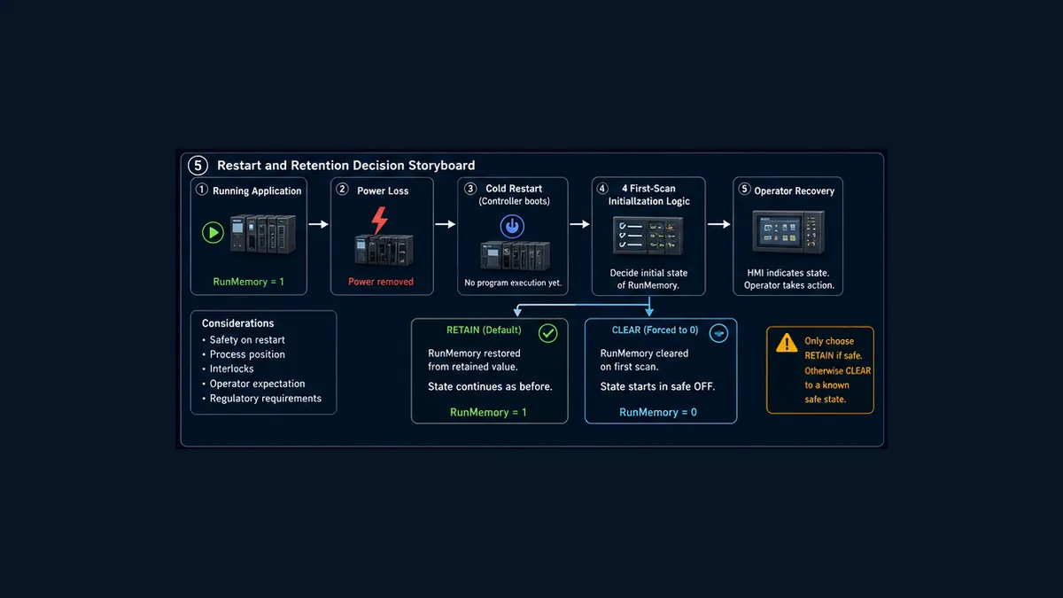
Record at least these transitions:
| Transition | Questions to answer |
|---|---|
| cold power-up | is memory restored, cleared, initialized or recalculated; can a held request set it immediately? |
| warm restart | does state survive and does the task resume with preserved edge history? |
| Program to Run | is there prescan, startup organization logic or a first-execution difference? |
| online edit | can instruction order or first-call history change while state remains live? |
| download | which values initialize, preserve or overwrite; what does the output owner do? |
| mode change | should leaving Auto clear the request or merely inhibit the downstream command? |
| communication loss | can an HMI request remain true or be replayed after reconnect? |
| routine disabled | does state intentionally hold, and what request is processed when execution resumes? |
For the conveyor teaching example, cold startup clears RunMemory, keeps RunCmd false and requires a new accepted Start after modes and ordinary permits are valid. That is a teaching policy, not a universal recommendation. A process phase marker might legitimately need retention; a motion or heater request may require conservative clearing. The project’s risk assessment and operating specification decide.
Never use a first-scan reset as a substitute for understanding storage. It can create its own order dependency: an earlier Set followed by a later initialization clear will behave differently from the reverse order. Centralize initialization within the same state owner or use the target’s documented initialization facilities, then test cold, warm, download and mode-transition cases separately.
Keep request, command, output and feedback honest
One Boolean cannot truthfully mean “operator asked,” “logic commanded,” “output energized” and “machine running.” Use separate states:
| Signal | Meaning | Typical source |
|---|---|---|
RunMemory |
ordinary run request accepted | Set/Reset state owner |
RunCmd |
current command after mode, permits and ordinary faults | command arbitration |
OutputPoint |
PLC output image or mapped command | I/O owner |
RunFeedback |
contactor, drive or process confirms running | qualified field input/network status |
StartRejected |
request arrived but requirements were not met | arbitration diagnostic |
FeedbackTimeout |
command and physical feedback disagreed beyond allowed time | diagnostic timer/state |
This separation answers common field questions. If RunMemory=1 but RunCmd=0, inspect modes and permits. If RunCmd=1 but the output image is false, inspect output ownership and later writes. If the output is true but feedback is false, inspect module, wiring, final element and process response under authorized procedures. Do not “fix” a feedback problem by adding another latch.
An HMI should write a request or handshake, not the internal state bit or physical output directly. A robust pattern distinguishes command received, command accepted or rejected, resulting state and physical feedback. Clear or acknowledge the request using a documented handshake so a stale true value does not replay after reconnection.
Troubleshoot a Set/Reset bit systematically
When a latch appears stuck, avoid random online toggling. Start with the exact state transition and final writer.
| Symptom | Likely causes | Evidence to collect |
|---|---|---|
| bit never sets | Set request not sampled, edge history already true, request blocked, writer skipped | raw input, qualified request, writer-executed flag, task trace |
| bit sets for one scan then clears | Reset also true, later Reset/writer, initialization or mode reset | simultaneous flag, full cross-reference, ordered trace |
| bit will not reset | Reset request not qualified, routine skipped, wrong destination/alias, later Set wins | reset path, destination identity, scheduler and post-writer value |
| bit re-sets after Stop releases | Start is held level, HMI request stale, sequence still requests Set | raw versus pulse requests and command handshake |
| power-up starts unexpectedly | restored state, held input, startup logic or downstream command lacks inhibit | cold-start trace and retained-memory configuration |
| HMI differs from PLC | HMI writes a different tag, stale communication, display uses command/feedback incorrectly | tag path, quality/age, request-command-feedback values |
| output off while state is set | ordinary permit/fault removes RunCmd, separate output owner clears it |
state-to-command trace and output cross-reference |
| state changes with no visible rung | HMI/remote write, alias, another task, produced data, force or online edit | full project cross-reference, audit log and force status |
| collision counter increases | competing sources, stuck controls, poorly sequenced mode/fault reset | source-attributed request events and timestamps |
Use an ordered diagnostic workflow:
- Identify the exact tag, scope, alias and data type.
- Export or inspect every writer, including HMI/communications and forces.
- Confirm the owning task and routine execute when the symptom occurs.
- Trace raw inputs, qualified Set/Reset requests, previous/next state and writer execution together.
- Check simultaneous-command priority and actual instruction order.
- Separate remembered state from command, output and feedback.
- Reproduce the relevant startup, mode or communication transition in an authorized test environment.
- Compare the observed trace with the approved truth table before changing logic.
Forces, online edits and downloads can move real equipment. Follow site authorization, change control, hazardous-energy control and electrical safe-work procedures. Use simulation or isolated training hardware for logic learning; it cannot prove field wiring, final-element behavior or safety performance.
Acceptance testing: prove the state, not the screenshot
The 20-test matrix includes ordinary, simultaneous, held-input, missed-pulse, first-scan, cold/warm restart, skipped-routine, mode, HMI, later-writer, feedback-mismatch and permit-loss cases.
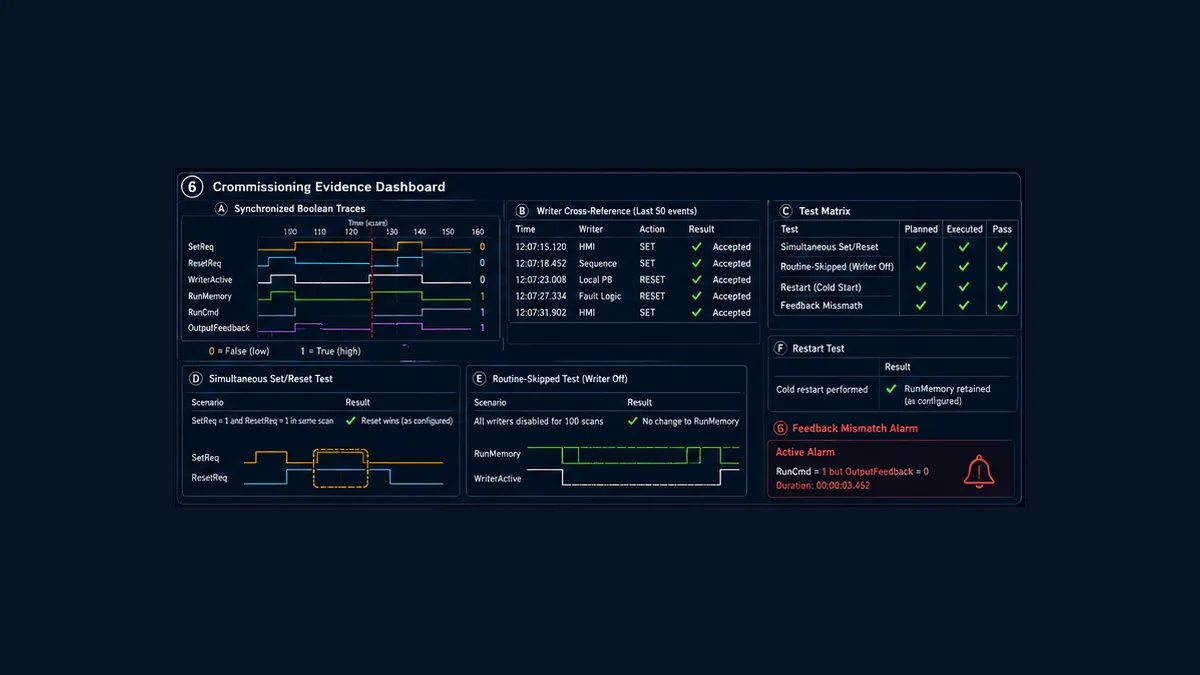
For each test, retain:
- controller and firmware, engineering software and project checksum/version;
- task/routine and relevant execution rates;
- initial state and input/request preconditions;
- timestamped Set, Reset, conflict, previous/next state and writer-executed signals;
- command, output image and physical feedback where the test reaches hardware;
- expected versus observed result and deviation reference; and
- reviewer, date, environment and authorization.
Simulation is valuable for the truth table, held inputs, conflict priority, skipped execution and many restart policies. It does not validate physical input pulse capture, I/O update timing, communication recovery, electrical circuits, contactor/drive response, process feedback or a safety function. Re-run the appropriate acceptance subset on the exact target and, when authorized, at the field boundaries.
To practise the request/state/command/feedback trace and inject simultaneous or missing-feedback cases, use the PLC ladder-logic simulator. Ownership disclosure: PLC Programming operates PLC Simulation Software. It is a browser-based vendor-neutral learning environment, not a Rockwell, Siemens, Mitsubishi, CODESYS or Schneider runtime and not a substitute for target compilation, hardware commissioning or safety validation. Current scope and limitations are published in its versioned product facts.
Frequently asked questions
What is Set/Reset in PLC ladder logic?
It is a state pattern in which a true Set request writes a Boolean to 1, a true Reset request writes it to 0, and neither request leaves the previous value unchanged. Exact symbols, priority and restart behavior are platform-specific.
What is the difference between Set/Reset and a normal output coil?
An ordinary coil normally writes both true and false according to its rung whenever it executes. A Set or Reset instruction makes a one-sided write when its condition is true and otherwise preserves the destination.
What is the difference between Set/Reset and a seal-in circuit?
A seal-in uses an ordinary coil and its own contact to keep the rung true. Set/Reset stores state through separate one-sided writes. They may produce similar operator behavior but differ under skipped execution, multiple writers and migration.
Which wins if Set and Reset are true together?
The approved design must say. A reset-dominant equation makes Reset win; a set-dominant equation makes Set win. Separate instruction pairs may depend on execution order. Verify the exact target and test both previous states.
Is Reset always safer than Set priority?
No universal priority is automatically safe. Reset dominance is often understandable for ordinary Stop behavior, but the machine requirement and risk assessment determine the correct state. Safety functions require their own validated architecture.
What do OTL and OTU mean?
In Rockwell Logix ladder, OTL is Output Latch and OTU is Output Unlatch. Current Studio 5000 help describes OTL as setting the data bit on a true rung and OTU as clearing it on a true rung.
What do SET and RST mean in Mitsubishi PLCs?
In the current MELSEC iQ-F FX5 instruction manual, true SET turns the specified device on and true RST turns it off; a false execution command does not change the state. If both target one output relay, documented program order determines the result.
Does a Set bit survive a power cycle?
Not because it is a Set bit. Across-scan memory, retained device/tag configuration, cold/warm restart, battery/nonvolatile storage, download behavior and initialization are separate platform decisions.
Should Start be edge-triggered before Set?
Often, when a momentary Start should request only one transition. Otherwise a held Start can immediately re-set the state after Reset disappears. A maintained selector may intentionally use level behavior.
Can an HMI write the latched state directly?
It can on some systems, but a request/accept/reject handshake is easier to authorize, diagnose and test. Keep the PLC state owner authoritative and expose honest state, command and feedback separately.
Why does my PLC latch set and then immediately reset?
Common causes are a simultaneous Reset request, a later Reset or other writer, first-scan initialization, a mode-reset condition or task order. Trace every request and writer rather than watching only the final bit.
Can several routines write the same Set/Reset bit?
Many platforms allow it, but it creates order and ownership dependencies. Prefer several named request producers feeding one state writer. Confirm the entire project, HMI, communication and force cross-reference.
What happens if the Set/Reset routine is not executed?
Its instructions do not run, so the state commonly remains at its last written value while skipped. Edge history and the first resumed scan may introduce additional target-specific behavior. Test the actual scheduler.
Is a Set/Reset rung a safety circuit?
No. It is ordinary programmable control memory. Emergency stops, guards and other required risk reduction need the appropriate safety devices, architecture, diagnostics and validated lifecycle.
Sources, scope and limitations
This guide was reviewed on August 31, 2026. The current controlled manufacturer documentation for the exact CPU, firmware, editor and project remains authoritative.
- IEC 61131-3:2025, Edition 4 — programmable-controller programming languages
- Rockwell Studio 5000 Logix Designer v38 — Output Latch (OTL)
- Rockwell Studio 5000 Logix Designer v38 — Output Unlatch (OTU)
- Rockwell Logix 5000 Controllers Ladder Diagram, 1756-PM008
- Mitsubishi MELSEC iQ-F FX5 Programming Manual: Instructions, JY997D55801AB
- Mitsubishi MELSEC iQ-F manuals and current revision index
- CODESYS Ladder — ordinary, negated, Set and Reset coils
- Schneider Electric Machine Expert — Set and Reset coil behavior
- Siemens S7-1200 Easy Book — ladder and controller execution context
- OSHA 29 CFR 1910.147 — control of hazardous energy
- OSHA 29 CFR 1910.333 — electrical safe-work practices
The ladder fragments, equations, state names, tables, images and downloadable artifacts are original teaching material. They are not a compilable project, electrical drawing, risk assessment, safety program or authorization to operate, force, edit, download, rewire or test equipment. Only qualified and authorized personnel following the site’s approved requirements, change control, hazardous-energy procedures, electrical safe-work rules, manufacturer instructions and validation plan should modify an installed control system.
Now run it · free · no signup
Run a start/stop seal-in circuit yourself
Press START, watch the contactor seal in, then prove STOP drops it out in a free browser motor-control lab. No signup required to finish the lab.
Ownership disclosure: PLC Programming IO and PLC Simulation Software are operated by the same publisher.
PLC Programming IO Editorial Team
Industrial automation education, references, and software testing
The PLC Programming IO Editorial Team publishes sourced industrial-automation education and documents how material is reviewed, tested, and corrected. A team byline means the publisher is responsible for the page; it does not represent a fictional person or imply an engineering licence.
Coverage:
- • PLC programming concepts and examples
- • Vendor software tutorials and comparisons
- • SCADA, HMI, protocols, and instrumentation
- • Training, careers, and reference material
Review standard:
- • Prefer primary and official sources
- • Record software versions when material
- • Separate tested facts from estimates
- • Publish material corrections
Important scope note
This site provides education, not project-specific engineering approval. Safety, code, and compliance decisions require a qualified person with access to the actual machine and jurisdiction.