Ground Fault on a VFD: Safe Isolation and Troubleshooting
Diagnose a VFD earth or ground fault by preserving trip evidence, separating the drive from motor cable and motor, and proving the repaired boundary safely.
Review status: Reviewed against current official ABB ACS580, Danfoss FC 301/302, Siemens SINAMICS G120/G120X, Rockwell PowerFlex 520/750 and Schneider Altivar documentation plus IEC adjustable-speed-drive safety publication records and OSHA hazardous-energy requirements; exact drive, firmware, motor, cable, filter, contactor, protection, grounding system, insulation-test method/voltage/limits, energy-control procedure and repair authority require project-specific verification
Direct answer
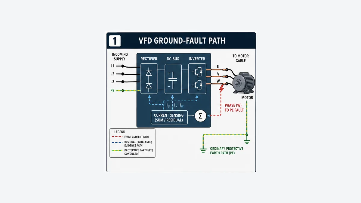
A VFD ground fault or earth fault usually means the drive detected an unintended output-current path from one or more motor phases toward protective earth, commonly in the motor cable, motor windings/terminal box or an output-side component. It can also be caused by incorrect power/motor connections, drive current-sensing/power hardware, application/configuration conditions or a documented firmware issue. The exact fault definition and threshold are product-specific.
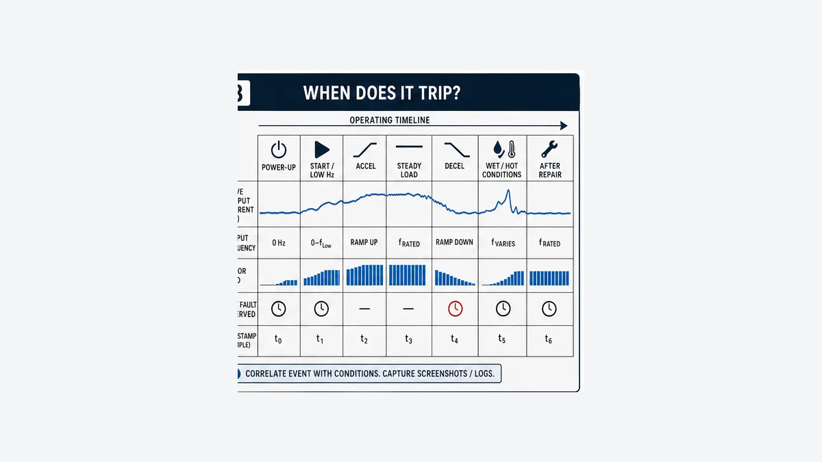
Do not repeatedly reset and restart. Capture the exact code, first occurrence, drive model/firmware, command frequency, output current, DC-bus/status values, load, temperature/moisture and whether it trips at power-up, start, acceleration, steady load, deceleration or intermittently. Then follow the site electrical-safety and hazardous-energy procedure, wait the drive's stated discharge time and verify absence of voltage with the approved method.
For insulation testing, disconnect and protect the VFD and every sensitive connected device. Never apply an insulation-resistance test through the drive. Separate the output path into drive, filter/reactor/contactor/junctions, motor cable and motor so the failed boundary is proved rather than guessed. Use only the test voltage, connections, discharge method, temperature correction and acceptance limits required by the exact drive/motor/cable manuals and asset standard. After repair, restore protective earth and all connections, inspect/verify torque as required, then prove a controlled start/load trend and a defined no-repeat monitoring period.
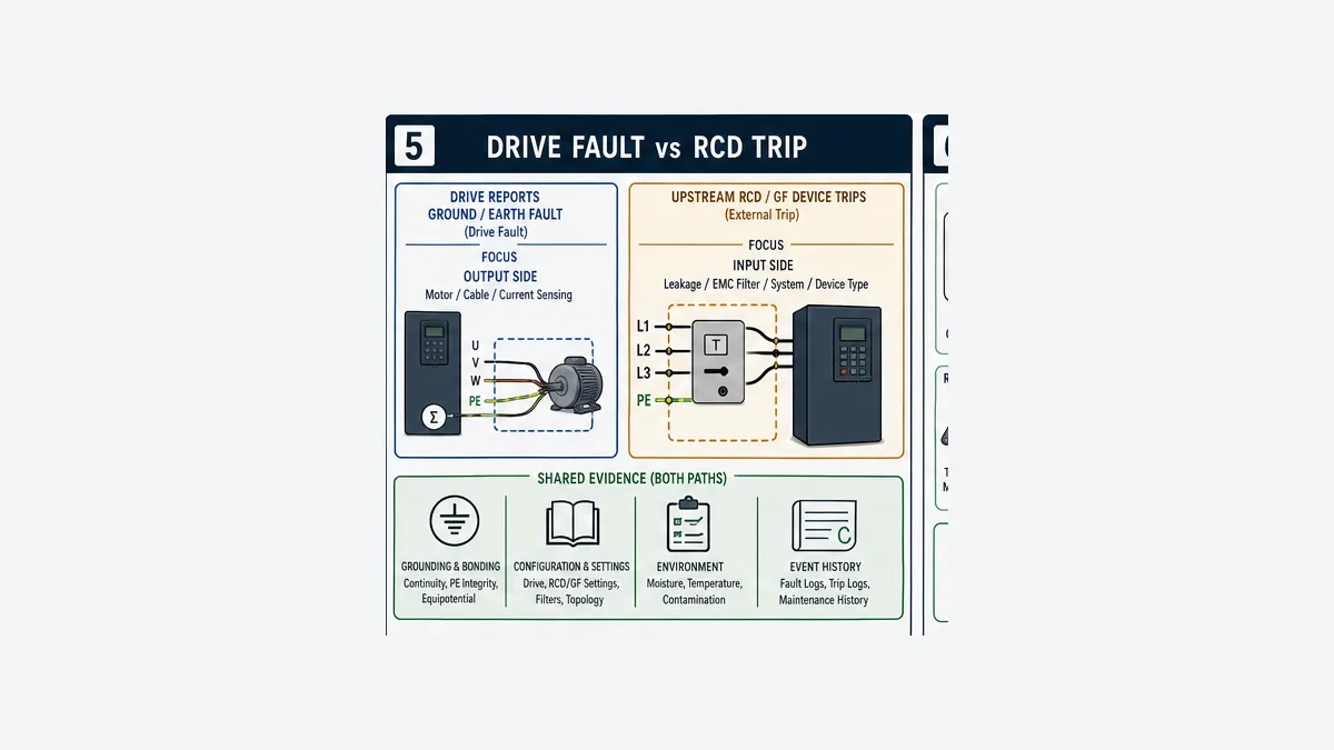
If the upstream RCD/GF protective device trips but the VFD does not report its own earth/ground-fault code, treat that as a different branch involving input-side leakage, EMC filters, cable/system capacitance, grounding topology and protective-device selection/settings. Do not assume it is the same event.
Download the VFD ground-fault evidence sheet, isolation decision register and repair acceptance matrix.
What this guide owns
This page owns one diagnostic task: isolating a drive-reported ground/earth fault or a related ground-short symptom across the VFD output path. The broad VFD fault troubleshooting guide owns the complete drive-code/DC-bus/output/thermal fault map. The VFD setup and wiring guide owns supply, motor, cable, PE/shield, EMC and physical commissioning. The PLC-controlled VFD integration guide owns run/reference/status and PLC loss recovery.
The distinction matters. A code article must be deep enough to identify the failed component and return-to-service evidence without copying generic wiring or every other drive fault.
Understand what the VFD actually detected
Residual current is not the protective-earth conductor
In normal three-phase motor operation, the instantaneous phase-current sum seen by the drive's measurement/protection model should behave within its designed limits. An unintended phase-to-earth path changes that evidence. Danfoss describes Alarm 14 as output-phase current to ground in the motor cable or motor, with current sensors comparing current going out and returning. ABB ACS580 fault 2330 describes load unbalance typically caused by an earth fault in the motor or motor cable. Product algorithms, filters, thresholds and fault names differ.
The protective-earth conductor itself is required. Removing PE to “see if the fault clears” defeats protection and is not a diagnostic method. Likewise, shield bonding, PE, signal common and network/control reference are not interchangeable conductors. Follow the exact drive and installation design.
Vendor code examples are not a universal lookup table
| Vendor/product example | Official fault surface | Officially documented direction | Important boundary |
|---|---|---|---|
| ABB ACS580 | 2330 Earth leakage | load unbalance typically caused by earth fault in motor or motor cable; check insulation and prohibited output components | 3181 separately covers wiring/earth fault such as input power connected to motor terminals |
| Danfoss FC 301/302 | Alarm 14 Earth (Ground) Fault | output-phase current to ground in cable or motor; current-sum deviation too large | exact adapter/drive configuration and installed manual still govern |
| Siemens SINAMICS G120X/G120 | F30021 Power unit: Ground fault | check power cable, motor and power-unit/current-transformer/brake-related branches as documented | fault value/remedy depend on exact power module and firmware |
| Rockwell PowerFlex 750 | Event 13 Ground Fault | product manual states a current path to earth above its specified threshold; check motor and output wiring | do not copy the threshold to another PowerFlex family |
| Rockwell PowerFlex 525 | F013 Ground Fault surfaces | check exact current manual/support plus firmware/release history | Rockwell release notes record corrected nuisance F013 conditions for earlier firmware/configurations |
| Schneider Altivar Process | SCF3 Ground Short Circuit | output earth fault; motor/cable insulation and product diagnostics are branches | no-motor/IGBT tests require exact-product steps and qualified authority |
This table is an orientation map, not authorization to change a fault threshold, disable monitoring, run open-circuit or perform a high-voltage test. Record catalog/frame/firmware and open the matching manufacturer document before action.
First decision: drive fault or upstream protective-device trip?
| Observed event | First evidence boundary | Typical branches to verify | Do not assume |
|---|---|---|---|
| drive reports earth/ground fault | drive fault history and inverter output path | motor, motor cable, output components, connections, drive sensing/power stage, configuration/firmware | upstream protective device necessarily operated |
| upstream RCD/GF device trips | protective device identity/pole coverage/type/settings and input/system current paths | EMC/RFI filter leakage, cable capacitance, multiple drives, grounding system, transient/steady leakage, device suitability | motor insulation is automatically the cause |
| both operate | timestamps and which detected/cleared first | real output fault reflected upstream, protection coordination, multiple paths | two logs prove one mechanism without time evidence |
| breaker/fuse trips without either code | overcurrent/short-circuit/coordination branch | supply fault, rectifier/power stage, wiring, fault duty/protection | “ground fault” because the machine frame is earthed |
Rockwell's current PowerFlex 520 manual states that if a system ground-fault monitor/RCD is used with that product, only Type B adjustable devices should be used to avoid nuisance tripping. That is exact-product guidance, not permission to replace or reconfigure protection universally. Determine the installation's grounding system, drive/filter arrangement, applicable electrical rules and protective-device requirements through qualified design.
Capture evidence before reset erases the pattern
Record the exact event identity
Use the downloadable evidence sheet. At minimum capture:
- asset/equipment ID and machine/process state;
- drive manufacturer, exact catalog/frame, serial if required, firmware and option/filter modules;
- full fault code, subcode/fault value, sequence, first/secondary faults and drive reaction;
- command source, command frequency/reference, actual frequency/speed, output current/torque and DC-bus value where available;
- time since start plus whether the event was at power-up, start, acceleration, steady load or deceleration;
- motor catalog/nameplate, connection, temperature/load and recent maintenance;
- motor-cable type, length, route, terminations, joints/junctions, output reactor/filter/contactor and recent changes;
- environment: rain/washdown/condensation, humidity, dust/contamination, temperature and time of day; and
- upstream protective-device state, neighboring-drive behavior and photographs/traces.
Timing narrows the branch without proving it
| Fault timing | Useful first branches | Alternative that prevents overconfidence |
|---|---|---|
| immediately at power-up before run | incorrect input/output wiring, drive power/sensing hardware, stored code/sequence | verify whether the fault is active or only historical |
| on Start at very low frequency | motor/cable/output component, motor connection, drive detection/control condition | inspect exact firmware notes and configuration |
| only during acceleration/high current | marginal insulation under stress, cable/output components, load/current and drive power stage | distinguish ground fault from overcurrent and motor data issues |
| steady load after warming | temperature-dependent motor/cable insulation, contamination/moisture, connection or drive hardware | capture winding/cable/environment temperature and time |
| deceleration | cable/output path plus regeneration/DC-bus/stop behavior | preserve the first code; overvoltage may be separate |
| rain/washdown/overnight | junction box, conduit, gland, cable/motor moisture and contamination | prove rather than drying/resetting away evidence |
| after cable/motor/contactor/filter work | wrong termination, damaged insulation, incorrect component/location or loose foreign strand | inspect against approved drawings and torque procedures |
Resetting can be part of a controlled test after cause/evidence and authorization are established. It is not the first diagnostic step and must not trigger automatic restart.
Establish safe isolation before opening the output path
VFDs contain stored DC-bus energy after incoming power is removed. The exact wait time, voltage-indicator/check points and verification method come from the drive manual and site electrical-safety program. An HMI Stop, PLC output false, STO state, open run permissive or drive keypad OFF is not hazardous-energy isolation.
OSHA 29 CFR 1910.147, in its jurisdiction and scope, requires an energy-control program and procedures to prevent unexpected energization/startup or release of stored energy during servicing. It requires isolation and verification before work. Electrical work may invoke additional requirements. Apply the employer's authorized procedure and qualified-person rules.
Before disconnection or testing:
- place process/equipment in the approved state and notify affected people;
- identify all incoming, regenerated, shared, bypass, control, heater/brake and mechanically stored energy sources;
- perform the documented shutdown, isolation and lockout/tagout steps;
- wait at least the product-stated capacitor-discharge interval;
- verify absence of voltage with the approved instrument/method and required live-dead-live proof;
- record/label every conductor, link, shield, PE and optional output component before removal; and
- control motor/process movement and induced/backfed energy as required.
Do not rely on the drive display going dark.
Live mini-lab
Try it: press START, then STOP
A stop-dominant seal-in rung: START latches the motor output through its own contact, and STOP breaks the circuit.
Watch the output lamp: it stays on after START until you press STOP.
Free to start · runs in your browserOpens plcsimulationsoftware.com — same team
Divide the drive, cable and motor boundary
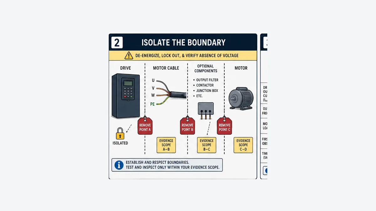
The useful boundaries are:
| Boundary | Visual/mechanical evidence | Electrical/test evidence after authorized isolation | Decision |
|---|---|---|---|
| drive output terminals/power module | contamination, damage, loose/foreign strands, correct U/V/W versus input | exact product diagnostics/service checks | remain in service, service/repair or replace under authority |
| output reactor/dV-dt/sine filter | correct product, connection, overheating, contamination | manufacturer-prescribed winding/insulation checks | repair/replace component or continue |
| output contactor/junction/connector | switching history, contact/termination damage, water ingress | isolated section continuity/insulation and contact inspection | correct control/location/termination or replace |
| motor cable | route, crushing, gland, abrasion, joints, water/chemicals | each conductor-to-PE and conductor relationships per cable/asset method | repair/replace exact segment |
| motor terminal box/leads | moisture, carbon tracking, loose links, contamination, damaged leads | terminal/lead/winding insulation and resistance balance per motor method | clean/dry/repair/reconnect or shop test |
| motor windings | overheating, contamination, bearing/process evidence | motor-manufacturer/asset-standard insulation and winding diagnostics | repair/recondition/replace or continue investigation |
Optional output contactors, filters and junctions are not invisible links. Switching a contactor on the VFD output while the inverter is operating can be prohibited or damaging depending on the product/application. Capture its sequence and physical condition.
Perform insulation testing without testing through the drive
Why disconnection is non-negotiable
ABB's ACS580 hardware manual explicitly says not to make voltage-tolerance or insulation-resistance tests on any part of the drive because testing can damage it, then gives a separate method for checking motor and motor-cable insulation. Schneider's official ground/short-circuit guidance likewise says the motor must be disconnected from the drive before a megohmmeter test. Treat connected output filters, surge devices, contactors, sensors, encoders, brakes and monitoring hardware as components with their own test boundaries.
Never assume that opening an output contactor has isolated every path. Verify the actual drawing and terminal condition. Remove/secure test leads and discharge tested assets as required before reconnection.
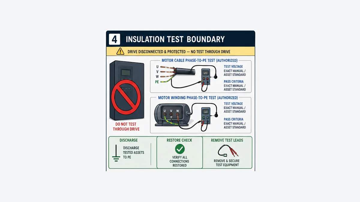
Record the complete test, not only “megger good”
| Record field | Why it matters |
|---|---|
| asset and isolated scope | distinguishes cable, motor leads, windings and combined circuit |
| disconnected/protected equipment | proves drive/filter/electronics were not exposed |
| instrument ID/calibration/condition | supports measurement traceability |
| test voltage and duration | insulation resistance depends on the applied method |
| conductor/phase and connection | identifies asymmetry and exact failure path |
| temperature and environment | resistance changes with temperature and moisture/context |
| initial/final/time-series result | supports the asset standard's decision method |
| discharge and restoration steps | prevents stored test charge and missed reconnection |
| acceptance source/revision | avoids invented universal megohm pass limits |
The correct test voltage is not universally 500 V, 1 kV or the motor line voltage. The correct limit is not universally one megohm, infinity or one value copied from a forum. Cable type/length, motor voltage/design/age, insulation system, temperature and maintenance standard matter. A handheld DMM resistance check can find a hard short but cannot replace the required insulation-resistance test.
Separate cable and motor when the combined circuit fails
Testing the combined motor+cable circuit can confirm a problem exists, but not what to replace. Disconnect at the motor terminal box under the approved procedure, then test the cable and motor as separate scopes. Preserve link positions and motor connection. Inspect for moisture, conductive dust, carbon tracking, damaged insulation, overlong/poorly stripped strands, sharp gland edges, crushing, overheated lugs and contaminated joints.
If readings improve after drying, that is evidence of an environmental mechanism—not automatically a permanent repair. Identify ingress, sealing, heater/drain/ventilation and contamination control as appropriate to the equipment design.
Do not overlook drive, configuration and firmware branches
A motor/cable fault is common, but the diagnostic must not stop at probability.
Fault persists with the entire output path disconnected
Do not energize or run the VFD with no motor unless the exact manual/support procedure authorizes that product/configuration and qualified people have established a safe test. Schneider publishes product-specific no-motor/IGBT diagnostic steps for some Altivar families; those steps include parameter changes and conditions that do not transfer to another drive.
If a fault is active with the output path disconnected or exact insulation/visual evidence is sound:
- verify input and motor terminals were not interchanged;
- inspect output terminals and internal/external power structure within authorized service scope;
- run only the product's built-in transistor/current-sensor diagnostics as documented;
- compare exact firmware and product advisories/release notes;
- verify motor data/control mode, switching frequency, cable length and approved output component requirements without randomly changing them; and
- escalate to the manufacturer/qualified drive-service provider with the evidence pack.
Firmware evidence can prevent a false component diagnosis
Rockwell's official PowerFlex 525 release history records several corrected F013 nuisance conditions in earlier firmware, including specific 415 V, fast acceleration/deceleration or wake/sleep contexts. That does not prove a current F013 is software. It proves catalog and firmware belong in the evidence register before motor, cable or drive hardware is condemned. Update decisions require compatibility, change control, backup, test and the official release/upgrade process.
Do not tune away protection
Reducing switching frequency, changing motor-control mode, adding an output reactor/filter or adjusting cable/application configuration can be legitimate manufacturer-prescribed design corrections. Disabling ground-fault monitoring or weakening protection merely to keep running is not troubleshooting. Understand why the selected change is valid, record the baseline and verify motor performance/thermal/EMC/protection effects.
Worked example: fault during damp morning acceleration
This example is hypothetical and deliberately uses categorical results; apply exact asset procedures.
Symptom: A conveyor VFD reports its product-specific ground/earth-fault code 4–8 seconds after Start, usually on cool damp mornings. A reset sometimes lets the drive run later in the day. No upstream protective device trips.
Evidence before isolation
| Evidence | Observation | Diagnostic value |
|---|---|---|
| first fault | drive ground/earth code; no earlier overcurrent code | output ground-fault branch remains first |
| timing | during acceleration at repeatable frequency band | supports stress/environment correlation |
| current | rises normally then residual/drive fault | command is not copied into diagnosis; raw trend retained |
| environment | overnight washdown/condensation; junction low point | moisture ingress is plausible, not yet proven |
| history | event began after cable-junction repair | new termination/junction boundary has high review value |
| upstream | RCD/GF device did not operate | does not eliminate earth path; separates first branch |
Authorized isolated findings
The complete motor+cable insulation scope fails the approved criterion. After separating the motor at its terminal box, the motor passes its temperature-aware asset test while one cable phase-to-PE scope fails and changes with moisture at the repaired junction. Inspection finds damaged sealing and contamination tracking. The evidence identifies the cable/junction scope; the motor and VFD are not replaced by guess.
Repair and proof
Qualified personnel replace/repair the approved cable/junction components, correct sealing and termination, re-test the isolated cable, re-test the motor per its procedure, restore PE/shield and all links/torques, then conduct an authorized controlled start. They capture current/frequency/fault-state trends at no load/normal load as applicable and monitor through the environmental period that previously reproduced the event. The closeout updates as-built/maintenance evidence and addresses the ingress cause.
This example also shows why drying and resetting is incomplete: it could temporarily hide the symptom without repairing ingress or tracking damage.
PLC and HMI diagnostics for a VFD earth fault
The PLC cannot prove insulation resistance, but it can preserve the context that makes physical testing efficient.
| Diagnostic field | Source | Retention/use |
|---|---|---|
| raw fault code/subcode | drive cyclic/explicit data or fault relay plus service record | retain first-out before reset; do not normalize away raw code |
| fault timestamp/sequence | drive/PLC with time architecture | correlate to command, mode and process event |
| requested/actual frequency | PLC and drive | distinguish start/accel/steady/decel timing |
| output current/torque/DC bus | drive where supported | trend around event; units/scales exact |
| Running/AtReference | drive status | show response; never copied from Run command |
| source and command owner | drive/PLC | expose local/remote changes and reconnect |
| environment/process state | sensors/operations | moisture, temperature, load and washdown correlation |
| reset identity/result | HMI/PLC/drive | one authorized edge after cause decision; no automatic restart |
Do not auto-reset a ground fault into repeated start attempts. The reset action should be authorized, edge-bounded, logged and separated from Start. After reset, require the project-defined reauthorization and stopped/ready state.
VFD ground-fault symptom matrix
| Symptom | Strong first branch | Evidence that separates it | Unsafe shortcut to avoid |
|---|---|---|---|
| faults instantly when Start issued | motor/cable/output component or drive power stage | isolated visual/insulation plus exact product diagnostics | repeated resets |
| faults only above a frequency | marginal output insulation/cable effects/load or configuration | frequency/current/environment trend and isolated tests | universal frequency threshold change |
| faults after motor warms | winding/leads/terminal/cable temperature mechanism | hot/cold asset tests and temperature record | testing only when cold |
| faults after rain/washdown | ingress/contamination at motor/junction/cable | photos and separated wet/dry scope | drying and declaring fixed |
| faults after output contactor work | termination/switching/component sequence | as-built inspection and contactor event timing | switching output live to reproduce |
| combined motor+cable test fails | downstream circuit confirmed | separate at motor to localize | replacing both |
| motor passes but cable fails | cable/joint/gland route | per-phase/segment evidence | blaming drive |
| cable passes but motor fails | motor leads/terminal/windings | temperature-aware motor test/inspection | using generic pass limit |
| all isolated tests pass | drive/config/firmware/intermittent/environment branch | exact code context, product diagnostics and repeat conditions | disabling monitoring |
| upstream RCD trips, no drive code | input leakage/protective-device branch | device/time/current/topology/EMC evidence | assuming output motor ground fault |
| drive fault plus RCD trip | common real path or coordinated/multiple events | synchronized timestamps and isolation tests | treating logs as automatically causal |
| new drive also faults | common cable/motor/component/design/environment | reproduce boundary evidence and configuration comparison | installing a third drive |
Prove repair before returning to service
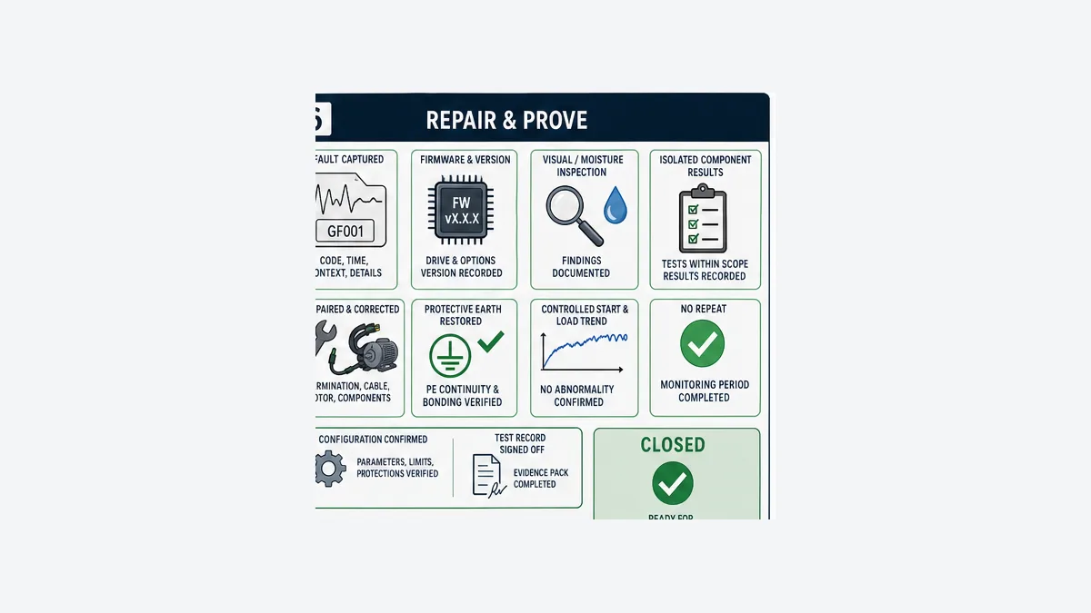
Use the downloadable repair acceptance matrix. Tailor it to the asset:
- original fault code/context and first-out are preserved;
- isolated motor, cable and optional-component results have named scopes and acceptance sources;
- failed component/root mechanism and repair are documented;
- PE/bonding, shield, links, terminals, covers, glands, cooling and torque/inspection items are restored;
- drive/motor/output-filter/contactors/configuration/firmware match approved design;
- insulation-test charge is discharged and test gear removed;
- guards/safety functions/process protections are restored and validated by their owners;
- controlled first energization/start follows the approved plan;
- frequency/current/feedback/fault evidence is captured through relevant load/transition states;
- upstream protection remains normal and no unintended leakage/fault indication occurs; and
- the asset passes the environmental/time window that formerly exposed the problem.
A single unloaded start immediately after drying is weak evidence if the original fault appeared after one hour at load or after overnight condensation.
Practise the diagnostic branch without a live motor circuit
Use the VFD simulator to rehearse first-out capture, fault timing, run/status separation, reset authorization and a drive-versus-process diagnostic sequence. A strong future troubleshooting scenario can present changing evidence as the learner isolates drive, cable and motor hypotheses—without pretending to perform a megohmmeter test.
PLC Programming IO and PLC Simulation Software share ownership. The browser lab does not generate hazardous voltage, PWM/common-mode behavior, leakage current, insulation degradation, cable capacitance, motor temperature/moisture, drive power-stage faults, actual protective-device response or safety isolation. Transfer only the reasoning method; qualified people must test the physical system.
Measure qualified CTA impression, VFD scenario start/completion, registration, paid signup and retained troubleshooting use. This page is especially product-qualified because its diagnostic workflow can inform simulator features—not just content traffic.
Frequently asked questions
What does a ground fault on a VFD mean?
It means the exact drive protection detected evidence consistent with an unintended current path toward earth/ground, typically on the inverter output through the motor cable, motor or output-side component. Definitions and thresholds vary. Preserve the code/subcode, product/firmware and operating context before testing.
Can I keep resetting a VFD ground fault?
No. Repeated automatic or manual restarts can worsen equipment damage, erase first-out context and create unexpected motion. Capture evidence, make the process safe, follow the authorized isolation/diagnostic procedure, correct the proven cause and then perform a controlled reset/start under the return-to-service plan.
Can I megger a motor while it is connected to the VFD?
No. Disconnect and protect the VFD and other sensitive electronics before insulation-resistance testing. ABB explicitly warns that voltage-tolerance or insulation-resistance tests can damage the drive. Verify the exact motor/cable/output-component procedure and restore/discharge every connection safely.
What megger voltage should I use for a VFD motor?
Use the voltage specified by the motor manufacturer, cable specification, drive/output-component instructions and the facility asset-test standard. Do not copy 500 V or 1 kV universally. Record voltage, duration, temperature, instrument, connection and acceptance source with the result.
What is a good insulation resistance for a VFD motor or cable?
There is no universal pass value. Motor voltage/design/age, cable type/length, insulation system, temperature, test duration and asset standard affect the decision. “Infinity” on one instrument is not a traceable acceptance record. Use the applicable manufacturer/maintenance criteria and trends.
How do I tell whether the motor or cable is grounded?
After authorized de-energization and disconnection from the drive, first test the combined scope if the procedure calls for it. If it fails, separate the motor at its terminal box and test motor and cable independently with named phase/conductor scopes. Inspect glands, junctions, leads and environment.
Why does the VFD ground fault happen only when it rains or after washdown?
Moisture/contamination can reduce insulation at motor terminals, cable joints, glands, conduit low points or damaged insulation. Correlate fault time with environment, then prove the exact isolated scope. Drying can hide the symptom temporarily; correct ingress, contamination and damaged materials.
Can a long motor cable cause a VFD earth fault?
Cable length and capacitance, PWM stress, switching frequency and required reactors/dV-dt/sine filters can affect an installation, and some product documentation includes cable-length/output-filter branches. Use exact drive/cable/motor limits and engineering guidance. Do not add a generic reactor or change switching frequency without a design basis.
Is an RCD trip the same as a VFD ground-fault code?
No. A drive code usually reflects its own output-current/protection model; an upstream RCD/GF device monitors a different boundary and can respond to input/filter/system leakage or a real fault. Compare device identity, timestamps and topology. Select/provide protection only through applicable electrical design and exact drive guidance.
Should I disconnect protective earth to see if the fault clears?
No. PE is a required protective path. Removing it can expose people/equipment to dangerous touch voltage and invalidates the installation. Inspect and verify PE/bonding under the authorized procedure; never use removal as a run test.
Can an output contactor cause a VFD ground or short-circuit fault?
It can contribute through damaged/contaminated contacts or terminations, wrong sequencing or switching while the inverter is active. Exact drive manuals govern whether and how output contactors are permitted. Capture contactor timing and inspect/test it as its own isolated boundary.
What should I check for PowerFlex F013 Ground Fault?
Verify exact PowerFlex family, catalog and firmware; preserve the F013 context; inspect/test the motor and output wiring under the manual; and review Rockwell product documentation/release notes. PowerFlex 525 history includes corrected firmware-specific nuisance F013 cases, so firmware context matters without disproving a real fault.
What should I check for Siemens F30021, ABB 2330 or Danfoss Alarm 14?
Use the exact manual. Siemens F30021 documentation includes power cable, motor and power-unit/current-transformer/brake branches depending on product. ABB 2330 points to load unbalance/earth fault in motor or cable and output-component checks. Danfoss Alarm 14 describes output-phase current to ground in cable or motor. Do not interchange their codes or thresholds.
Can a browser VFD simulator diagnose a real ground fault?
It can teach first-out capture, state/timing correlation, reset authorization and component-boundary reasoning. It cannot measure insulation, leakage or protective-device behavior or emulate the exact drive power stage, cable, motor and environment. Physical diagnosis requires qualified personnel, safe isolation, approved instruments and exact manuals.
Primary sources and further reading
- ABB ACS580 Standard Control Program Firmware Manual — faults 2330 Earth leakage, 2340 Short circuit and 3181 Wiring or earth fault.
- ABB ACS580-01 Hardware Manual — drive insulation-test prohibition and motor/cable insulation-check boundary; select current exact revision.
- ABB ACS580-01 current manual index — maintained hardware/firmware documentation access.
- Danfoss VLT FC 301/302 Programming Guide — Alarm 14 cause/current-sum description and product fault context.
- Siemens SINAMICS G120X Operating Instructions — F30021 cause, fault value and remedy branches for the covered release.
- Siemens SINAMICS G120C Compact Operating Instructions — product-specific F30021 remedy context.
- Rockwell PowerFlex 520-Series User Manual, September 2025 — grounding, shield and Type B adjustable RCD guidance for the covered products.
- Rockwell PowerFlex 750-Series Programming Manual — Ground Fault event definition/action and exact-family threshold example.
- Rockwell PowerFlex 525 Firmware 5.001 Release Note — corrected firmware-specific nuisance F013 contexts.
- Rockwell PowerFlex 525 support/product surface — exact product support entry including Ground Fault F13 article.
- Schneider Electric: Altivar Process SCF3 Ground Short Circuit — output earth fault, motor/cable and product-specific diagnostic branches.
- Schneider Electric: Altivar Process SCF1 troubleshooting — motor disconnected insulation testing and exact-product IGBT/no-motor diagnostic context; updated May 2026.
- Schneider Electric Altivar Process Drive Systems Installation Manual — current June 2026 installation/manual access for covered systems.
- IEC 61800-5-1:2022 publication record — electrical, thermal and energy safety requirements for adjustable-speed power drive systems.
- US OSHA 29 CFR 1910.147 — hazardous-energy control requirements in its jurisdiction and scope.
- US OSHA 29 CFR 1910.333 — selection/use of electrical work practices in its jurisdiction and scope.
Scope and limitations
This guide is a vendor-neutral evidence and isolation framework. It is not an electrical-safety procedure, energized-work authorization, lockout/tagout procedure, insulation-test instruction, drive/motor/cable design, protective-device coordination study, repair manual or permission to disable protection/run a drive open-circuit. Code names and example thresholds are product-specific.
Before work, verify drive catalog/frame/firmware/options, motor, cable, output filters/reactors/contactors/junctions, PE/shield/grounding system, upstream protection, electrical system, process/mechanical energy, exact manuals, asset test standard, applicable law and personnel qualifications. Use the approved instruments, PPE, isolation/verification and return-to-service procedure. Escalate uncertain or internal drive faults to the manufacturer or authorized repair provider.
Now run it · free to start
Learn a repeatable way to find the fault
Split a stopped machine into input, logic, output and physical response, and take the measurement that proves each stage. Practised on simulated machines. Free to start.
Ownership disclosure: PLC Programming IO and PLC Simulation Software are operated by the same publisher.
PLC Programming IO Editorial Team
Industrial automation education, references, and software testing
The PLC Programming IO Editorial Team publishes sourced industrial-automation education and documents how material is reviewed, tested, and corrected. A team byline means the publisher is responsible for the page; it does not represent a fictional person or imply an engineering licence.
Coverage:
- • PLC programming concepts and examples
- • Vendor software tutorials and comparisons
- • SCADA, HMI, protocols, and instrumentation
- • Training, careers, and reference material
Review standard:
- • Prefer primary and official sources
- • Record software versions when material
- • Separate tested facts from estimates
- • Publish material corrections
Important scope note
This site provides education, not project-specific engineering approval. Safety, code, and compliance decisions require a qualified person with access to the actual machine and jurisdiction.