What Is Alarm Management? ISA-18.2 Lifecycle Explained
Alarm management keeps operator alarms relevant, actionable and controlled through philosophy, rationalization, design, monitoring, maintenance and audit.
Alarm management is the lifecycle used to ensure each operator alarm is necessary, prioritized, understandable and actionable. It starts with an alarm philosophy, justifies alarms through rationalization, implements them with suitable setpoints and timing, monitors real performance, controls changes and audits the system. An event is not an alarm unless it requires a defined operator response.
That definition matters because an alarm list is not a history of everything that happened. A well-managed system directs an operator’s attention to an abnormal condition, states what is at risk and gives enough time to take a documented action.
Standards status in 2026
The primary process-industry references are:
- ANSI/ISA-18.2-2016, Management of Alarm Systems for the Process Industries. ISA still lists the 2016 edition as the foundational standard and publishes supporting technical reports.
- IEC 62682, the international alarm-management standard derived from the ISA work.
- EEMUA Publication 191, Edition 4 (November 2024), a practical guide to alarm-system design, management and procurement.
The older third edition of EEMUA 191 is still quoted widely online. Use the current edition selected by your organization, the adopted regulatory requirements and the site alarm philosophy. Do not paste a generic “acceptable alarms per hour” number into a specification without defining the measurement window, operating mode and consequence.
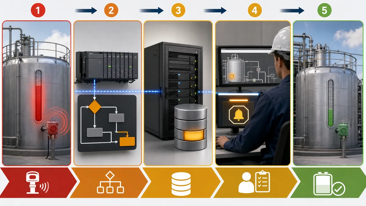
Why alarm systems fail
Most weak alarm systems are not missing software features. They have a governance problem:
- every analog limit was configured as an alarm without a required response;
- priorities reflect personal preference instead of consequence and response time;
- the same root cause produces dozens of consequential alarms;
- deadband and delays were copied without examining process dynamics;
- shelving or suppression hides alarms without ownership and expiry;
- disabled, standing and chattering alarms are not reviewed;
- a PLC or HMI change silently bypasses the master alarm database; or
- performance is measured only after an incident.
An operator facing hundreds of notifications cannot reliably distinguish the few that require immediate action. Conversely, aggressive filtering can hide a genuine abnormal condition. Alarm management balances those risks through documented decisions and evidence.
The alarm management lifecycle in practical terms
ISA’s public overview organizes the work around an alarm-management lifecycle. The descriptions below are an implementation explanation, not a substitute for a licensed copy of the standard.
| Stage | Practical deliverable | Approval evidence |
|---|---|---|
| Philosophy | Site rules, roles, priorities, KPIs and change process | Approved alarm philosophy |
| Identification | Candidate abnormal conditions from hazards and operations | Candidate register with source |
| Rationalization | Cause, consequence, action, setpoint, priority and response time | Master alarm database record |
| Detailed design | Deadband, delay, suppression, message and display behavior | Design review and configuration sheet |
| Implementation | PLC, DCS, SCADA or HMI configuration | Version-controlled release and test |
| Operation | Trained response using the implemented alarm | Operator procedure and training |
| Monitoring and assessment | Trends, floods, standing alarms and bad actors | Periodic KPI report |
| Maintenance | Repair of instruments, logic and documentation | Work history and retest |
| Management of change | Controlled modification and re-rationalization | Approved MOC record |
| Audit | Independent check of lifecycle conformance and effectiveness | Findings, owners and closure evidence |
Write the alarm philosophy first
The philosophy is the governing document for every alarm decision. It should define:
- the site definition of an alarm;
- priority categories and the method used to assign them;
- operator roles and areas of responsibility;
- alarm states, acknowledgement and return-to-normal behavior;
- rules for latching, shelving, suppression, out-of-service and maintenance;
- how nuisance, stale and duplicate alarms are handled;
- performance measures and review frequency;
- the master alarm database owner;
- management-of-change requirements; and
- acceptance, proof-test and audit responsibilities.
If two engineers can rationalize the same alarm and reach contradictory results, the philosophy is not specific enough.
Rationalization: one worked example
Consider a centrifugal pump with low suction pressure.
| Field | Example rationalization record |
|---|---|
| Tag | P-101 suction pressure low |
| Candidate cause | Inlet valve closed, blocked strainer or low vessel level |
| Undesired consequence | Cavitation and possible pump damage |
| Operator action | Verify source level and inlet path; stop P-101 if pressure does not recover |
| Time available | Determine from pump/process evidence, not a generic default |
| Setpoint basis | Pump curve, process minimum and transmitter uncertainty |
| Deadband/delay basis | Measured process noise and tolerated response delay |
| Priority | Assigned from consequence and available response time using the site matrix |
| Suppression | Suppress only in an approved state where the consequence cannot occur |
| Test | Force the cause, verify state, message, priority, timestamp, action and recovery |
The example is deliberately incomplete until the site supplies actual equipment and process evidence. A plausible number is not a design basis.

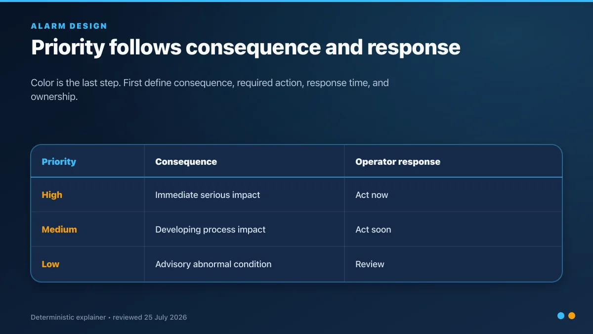
Priority is consequence plus response time
Alarm priority should not mean “the engineer thinks this is important.” A site matrix normally combines the severity of the credible consequence with the time available for operator intervention.
Use a small number of priorities that operators can distinguish. Keep the highest priority rare enough to remain meaningful. Record the rationale, because priority drift is common when configuration is changed outside the master alarm database.
Detailed alarm design
Setpoint
Choose a setpoint that gives the operator enough time to respond while avoiding routine operation. Document the source: hazard study, equipment limit, operating envelope or validated process model.
Deadband
Deadband prevents repeated transitions when a noisy process value sits around the setpoint. It must be large enough for the measured noise but small enough not to delay a genuine return-to-normal indication.
On-delay and off-delay
An on-delay can filter a brief condition that cannot cause the stated consequence. An off-delay can stabilize return-to-normal behavior. Neither is a universal cure for a bad sensor or unstable control loop.
Suppression and shelving
- Suppression by design follows an approved process or equipment state.
- Shelving is a controlled operator action, normally with reason, duration and visibility.
- Out of service is a maintenance state with authorization and compensating measures.
Do not use one label for all three; their ownership and risk are different.
Message and response
An alarm message should identify the equipment and abnormal condition. The response procedure should state the action, not merely “check equipment.” When possible, provide the related process trend and upstream/downstream context without obscuring the alarm list.
PLC, HMI and historian responsibilities
| Layer | Owns | Should not own |
|---|---|---|
| Field/instrument | Measured condition and diagnostic quality | Operator priority policy |
| PLC/DCS | Deterministic detection, process state, latching where required and safe fallback | Presentation-only behavior that changes the process consequence |
| HMI/SCADA | Alarm presentation, acknowledgement, shelving workflow and navigation | Safety function or permissive bypass |
| Historian/alarm database | Event retention, analysis and reporting | Real-time protection |
| Master alarm database | Approved design basis and lifecycle record | Uncontrolled live configuration changes |
The exact boundary depends on the platform. The important point is to maintain one authoritative design record and prove that the implemented states match it.
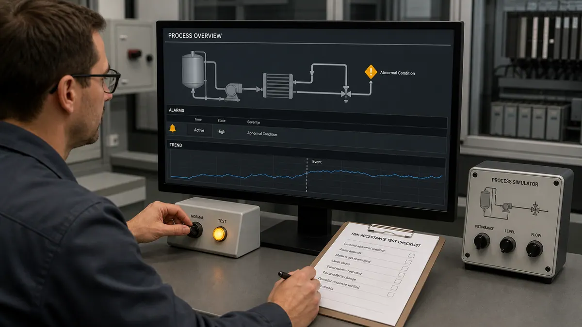
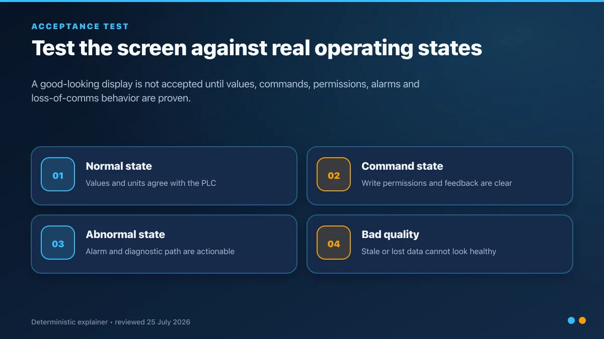
A complete alarm acceptance test
For each rationalized alarm:
- Record the application, controller and configuration versions.
- Establish the correct normal operating state.
- Introduce the defined cause using a safe test method.
- Verify the alarm appears once, with correct tag, message, priority and timestamp.
- Verify the linked process value and signal quality.
- Confirm the operator response procedure is accessible and correct.
- Acknowledge the alarm and verify the expected state transition.
- Clear the cause and verify return-to-normal behavior.
- Repeat at the deadband and delay boundaries.
- Test communications loss, bad signal quality and application restart.
- Capture evidence and reconcile the live configuration to the master alarm database.
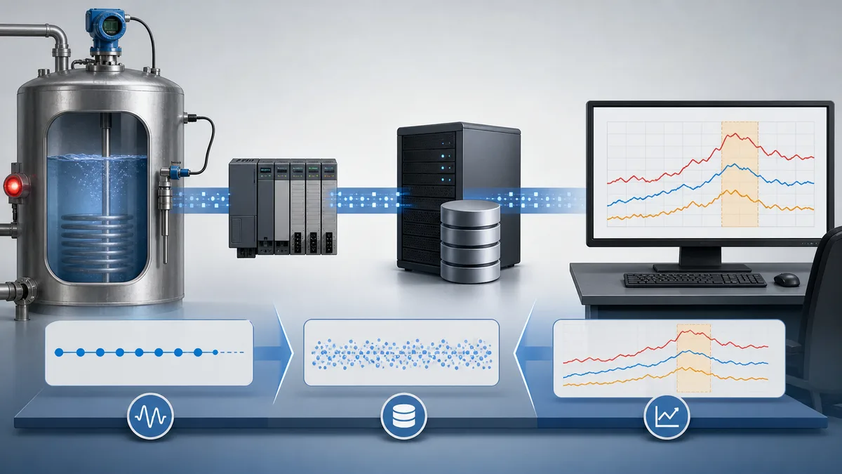
Monitor what operators actually experience
Useful reviews include:
- alarm count by operating mode and operator position;
- time spent in alarm floods;
- standing alarms at shift handover;
- chattering and fleeting alarms;
- the most frequent contributors to total load;
- shelved, suppressed, disabled and out-of-service alarms;
- acknowledgement and response timing where the site can interpret it responsibly;
- unauthorized differences between live configuration and the master database; and
- recurring alarms linked to maintenance or control-loop problems.
Do not optimize only the average. A quiet month can hide one severe ten-minute flood. Segment the analysis by startup, shutdown, grade change, trip and normal operation.
A 30-day improvement sequence
Week 1 — establish control
- approve an interim alarm owner;
- freeze uncontrolled additions;
- inventory configured, disabled and standing alarms;
- define the data extraction and measurement method.
Week 2 — remove obvious noise safely
- investigate top chattering and duplicate contributors;
- repair failed instruments and communications;
- document temporary controls through MOC.
Week 3 — rationalize one operating area
- select a bounded unit;
- complete cause, consequence, action, response time and priority;
- reconcile the approved records to the live configuration.
Week 4 — prove and sustain
- run cause-to-history acceptance tests;
- publish the first segmented performance report;
- assign recurring review and audit actions.
Practice alarm cause-and-effect safely
Before configuring a production SCADA system, build a small controller exercise with an analog process value, high alarm, deadband, on-delay, acknowledgement state and simulated signal failure. Record expected transitions before running it.
PLC Simulation Software can be used to practice the underlying PLC sequence. Disclosure: PLCProgramming.io and PLC Simulation Software have common ownership. It is a training simulator, not an ISA compliance tool, alarm historian or production HMI. It cannot rationalize an alarm, certify a safety function or replace platform acceptance testing.
Related guides:
- SCADA tutorial for beginners
- HMI design best practices
- High-performance HMI and ISA-101
- Control philosophy explained
- Cause-and-effect matrix
Limitations and safety boundary
Alarm management supports operator response; it is not a substitute for an independent protection layer, safety instrumented function, machine guard or emergency stop. Do not credit an alarm with risk reduction unless the applicable risk assessment and standards explicitly justify the complete human-response path.
This guide summarizes public information and practical engineering workflow. Purchase and apply the standards selected by your organization, jurisdiction and competent authority.
Frequently asked questions
What is the difference between an event and an alarm?
An event records that something happened. An alarm is an abnormal notification requiring a defined operator response to avoid or reduce a consequence.
What is alarm rationalization?
It is the documented review that justifies an alarm and defines its cause, consequence, action, response time, setpoint, priority, design and test basis.
Is there one acceptable alarm rate?
No single number is safe to copy without context. Establish targets through the selected standard, site philosophy, operator workload and measurement method, then examine floods and operating modes as well as averages.
Where should alarm logic live?
Deterministic detection often belongs in the PLC or DCS, while the HMI/SCADA presents and manages operator interaction. The approved master alarm database should define the behavior across both.
How often should alarms be reviewed?
Continuously monitor performance and use a site-defined periodic review and audit cadence. Review immediately after major process changes, incidents or sustained deterioration.


