S7-1500 CANopen: PN/CAN LINK Setup and Diagnostics
Connect a Siemens S7-1500 to CANopen through SIMATIC PN/CAN LINK, configure Manager or Slave mode in TIA Portal, map PDOs, control SDO access and diagnose both network boundaries.
Review status: Editorially reviewed against current Siemens S7-1500, SIMATIC PN/CAN LINK operating instructions and application examples plus current CAN in Automation and PROFINET sources; exact CPU, PN/CAN LINK hardware/firmware, TIA Portal/HSP, PROFINET design, EDS, CANopen role, PDO/SDO map, bit timing, wiring, cybersecurity and safety response require project-specific verification
Direct answer: use PN/CAN LINK as the S7-1500 protocol boundary
A Siemens S7-1500 does not communicate with CANopen by wiring CAN_H and CAN_L to its integrated PROFINET interface. A documented Siemens route uses the SIMATIC PN/CAN LINK gateway, article number 6BK1620-0AA00-0AA0. The S7-1500 is the PROFINET IO Controller; PN/CAN LINK is a PROFINET IO Device and the protocol boundary to a separate CAN/CANopen network. Add the exact gateway/HSP in TIA Portal, assign its PROFINET identity, choose CANopen Manager, CANopen Slave or CAN transparent mode, configure the CAN side, import exact EDS files where Manager mode uses them, map PDO data into the gateway's PROFINET image, then connect that image to typed S7 tags and application validity.
Use CANopen Manager mode when PN/CAN LINK owns the CANopen network, NMT startup and configured devices. Use CANopen Slave mode when another CANopen manager owns the network and the S7-1500 exposes application data through the gateway. Use CAN transparent mode only for a documented raw Classical CAN frame contract; it does not provide CANopen objects, NMT, PDO, SDO or EMCY semantics for you.
The complete path is:
S7-1500 application → typed PLC interface → PN/CAN LINK PROFINET process/record data → gateway role and state → CANopen PDO/SDO/NMT → physical CAN bus → device → process response
A green PROFINET relationship does not prove the CANopen nodes are Operational. A valid heartbeat does not prove the PDO bytes are mapped correctly. An SDO write completion does not prove a parameter is safe or functionally accepted. Commission and diagnose each boundary separately.
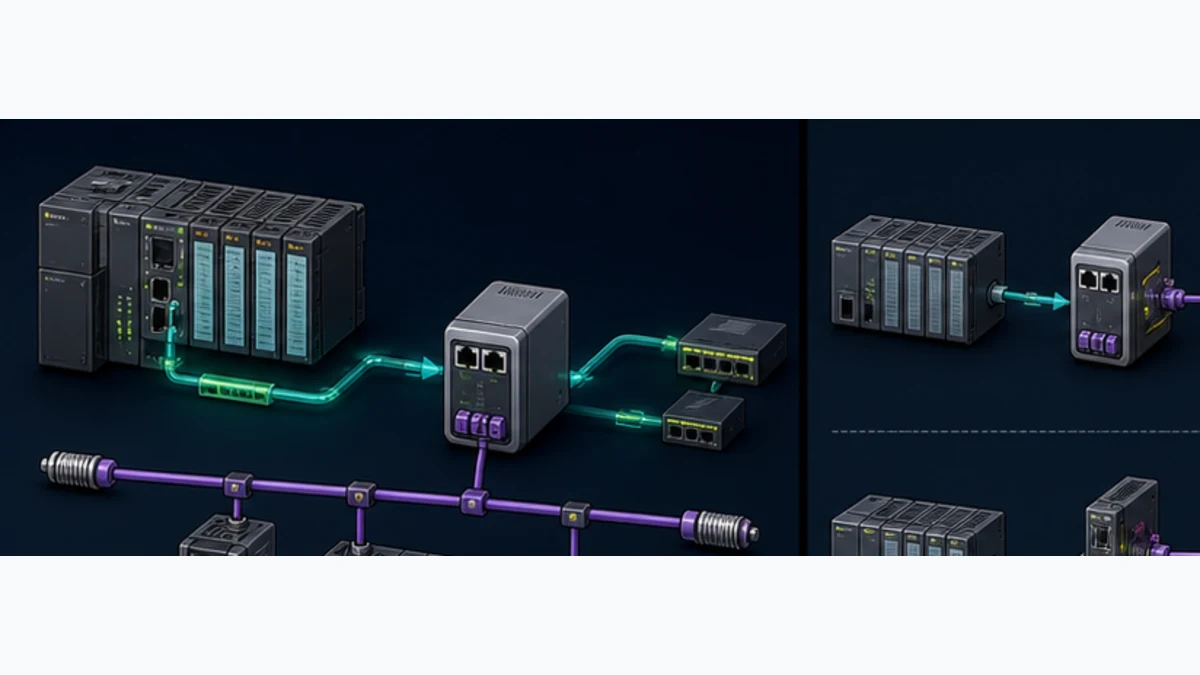
This guide owns the S7-1500-specific PN/CAN LINK integration. The S7-1200 CANopen CM module guide retains the established compact-controller side-module workflow. The CANopen PLC guide retains vendor-neutral physical-layer, NMT, PDO, SDO, EMCY and commissioning fundamentals.
Confirm the protocol and hardware architecture
PROFINET, CAN and CANopen are different interfaces
PROFINET is Industrial Ethernet. Classical CAN defines the data-link/physical bus and identifiers. CANopen adds a standardized object dictionary, communication objects, NMT state, error control and device profiles. PN/CAN LINK converts between a configured PROFINET device contract and one selected CAN-side operating mode. It is not a passive connector and it cannot infer an undocumented application protocol.
Before selecting it, obtain each field device manual and answer: Is the device CANopen CiA 301, another higher-layer CAN protocol such as J1939 or DeviceNet, or a proprietary raw CAN protocol? Does it require CANopen FD, LSS commissioning, a safety profile or synchronized motion behavior that the selected gateway does not implement? A product merely saying “CAN” is insufficient.
| Component | Required role | Configuration owner | Failure if confused |
|---|---|---|---|
| S7-1500 CPU | PROFINET IO Controller and application owner | TIA Portal hardware, PLC blocks and application DB | expecting native CAN identifiers from an Ethernet port |
| PN/CAN LINK | PROFINET IO Device plus CANopen Manager/Slave or transparent gateway | TIA Portal/HSP and selected operating mode | gateway is online on one side but wrong role on the other |
| CANopen field device | NMT device with exact object/PDO/profile behavior | manufacturer EDS/manual and gateway Manager project | similar node uses different PDOs or startup requirements |
| external CANopen manager | owns NMT/configuration when gateway is in Slave mode | external controller configuration | two managers contend or neither starts nodes |
| PLC interface block | maps gateway process/record data into typed application meaning | S7 program and versioned data contract | raw bytes appear plausible without quality or ownership |
Select the exact PN/CAN LINK product and lifecycle
Siemens Industry Mall identifies 6BK1620-0AA00-0AA0 as SIMATIC PN/CAN LINK for PROFINET to CAN/CANopen, supporting CAN 2.0A/B plus CANopen Manager and Slave roles described against CiA 301/302. Verify the installed label, hardware version, firmware, lifecycle/region, certifications, TIA release and HSP. Do not buy by enclosure photo or family name.
The current operating instructions list two switched PROFINET interfaces for line operation and a high-speed CAN interface. It documents Manager, Slave and transparent modes, CAN bit rates from 50 kbit/s to 1 Mbit/s and a possible physical length up to 1,000 m depending on rate, conductor and node count. Those are selection boundaries, not permission to design one maximum-size network without a cable/bit-timing calculation and representative test.
Choose CANopen Manager, Slave or transparent mode
Manager mode owns NMT and configured nodes
In CANopen Manager mode, PN/CAN LINK is the NMT Manager and configuration manager. Siemens documents support for up to 126 CANopen devices/slaves. During boot it can identify and configure nodes, write parameters by SDO according to the released project, control NMT state and exchange cyclic PDOs. The gateway can support heartbeat, node guarding, EMCY and SYNC functions described in its manual.
Do not design to the 126-node headline by default. CAN arbitration, PDO periods, payloads, heartbeat traffic, SYNC, SDO startup, cable length, transceiver load, S7 process image and required fault response can impose a much lower engineering limit. Calculate bus load and measure worst-case startup/cyclic behavior.
| CANopen state or event | What the Manager should prove | What the S7 application should do |
|---|---|---|
| Boot-up received | expected node identity has restarted and joined the monitored network | hold dependent commands until released startup completes |
| Pre-operational | node can exchange management traffic but ordinary PDO operation is not yet accepted | mark process values invalid and expose a precise state reason |
| Operational | released startup completed and cyclic communication is permitted | accept PDO data only with heartbeat, gateway and age checks |
| Stopped | NMT has deliberately stopped ordinary communication | drive outputs to the engineered fallback and retain first-out evidence |
| Heartbeat timeout | node state evidence is no longer current | reject the last PDO even if its bytes remain in the S7 image |
| EMCY received | device reported an emergency object with a specific code/register | capture raw evidence, apply the approved response and avoid blind reset loops |
Slave mode exposes S7 data to another manager
In CANopen Slave mode, an external NMT manager owns state and can configure the gateway's object dictionary/PDO relationship. The S7-1500 still exchanges its side of the contract over PROFINET. Siemens notes that the S7 user program provides a control bit that allows the gateway toward Operational, while the actual NMT transition is commanded by the current NMT manager. Document both permissions; an S7 bit cannot replace an absent external manager.
Define the exported EDS/object/PDO contract that the external manager consumes. Freeze gateway node ID, bit rate, object types, PDO COB-IDs/transmission types and application-validity behavior. Test the external manager's restart, replacement and mismatch response.
Transparent mode is raw CAN, not a fallback CANopen manager
Transparent CAN mode transfers configured raw CAN 2.0A/B frames across the gateway boundary. Your application owns identifiers, payload layout, schedules, timeout, duplicate/sequence handling, bus-off recovery and any higher-layer protocol. Do not use CANopen vocabulary for a transparent frame unless the application fully implements and validates that protocol—which is ordinarily a different product and conformance decision.
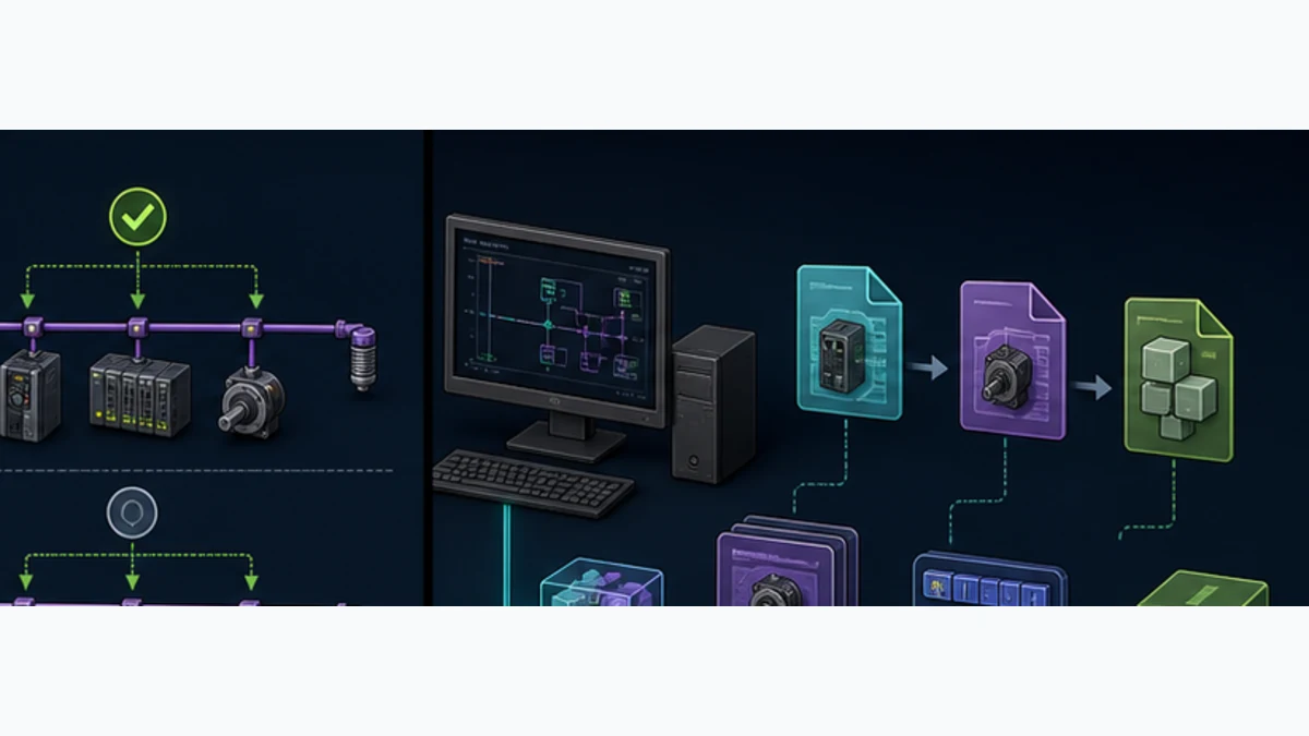
| Operating mode | Who owns CAN network state? | Primary data contract | Critical acceptance test |
|---|---|---|---|
| CANopen Manager | PN/CAN LINK | imported EDS devices, NMT/startup, PDO map and S7 image | wrong/missing node is diagnosed and application data becomes invalid |
| CANopen Slave | external CANopen manager | exported gateway EDS/OD/PDO map plus S7 image | external manager starts/stops gateway and both sides agree on direction |
| CAN transparent | S7/custom application | CAN identifier, length, byte contract, timing and recovery | injected frames, timeout, duplication, overload and bus-off are handled |
Design CAN wiring, bit timing and node identity
Build a linear bus with two physical-end terminators
High-speed CAN normally uses a linear trunk with short stubs and termination at the two physical ends. Use the exact PN/CAN LINK connector pinout and device manuals. Record CAN_H, CAN_L, reference/ground strategy, shield, connector, cable impedance, length, stub length and both terminating resistors. Do not assume every device includes switchable termination or that the gateway is located at a physical end.
With power controlled and all device-specific restrictions followed, a resistance measurement between CAN_H and CAN_L near approximately 60 ohms is a common indication of two 120-ohm end resistors in parallel. It is not a complete health test and other circuitry can affect the reading. Verify each terminator physically and use an analyzer/oscilloscope only with approved methods and competent personnel.
Select one bit rate and unique node IDs
All nodes on one CAN segment need compatible bit timing. Higher bit rate generally reduces permissible length and tightens physical constraints. The PN/CAN LINK manual's 50 kbit/s to 1 Mbit/s range and up-to-1,000-m statement are conditional. Use device-supported rates and the most restrictive cable/transceiver/manual limit.
Assign a unique CANopen node ID to every node including the gateway when applicable. The current PN/CAN LINK manual states that LSS functionality is not supported; do not plan to discover and dynamically assign anonymous devices through LSS. Preconfigure identities through each approved device method and keep a cabinet/network schedule.
| Physical design item | Released evidence | Failure if omitted |
|---|---|---|
| bus route | ordered trunk, endpoints and every stub | star wiring and long drops create reflections/intermittency |
| two terminators | exact endpoint locations and product values | missing/extra termination corrupts frames |
| bit rate | one value supported by gateway and every node | error frames and bus-off with no useful application traffic |
| node ID | unique ID, device identity and physical location | duplicate nodes produce ambiguous or unstable behavior |
| cable/connector | CAN-qualified product, pinout, length and environment | polarity, shield, contact or EMC fault is misdiagnosed as software |
| power/reference | voltage, current, protective device and reference strategy | nodes reset or transceivers exceed common-mode limits |
| capacity/bus load | PDO/heartbeat/SYNC/SDO schedule at worst case | network meets node-count ceiling but misses timing |
Freeze TIA Portal, HSP, EDS and firmware versions
Treat the compatibility set as one release artifact
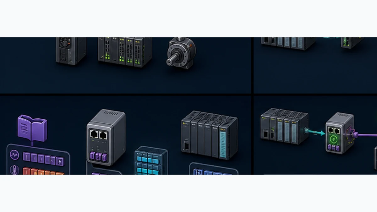
Archive the TIA Portal edition/update, S7-1500 CPU and firmware, PN/CAN LINK order number/hardware/firmware, HSP, EDS files, field-device firmware, PLC library/application-example version and gateway configuration. The current manual's capabilities may depend on PN/CAN LINK firmware such as V2.0 versus V2.1; do not apply one screenshot or parameter list to an unidentified unit.
An EDS describes a CANopen device's object/PDO capabilities for the manager configuration. Obtain it from the manufacturer, match the device/revision and retain the source/checksum. Siemens explicitly does not list XDD support for PN/CAN LINK in the cited feature boundary; an XDD file is not automatically an accepted substitute. The manual also excludes CANopen FD features, so Classical CAN/CANopen evidence cannot validate a CANopen FD device.
| Controlled item | Why it matters | Archive proof |
|---|---|---|
| TIA Portal and HSP | determines gateway catalog object, modes and parameter UI | installed versions and controlled installers |
| S7-1500 CPU/firmware | owns PROFINET controller and PLC block behavior | online identity and released hardware project |
| PN/CAN LINK hardware/firmware | selects feature set, diagnostics and manual revision | label/online identity and firmware package/source |
| EDS set | describes Manager-mode field devices and PDO/object options | manufacturer files, versions and checksums |
| gateway role/project | determines CANopen Manager, Slave or transparent ownership | TIA configuration export and compiled baseline |
| PLC blocks/types | implement cyclic interface, control and optional SDO services | library/application version and source review |
| acceptance baseline | proves identity, map, timing and failure response | raw captures, diagnostic export and signed results |
Live mini-lab
Try it: press START, then STOP
A stop-dominant seal-in rung: START latches the motor output through its own contact, and STOP breaks the circuit.
Watch the output lamp: it stays on after START until you press STOP.
Free to start · runs in your browserOpens plcsimulationsoftware.com — same team
Configure PN/CAN LINK in TIA Portal
Add the PROFINET device and select the CAN mode
Start from the backed-up project and online hardware inventory. Install the supported HSP if the exact gateway/firmware is absent from the catalog. Add PN/CAN LINK to the S7-1500 PROFINET network as an IO Device, assign the released device name/IP/network relationship, select its hardware version and set the intended CAN operating mode. Configure diagnostics and process modules/data sizes according to the exact manual.
PROFINET device name ownership matters independently of CANopen node ID. The S7-1500 may report a missing/wrong PROFINET device while every CAN conductor is healthy. Conversely, the gateway can be in PROFINET data exchange while CANopen nodes are Pre-operational or absent. Name alarms by boundary.
Configure Manager-mode devices from exact EDS files
In Manager mode, import each approved EDS, add the exact device, assign unique node ID and bit rate, select PDOs and configure NMT/startup/error-control behavior. Review any SDO startup writes; each can change device behavior. Minimize unnecessary PDOs because they consume bus/process capacity and increase configuration complexity.
Siemens documents that a Manager can perform SDO writes during boot as configuration manager. Decide whether the gateway or device nonvolatile memory is authoritative. A field-adjusted device should not silently become the new baseline. Retain the released values and test replacement with a deliberately different starting configuration.
Configure Slave mode as a versioned exported contract
In Slave mode, define only the required object/PDO data the external manager will use, export the EDS through the documented workflow and archive that exact file with both projects. The external manager and S7 application must agree on who produces each PDO and when data is valid. Test NMT Stop/Pre-operational/Operational transitions and gateway restart.
| Slave-mode authority | Owned decision | Acceptance evidence |
|---|---|---|
| external NMT manager | issues the actual CANopen state transitions and supervises the gateway node | trace shows the intended Pre-operational, Operational, Stop and restart sequence |
| S7 user program | sets the documented permission/control bit and owns local application readiness | permission changes are visible and cannot be confused with the external NMT command |
| PN/CAN LINK configuration | fixes node ID, bit rate, exposed objects and PDO contract | exported EDS and compiled TIA project match the installed gateway |
| producer of each value | updates the assigned TPDO/RPDO source with explicit validity semantics | multiple asymmetric test values move in the documented direction |
| receiving application | rejects stale, invalid or wrong-state data and applies fallback | controlled manager, PROFINET and CAN interruptions produce distinct alarms |
Map PDOs through the gateway into S7 data
Name directions from the CANopen device viewpoint
A TPDO is transmitted by the CANopen node that owns it; an RPDO is received by that node. Therefore, a drive's TPDO can flow through PN/CAN LINK into S7 input data, while S7 command output can become the drive's RPDO. When PN/CAN LINK is in Slave mode, “gateway TPDO” points outward to the external manager. Always write both endpoints and the application direction.
Map each object index/subindex and CANopen type to a PDO byte/bit offset, then to the PN/CAN LINK PROFINET input/output item and a typed S7 structure. Include status, NMT/heartbeat health, data age and application validity. Do not scatter gateway %I/%Q addresses through control blocks.

| Map field | Example description | Proof |
|---|---|---|
| node and role | node 7 drive under gateway Manager | online identity, NMT and boot evidence |
| CANopen object | exact index/subindex, access and data type | EDS plus device object manual |
| PDO | node TPDO/RPDO, COB-ID, transmission type and bit position | gateway Manager configuration/export |
| gateway image | PROFINET module/item, byte.bit offset and direction | compiled TIA hardware and online raw bytes |
| S7 type | signed/unsigned width, structure and alignment | typed DB/interface review |
| conversion | byte order, scale, offset, unit and limit | asymmetric raw patterns and reference measurement |
| validity | PROFINET quality, gateway state, node state/heartbeat and application age | controlled failure tests invalidate the value |
| command ownership | one state machine/HMI/sequence authority | arbitration test and safe fallback |
Test byte order and sign with asymmetric patterns
Use values that expose reversal and sign faults, such as 16#1234, 16#0081, negative signed values and non-round scaled points. Capture the CAN payload when safely possible, gateway raw image, S7 raw field and normalized engineering value. Repeat for 32-bit and floating values using the exact object type; do not generalize one byte-swap rule to all structures.
Read and write SDOs through controlled PLC services
Use PDO for cyclic control and SDO for explicit access
PDOs carry routine cyclic process data with configured timing. SDOs address object dictionary entries for configuration, identification and diagnostics. Siemens' application example for PN/CAN LINK demonstrates S7-1500 access using LCan_SdoRead and LCan_SdoWrite patterns that operate through acyclic PROFINET records such as RDREC and WRREC, with detailed status fields. Use the current supported example/library for the exact environment rather than recreating a state machine from screenshots.
An SDO request is asynchronous. Trigger once, wait while busy, handle completion/error, preserve the hexadecimal status/subfunction status and validate returned length/type. Do not start one request every scan. Serialize access as required, apply timeouts derived from documented behavior and prevent competing HMI/PLC/service operations.
| SDO operation | Preconditions | Completion proof |
|---|---|---|
| identity read | correct gateway role, node, index/subindex and buffer | done without error; returned type/value matches device manual |
| diagnostic read | device supports object and state permits access | raw abort/status retained and interpreted from exact sources |
| bounded parameter write | approved machine state, user authority, range/type and baseline | done, readback matches and functional test passes |
| recipe sequence | exact device identity and ordered released entries | every write logged; final comparison and process test pass |
| replacement restore | approved spare plus authoritative parameter set | identity first, writes complete, PDO/map and function revalidated |
Treat parameter writes as OT changes
A CANopen parameter can change current limit, direction, filter, control mode, scaling or safety-adjacent behavior. Expose only reviewed parameters through bounded application services. Record user, device identity, old/new value, unit, timestamp, block status and readback. Do not offer arbitrary node/index/subindex entry from an ordinary operator HMI.
Commission the two-network system in gates
Prove PROFINET before CANopen and meaning after both
Commission with machine energy in the approved safe state. Capture the existing S7 project, gateway configuration and device parameters before downloads. Validate the gateway's PROFINET relationship first, then CAN physical/network state, then PDO/SDO data, then application behavior. This order prevents replacing CAN devices for a PROFINET naming fault.
- Archive TIA/HSP, CPU/gateway/device identities, firmware, EDS files, mappings and parameter baselines.
- Verify 24 V supplies, protective devices, CAN topology, polarity, shield/reference, two end terminators and unique node IDs.
- Add/identify PN/CAN LINK on the correct S7-1500 PROFINET network and verify released device name/IP.
- Select one CAN operating mode and compare every parameter with the design.
- In Manager mode, import exact EDS devices and release NMT, PDO, heartbeat and startup/SDO policy.
- Compile the complete project and review hardware/process-image changes before activation.
- Download with commands inhibited; prove S7 RUN, PN/CAN LINK PROFINET IO data exchange and exact gateway diagnostics.
- Prove CAN bit rate, gateway role/state and every required CANopen node identity/NMT/heartbeat.
- Stimulate known raw PDO patterns and validate mapping, byte order, type, scale, status and age.
- Read one harmless identity object and perform only approved bounded SDO writes with readback.
- Create controlled PROFINET loss, CAN cable/node loss, heartbeat timeout, wrong-node and recovery tests.
- Enable field commands progressively and complete machine, motion and independent safety acceptance.
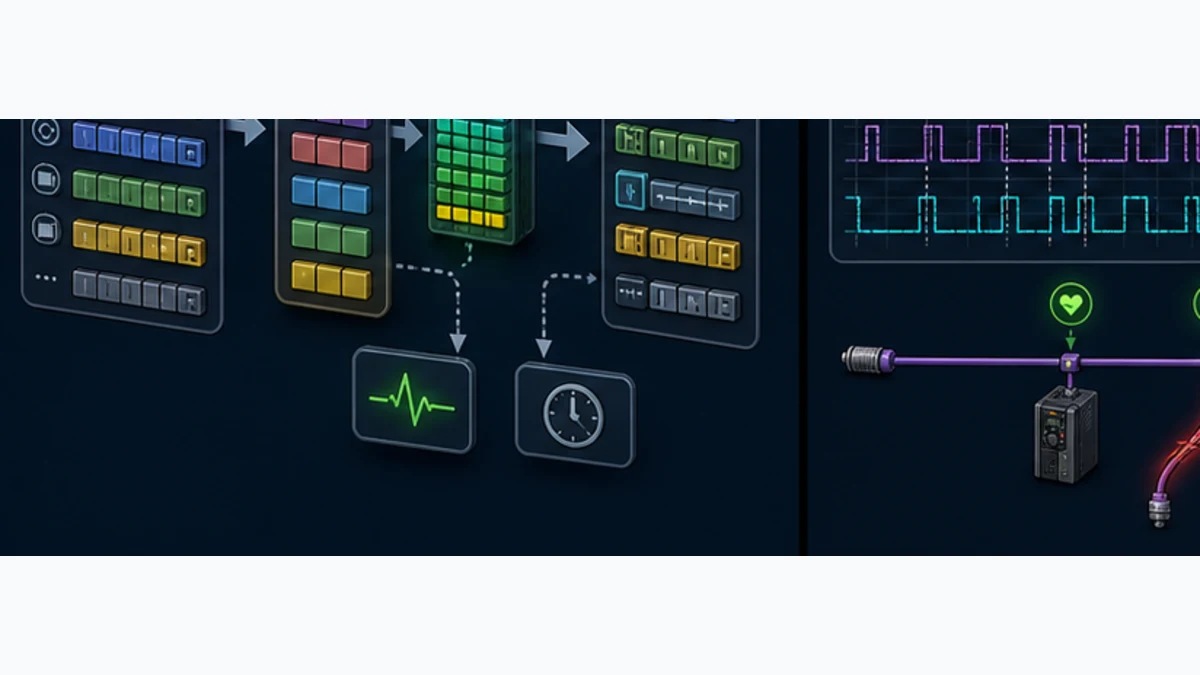
| Test | Stimulus | Evidence | Reject if |
|---|---|---|---|
| PROFINET identity | power approved gateway with released project | correct device name, product/module and IO status | generic reachability is counted as IO exchange |
| CAN boot | start gateway with released node set | bit rate, node identities, boot/NMT/heartbeat and no unexpected EMCY | missing node is silently ignored |
| PDO map | apply multiple known device values/commands | frame or device evidence, gateway bytes, S7 types and process response | only zeros/full scale were tested |
| SDO | read identity then write one bounded lab parameter | request status, result, readback and functional outcome | requested HMI value is mistaken for confirmed device value |
| PROFINET break | safely interrupt controller-gateway path | TIA diagnostics, data quality, stale rejection and fallback | CAN status hides invalid S7 image |
| CAN break | safely interrupt selected CAN segment/node | gateway CAN diagnostic, NMT/heartbeat, affected PDO and application response | PROFINET stays green and PLC accepts old PDO |
| wrong node | substitute controlled incompatible identity | Manager startup/configuration rejection and clear alarm | product mismatch produces plausible application data |
| restart/replacement | power cycle and install approved spare | automatic/manual recovery follows released authority and acceptance | online intervention is required but undocumented |
Diagnose S7-1500 CANopen in boundary order
Layer 1: S7-1500 to PN/CAN LINK over PROFINET
Start with CPU diagnostics, expected/actual PROFINET device identity, module/submodule configuration, device name/IP, port/link/topology, IO data quality and gateway supply. A BF/SF indication is a symptom whose exact pattern comes from the current manual. Preserve the diagnostic buffer and device diagnostics before resetting.
If the PROFINET IO Device is absent or wrong, CANopen analysis is premature. Resolve the controller-device contract, then confirm input/output data quality and update behavior. An engineering ping or web response does not prove cyclic PROFINET IO.
Layer 2: PN/CAN LINK mode and CANopen network
Confirm selected Manager/Slave/transparent mode, gateway CAN state, bit rate, node ID and network authority. In Manager mode, inspect missing/wrong nodes, NMT state, boot configuration, heartbeat/node guarding, EMCY and SDO abort/status. In Slave mode, inspect whether the external NMT manager commands Operational and whether the S7 control/permission bit allows it.
CAN controller error counters, error-passive/bus-off state and analyzer captures help distinguish wiring/bit-rate overload from application mapping. Use competent safe measurement. Do not change bit rate or termination randomly until communication appears; preserve the first fault and compare with the released schedule.
Layer 3: PDO/SDO mapping and application validity
When both networks communicate but the value is wrong, compare EDS/device object definition, selected PDO, direction, gateway offset, PROFINET item, S7 type, byte order, sign, scale and quality. A heartbeat proves node liveness, not measurement validity. An Operational node can still report channel faults or stale physical data.
| Symptom | First discriminating evidence | Likely boundary | Next controlled action |
|---|---|---|---|
| gateway missing in TIA online view | configured/actual PROFINET name and product/module identity | PROFINET configuration | assign/restore released identity and compare hardware catalog/HSP |
| gateway online but no CAN nodes | operating mode, CAN bit rate, controller state and first physical segment | gateway/CAN physical | verify exact mode, power, polarity, termination and rate |
| one node missing | node ID, identity, heartbeat and analyzer/error evidence | device/drop/duplicate ID | inspect that node power/drop; compare ID and known-good device |
| all nodes unstable | CAN error counters, rate, two terminations and trunk topology | physical/bus load | restore released wiring/rate; isolate segments under approved method |
| node Pre-operational | NMT manager, startup SDO result and device EMCY/abort | configuration/device | preserve exact abort/status; compare EDS and parameter permissions |
| gateway Slave never Operational | external NMT state plus S7 control bit | dual authority | prove both permission and external NMT command sequence |
| PDO bytes stay zero | node NMT, PDO transmission type/mapping and gateway/S7 offsets | mapping/state | stimulate asymmetric value; trace device PDO through gateway image |
| value updates but is wrong | raw bytes, type, byte order, scale and device channel status | data contract | compare exact object and apply multiple reference patterns |
| SDO block stays busy/errors | request edge/state, node/index, buffer, RDREC/WRREC and detailed status | PLC/gateway/service | stop retriggering; retain hexadecimal status and use exact example/manual |
| intermittent dropout under load | CAN bus load/error counters, heartbeat timing and S7/PN update history | capacity/timing/physical | time-correlate traffic, power and environment before increasing timeout |
| drive communicates but motion fails | CiA 402 state/mode, control/status words, timing and drive fault | application/motion | validate exact drive profile and choose supported motion architecture |
Control drives without overclaiming motion capability
CiA 402 mapping is not a Siemens technology object
A CANopen drive may implement CiA 402 controlword, statusword and operating modes. Mapping those objects through PN/CAN LINK can support an engineered application, but it does not automatically create a PROFIdrive telegram, S7-1500 technology object, isochronous PROFINET axis or safety-integrated motion solution. Determine required speed/torque/position control, update and synchronization before selecting the gateway.
For ordinary commands, implement the drive state machine explicitly, validate status/fault feedback, supervise communication and prevent stale controlword use. For coordinated motion, electronic gearing, high-performance position loops or safety motion, use a controller/drive/interface architecture explicitly supported for those requirements unless the complete CANopen design is proven.
Govern replacement, cybersecurity and functional safety
Replacement crosses three configuration owners
A replacement can be the S7 project/gateway, gateway CANopen configuration or field-device parameters. Identify which source is authoritative. In Manager mode, startup SDO writes may restore device settings; in Slave mode, the external manager may own them. A service laptop edit must not silently supersede both.
After replacement, prove product/revision, gateway role, PROFINET identity, node identity, parameter baseline, PDO map, raw/scaled values, diagnostics, fallback and actual machine function. Communication returning is only an intermediate gate.
Secure engineering and parameter surfaces
Restrict TIA Portal project/download rights, engineering stations, remote access, PROFINET management and SDO/HMI parameter functions. Apply current Siemens product-security guidance and advisories, network segmentation, named access, backups and change records. The raw CAN side has no inherent authorization for a received frame; protect physical access and the upstream gateway/application path.
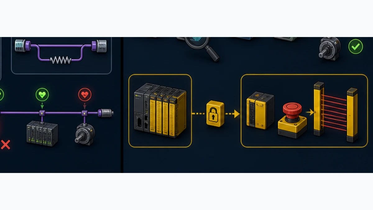
Ordinary PN/CAN LINK data is not a safety channel
Standard PROFINET-to-CANopen PDOs, heartbeat, EMCY and PLC watchdogs are not by themselves functional-safety communication. A fail-safe S7-1500 CPU does not make an ordinary PN/CAN LINK and standard CANopen drive data safe. Use certified PROFIsafe, CANopen Safety or another approved architecture with the required components, calculations and lifecycle where a function is credited to PL/SIL.
Do not use a browser simulator, heartbeat bit or software timeout as the sole emergency-stop, guard or safe-motion function. Test communication faults and safety response independently under the risk assessment.
Frequently asked questions
Does the Siemens S7-1500 have CANopen built in?
Do not assume so. The integrated S7-1500 communication architecture commonly provides PROFINET, not a CAN_H/CAN_L CANopen port. A documented route uses SIMATIC PN/CAN LINK as a PROFINET IO Device gateway to CAN/CANopen. Verify the exact CPU and project because other supported communication products may exist for specific applications.
Which CANopen gateway works with an S7-1500?
Siemens documents SIMATIC PN/CAN LINK, article 6BK1620-0AA00-0AA0, for PROFINET to CAN/CANopen. It supports documented CANopen Manager, CANopen Slave and CAN transparent modes. Confirm lifecycle, firmware, TIA/HSP, protocol/profile, capacity, environment and safety requirements before purchasing.
How do I add PN/CAN LINK in TIA Portal?
Install the supported HSP if necessary, add the exact PN/CAN LINK hardware to the S7-1500 PROFINET network, assign the released device name/network parameters, select CANopen Manager, Slave or transparent mode, configure process modules and diagnostics, then build the exact CAN-side configuration. Compile and activate only under controlled machine energy.
Can PN/CAN LINK be a CANopen Manager and Slave?
It supports both operating modes, but one project selects the intended role. In Manager mode it owns NMT and configured device startup. In Slave mode an external CANopen manager owns NMT and the gateway exposes a versioned object/PDO contract backed by S7 data. Do not configure two competing managers.
How many CANopen nodes can PN/CAN LINK manage?
The current Siemens operating instructions state up to 126 CANopen devices/slaves in Manager mode. Treat that as a product ceiling, not a practical design target. PDO rate, SYNC, heartbeat, SDO startup, bus load, physical length, process image, diagnostics and recovery requirements can impose a lower limit.
Does PN/CAN LINK support CANopen FD or LSS?
The cited current manual explicitly does not support the listed CANopen FD standards or LSS functionality. It supports Classical CAN 2.0A/B and documented CANopen features. Preconfigure node IDs through approved device methods and choose another verified product if CANopen FD or LSS is mandatory.
How do I map CANopen PDOs into S7-1500 tags?
Document each device object and TPDO/RPDO bit layout, map it through the PN/CAN LINK CANopen configuration to the gateway's PROFINET process item, then link that item to a dedicated typed S7 DB/UDT. Prove byte order, sign, scale, status and freshness with asymmetric field patterns.
How can the S7-1500 read and write a CANopen SDO?
Use the current Siemens-supported PN/CAN LINK application pattern/library, such as the documented LCan_SdoRead and LCan_SdoWrite workflow through acyclic PROFINET records. Trigger once, respect busy/done/error, retain detailed hexadecimal status, validate returned type/length and read back bounded writes.
Why is PN/CAN LINK online but CANopen data is zero?
PROFINET IO exchange proves only the S7-to-gateway side. Check gateway operating mode, CAN bit rate and wiring, node identity, NMT Operational state, heartbeat, EDS/PDO assignment, transmission type, gateway offset, S7 mapping and application validity. Trace one known nonzero asymmetric value through every layer.
Can S7-PLCSIM prove a real PN/CAN LINK network works?
Simulation can test PLC mapping functions, SDO state-machine wrappers and application fallback with modeled inputs. It cannot prove the physical gateway, PROFINET identity, CAN wiring/termination, bit timing, node firmware, PDO traffic, bus load, EMCY behavior or field response. Complete representative hardware acceptance separately.
Practical next step
Photograph the S7-1500, candidate gateway and every CAN device label. Write one architecture line—S7-1500 PROFINET Controller → exact PN/CAN LINK in Manager/Slave/transparent mode → named CAN nodes—then build a map for one device from object/PDO to gateway offset to S7 type and validity. If the role, identity or map cannot be written unambiguously, do not activate the gateway yet.
Sources, review scope and limitations
This guide was reviewed on August 30, 2026. Product capabilities, firmware, HSPs, TIA releases and lifecycle can change. Manager/slave names are retained where they are exact product/API terminology. Only current manuals for the installed products, the approved project, risk assessment and witnessed acceptance authorize a machine change.
- Siemens, SIMATIC PN/CAN LINK operating instructions, current February 2024 edition.
- Siemens Industry Mall, PN/CAN LINK article 6BK1620-0AA00-0AA0 product record.
- Siemens, PN/CAN LINK Manager and Slave configuration application example.
- Siemens, PN/CAN LINK SDO communication with S7-1500,
LCan_SdoReadandLCan_SdoWrite. - Siemens Industry Online Support, PN/CAN LINK application-example entry 109751077.
- Siemens, SIMATIC S7-1500 and ET 200MP system manual.
- Siemens, S7-1500 communication function manual.
- Siemens, PROFINET with STEP 7 function manual.
- Siemens, Guide to Industrial Security.
- Siemens ProductCERT, security advisories and notifications.
- CAN in Automation, CANopen overview and communication profiles.
- CAN in Automation, CANopen network management.
- CAN in Automation, CANopen error-control protocols and heartbeat.
- CAN in Automation, CANopen PDO protocol.
- CAN in Automation, CANopen SDO protocol.
- CAN in Automation, CANopen lower layers and physical design.
- PROFIBUS & PROFINET International, PROFINET technology and system description.
- OSHA, Control of hazardous energy, 29 CFR 1910.147.
The six figures are original conceptual editorial illustrations. They are not Siemens/CiA product drawings, connector pinouts, software screenshots, approved topologies, timing guarantees, status-code references or safety designs. SIMATIC, S7-1500, TIA Portal and PN/CAN LINK are Siemens product names. CANopen is a CAN in Automation technology. This independent educational page is not an official manufacturer publication.
Now run it · free to start
Follow plant data from sensor to SCADA
Fieldbus versus Ethernet, Modbus, EtherNet/IP, PROFINET, OPC UA and MQTT, then SCADA layers and alarms, taught on simulated equipment. Free to start.
Ownership disclosure: PLC Programming IO and PLC Simulation Software are operated by the same publisher.
PLC Programming IO Editorial Team
Industrial automation education, references, and software testing
The PLC Programming IO Editorial Team publishes sourced industrial-automation education and documents how material is reviewed, tested, and corrected. A team byline means the publisher is responsible for the page; it does not represent a fictional person or imply an engineering licence.
Coverage:
- • PLC programming concepts and examples
- • Vendor software tutorials and comparisons
- • SCADA, HMI, protocols, and instrumentation
- • Training, careers, and reference material
Review standard:
- • Prefer primary and official sources
- • Record software versions when material
- • Separate tested facts from estimates
- • Publish material corrections
Important scope note
This site provides education, not project-specific engineering approval. Safety, code, and compliance decisions require a qualified person with access to the actual machine and jurisdiction.