CANopen PLC Guide: Architecture, Configuration and Troubleshooting
Integrate CANopen with a PLC using the object dictionary, EDS/DCF files, PDO and SDO services, NMT states, heartbeat supervision and evidence-led commissioning.
Review status: Editorially reviewed against cited CAN in Automation specifications and knowledge resources plus Siemens, Schneider Electric and Beckhoff implementation documentation; exact compatibility, bit timing, topology, object support, startup behavior and safe machine response require verification for the installed products and network
Direct answer
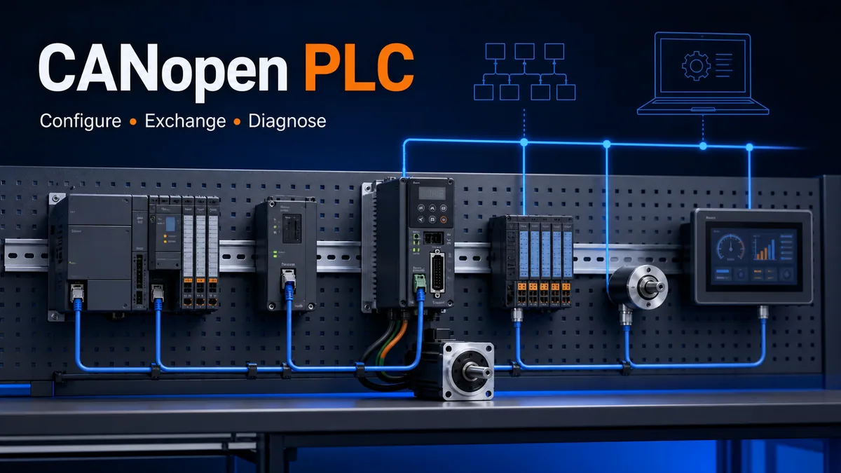
A CANopen PLC communicates with drives, I/O, sensors, encoders and other embedded controllers through a CANopen manager or device function implemented in the PLC, a communication module or a gateway. CANopen adds a standardized device model and communication services above the CAN lower layers. The PLC normally exchanges time-sensitive process values through PDOs, reads or writes configuration and diagnostic objects through confirmed SDO transfers, manages device state through NMT, supervises presence with heartbeat/error-control services, and consumes EMCY diagnostic messages where supported.
A reliable project aligns six contracts: compatible CANopen generation and device profiles; one physical bus design; unique node identities and common bit timing; the correct EDS/DCF and object-dictionary revision; explicit PDO direction, mapping, trigger and PLC data types; and deterministic startup, supervision, fault and recovery behavior. A green PLC tag proves only the final mapping layer. It does not prove wiring, valid CAN frames, correct NMT state, fresh process data or a healthy actuator.
Commission from the bottom upward. Verify product support and controlled source files, inspect the unpowered topology against every device manual, establish the CAN link and error-counter baseline, observe boot-up/NMT/heartbeat, prove SDO access, validate each PDO byte/bit mapping against an object reference, then enable application commands under the machine’s approved safety and commissioning procedure. Troubleshoot in the same layer order and preserve the first diagnostic evidence before resetting anything.
Understand what CANopen adds to CAN
Separate the lower layers from the application layer
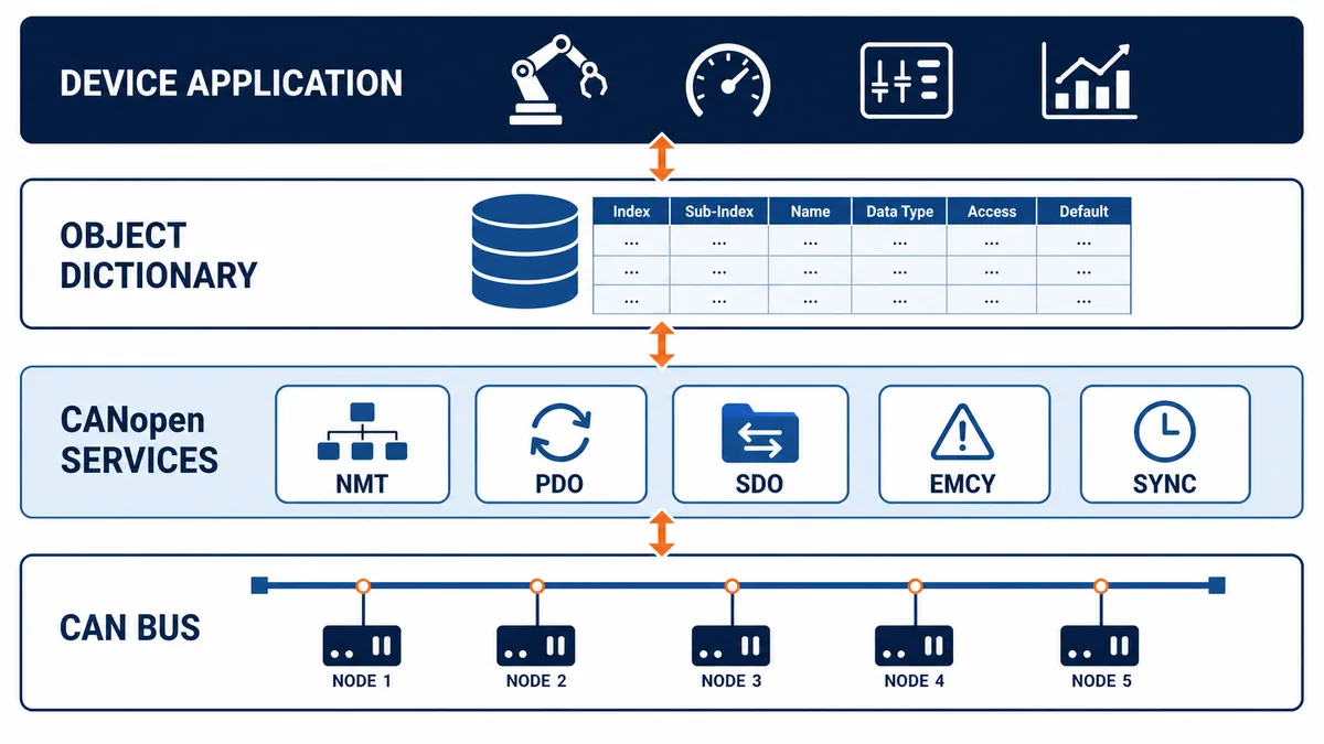
CAN supplies the frame transport, arbitration and error-handling mechanisms at the lower layers. CANopen defines how devices organize data and use CAN frames for device configuration, process exchange, network state, synchronization and diagnostics. Two products can both contain CAN transceivers yet remain unable to communicate because one uses raw proprietary CAN frames, J1939, DeviceNet or another higher-layer protocol instead of the required CANopen profile.
CAN in Automation identifies classic CANopen—now often called CANopen CC—as the CiA 301 application layer and communication profile based on Classical CAN. CANopen FD is specified in CiA 1301 and uses CAN FD. They are related architectures, not names to interchange in a bill of materials. Confirm which generation every manager, device, interface, cable segment and engineering tool supports.
| Layer or artifact | Responsibility | Evidence to inspect |
|---|---|---|
| physical medium | differential signaling, cable, connectors, reference, topology and termination | approved drawings, device manuals and physical inspection |
| CAN data link | identifiers, arbitration, frames, acknowledgement and error handling | CAN analyzer frames and controller/transceiver counters |
| CANopen communication | NMT, PDO, SDO, EMCY, SYNC and error control | object dictionary, trace and stack status |
| device profile | standardized semantics for a class of device | implemented profile and conformance claims |
| device application | actual I/O, drive, sensor or controller behavior | manufacturer object manual and state model |
| PLC application | commands, status, sequences, interlocks and diagnostics | typed mappings, code review, trends and tests |
Use device profiles without assuming identical products
CANopen profiles define common object and diagnostic semantics for device classes. CiA highlights CiA 401 for generic I/O and CiA 402 for drives and motion control among widely used profiles. A profile improves interoperability, but optional objects, supported modes, PDO defaults, limits and manufacturer-specific ranges still differ. Confirm the exact profile version and every object your application depends on.
Choose the PLC architecture and role
Manager, device and transparent modes are different designs
The PLC may host the CANopen stack directly, exchange process data with a dedicated CANopen module, or communicate through a gateway. In a manager role, the platform may perform NMT management, device configuration with SDO writes and boot-up supervision. Siemens documents an ET 200SP CM CAN mode that can act as a CANopen manager, a CANopen slave/device or in transparent CAN mode; those modes expose materially different interfaces and responsibilities.
Do not call every PLC the “master” without defining functions. Modern CiA language distinguishes NMT manager and NMT server/device roles. A PLC can be an NMT manager yet still only consume certain PDOs, or it can expose its own object dictionary as a device while another controller manages the network.
| Architecture | PLC sees | Engineering advantage | Risk to control |
|---|---|---|---|
| native controller interface | CANopen devices and objects in the controller project | close integration with variables, tasks and diagnostics | controller/firmware-specific capability and limits |
| local communication module | cyclic I/O/status plus module services | isolates bus handling and can simplify CPU integration | two configurations: module network and PLC interface |
| remote gateway | another industrial protocol on PLC side, CANopen on field side | reuse where PLC lacks CANopen hardware | added conversion, timing, diagnostics and failure boundary |
| transparent/raw CAN | raw frames or buffers | maximum protocol flexibility | application must implement/validate higher-layer behavior |
| PLC as CANopen device | mapped PLC data exposed to an external manager | fits coordinated embedded or machine networks | manager owns startup and expected device behavior |
For the established SIMATIC compact-controller path, use the dedicated S7-1200 CANopen CM module guide. It covers the 021620-B/021730-B product boundary, TIA Portal plus CM CANopen Configuration Studio workflow, process-image transfer, byte-order proof and the unconfirmed S7-1200 G2 compatibility boundary. For the modular controller family, the S7-1500 CANopen PN/CAN LINK setup and diagnostics guide owns the two-network gateway architecture, Manager/Slave authority, EDS/PDO mapping and SDO service path.
Verify capacity and timing before selecting hardware
Record supported node count, PDO count and byte capacity, SDO client/server channels, NMT services, heartbeat consumers/producers, SYNC behavior, EMCY handling, device profiles, task/interface update, diagnostic access and supported EDS/DCF revisions. A module advertised as “CANopen capable” may not support the manager function, dynamic mapping or device profile required by the design.
Engineer the physical bus before importing devices
Use one documented line topology
CiA’s CANopen lower-layer guidance assumes an ISO 11898-2 physical layer for ordinary interoperable CANopen applications and publishes bit-timing/topology guidance. Build the bus as the manufacturer and project documents require, normally a line/trunk with termination at both physical ends and short stubs. Long branches, star wiring, extra termination, unsuitable connectors or an undocumented reference/shield arrangement can produce intermittent errors that look like software faults.
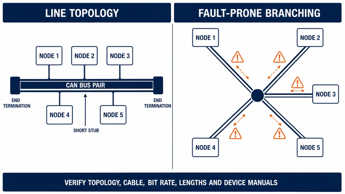
Never disconnect, resistance-test or reterminate an energized or operational machine network without authorization and the required hazardous-energy/electrical procedure. Parallel equipment and transceiver electronics can distort simple resistance readings. Use an approved test plan and the correct CAN analyzer or oscilloscope methods for energized signal evidence.
Treat bit rate, trunk length and stubs as one constraint
Every active node must use compatible bit timing. CiA publishes indicative CANopen CC combinations such as 1 Mbit/s over 25 m, 500 kbit/s over 100 m, 250 kbit/s over 250 m and 125 kbit/s over 500 m, with associated stub restrictions. These are standards guidance, not permission to use the maximum on every installation. Cable characteristics, transceivers, connectors, stubs, environment and manufacturer limits can require a more conservative design.
| Physical check | Correct evidence | Misleading shortcut |
|---|---|---|
| actual trunk route | as-built endpoint-to-endpoint walkdown | counting nodes in engineering software |
| end termination | exactly as required at physical ends | enabling every device’s termination switch |
| stub lengths | measured and compared with project/bit-rate limit | assuming a junction box is electrically transparent |
| cable/connector | specified impedance/construction and pin assignment | using any convenient twisted pair |
| bit timing | verified setting at every active interface | accepting a matching nominal number alone |
| reference/shield | installed per all device and EMC documents | improvising a ground connection during fault finding |
| signal health | analyzer/error counters, and waveform only by qualified method | judging network health from an HMI online icon |
Make the object dictionary the source of data meaning
Address every object by index and sub-index
The CANopen object dictionary organizes communication parameters and application data. CiA describes each entry with a 16-bit index and 8-bit sub-index. The 1000h–1FFFh range holds communication-profile objects; 2000h–5FFFh is manufacturer-specific; 6000h–9FFFh is associated with standardized profiles. Access rights, data type, size, default and persistence are part of the object contract, not implementation trivia.
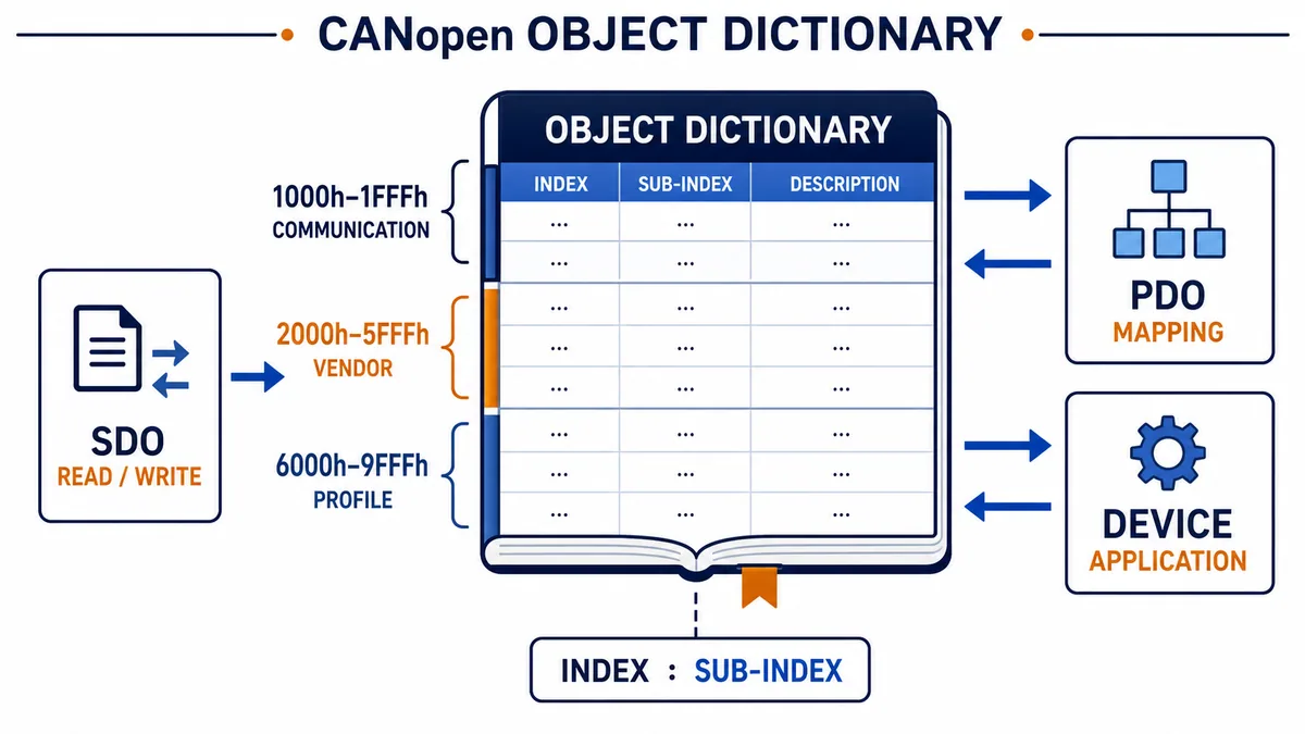
Build a controlled interface list rather than scattering hexadecimal constants through code. For each consumed or produced object, record the device/project revision, index/sub-index, name, type and signedness, length, byte/bit position, units, scale, access, update trigger, timeout, valid state and PLC destination tag.
Distinguish EDS description from configured DCF
CiA 306 defines electronic device description formats. An EDS describes the functions and properties of an unconfigured CANopen device. A DCF adds configuration properties for a specific network/device instance. Import files from the device manufacturer and retain their checksum/version with the project. A filename copied from another machine is not proof that its product revision or optional modules match.
| Artifact | Contains | Control required |
|---|---|---|
| manufacturer object manual | semantic meaning, modes, units, limits and behavior | exact product/firmware revision |
| EDS | available objects and device capabilities in standardized text format | original source, version and checksum |
| DCF | device description plus instance-specific configuration | node identity, bit rate and approved parameter values |
| manager project | imported device, PDO mapping, startup writes and supervision | controlled software and module firmware |
| PLC tag map | typed application destinations and sources | code revision and interface owner |
| as-left evidence | values actually read/written and tested | timestamp, device identity and approver |
Live mini-lab
Try it: press START, then STOP
A stop-dominant seal-in rung: START latches the motor output through its own contact, and STOP breaks the circuit.
Watch the output lamp: it stays on after START until you press STOP.
Free to start · runs in your browserOpens plcsimulationsoftware.com — same team
Map PDO and SDO services to the right jobs
Use PDOs for compact time-sensitive process exchange
CiA describes CANopen CC PDOs as high-priority control/status data carried in a single Classical CAN frame with up to eight bytes of application data. An RPDO is received by the device; a TPDO is transmitted by the device. Those directions are from the CANopen device’s viewpoint, so a drive’s TPDO commonly becomes PLC input/status data and its RPDO commonly carries PLC output/command data.
PDO communication parameters define the CAN identifier and transmission trigger; mapping parameters define which object values occupy which positions. Triggers can be synchronous, event-driven or timer-driven depending on supported configuration. The PLC task and interface update must consume data with a defined age and apply outputs with a defined deadline.
Use SDOs for confirmed object access
SDOs provide confirmed client-server access to an object dictionary. CiA documents expedited, segmented and block transfer variants; expedited transfer carries small values directly, while other variants handle more data. SDO is useful for startup configuration, identification and on-demand diagnostics. It is generally not a substitute for continuously mapped time-sensitive process data.
| Service | Primary purpose | Delivery character | PLC implementation question |
|---|---|---|---|
| PDO | compact control/status process data | unconfirmed broadcast, trigger configured | direction, mapping, trigger, freshness and safe stale response |
| SDO | configuration and diagnostic object access | confirmed client-server transfer | request state, timeout, abort code, type and retry policy |
| NMT | control/observe communication state | network management command/state | who owns transitions and recovery? |
| heartbeat/error control | supervise node presence/state | cyclic/event supervision | producer time, consumer timeout and consequence |
| EMCY | report device error condition | diagnostic event | code/register capture, acknowledgement and application response |
| SYNC | coordinate synchronous PDO behavior | network synchronization object | producer ownership, period, window and task alignment |
Do not repeatedly poll dozens of objects by SDO because PDO mapping was inconvenient. It can add unpredictable load and obscure freshness. Conversely, do not burn cyclic PDO bandwidth on a parameter needed once during maintenance. Match service semantics to data use.
Control NMT startup, supervision and recovery
Make state transitions visible to the PLC
The CANopen NMT state machine includes initialization, pre-operational, operational and stopped states. Pre-operational allows configuration/diagnostic communication while ordinary PDO exchange is not active. Operational enables the configured PDO behavior. Stopped restricts communication according to the CANopen state rules. Boot-up and transition details depend on the manager configuration and device implementation.
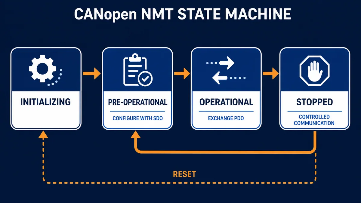
Record expected startup order: identify booted nodes, validate identity, perform supported configuration downloads, confirm responses, start only approved devices, validate operational state and then release machine commands through application permissives. A manager setting such as “auto-start all” is a consequential behavior, not a convenience checkbox.
Supervise presence without treating it as process proof
Heartbeat monitoring lets consumers detect a missing producer or observe its NMT state. Schneider’s manager documentation distinguishes heartbeat from node guarding and exposes producer/consumer timing. Beckhoff documents use of heartbeat objects and node error response in its CANopen integration. Configure times from network/application requirements and account for startup, maintenance and transient load.
A heartbeat proves that a protocol stack is alive enough to publish state. It does not prove that PDO data is fresh, mapped correctly, accepted by the device application or producing physical motion. Separately monitor process-data age, device status word and real equipment feedback.
| Condition | What it proves | What it does not prove |
|---|---|---|
| CAN frames present | at least one interface is transmitting detectable traffic | correct bit timing at every node or valid CANopen semantics |
| boot-up observed | a node reset/initialized and announced availability | configuration succeeded |
| heartbeat current | producer is reporting a state within the timeout | PDO freshness or actuator health |
| SDO upload succeeds | object access and request/response path work | PDO mapping or operational state |
| NMT operational | stack is in the operational communication state | application is enabled or safe to command |
| PDO changing | mapped bytes are arriving/transmitting | correct type, scale, sign or physical result |
| EMCY absent | no current reported emergency event was observed | device and process are fault-free |
Bind CANopen data safely into the PLC application
Convert bytes into typed, qualified signals
Map communication data into an interface layer before equipment or sequence logic. Validate size, byte order, bit position, signedness and scale against the controlled object documentation. Add node state, data age and mapping validity. Then expose meaningful values such as DriveReady, ActualSpeed_rpm, RemoteInputHealthy or EncoderPosition_counts rather than letting the rest of the program read raw byte arrays.
For commands, separate requested command, mapped output data, device acknowledgement and physical feedback. A PDO containing a run bit can be transmitted while the device ignores it because its state machine, local control mode or enable chain is not ready. Maintain the distinction through HMI diagnostics and histories.
| PLC interface item | Minimum attributes | Failure response to define |
|---|---|---|
| device identity | expected/actual vendor, product, revision and serial where available | inhibit mismatched device or require approved acceptance |
| node health | NMT state, heartbeat age and communication fault | equipment-specific hold/stop/fallback |
| process input | value, units, quality, age and source object | reject stale/bad value and invoke defined degraded behavior |
| command output | requested, allowed, mapped and acknowledged state | remove/inhibit command per equipment design |
| diagnostic | EMCY code/register, SDO abort and CAN/module error status | retain first-out evidence and present actionable reason |
| configuration | DCF/project revision and startup result | prevent uncontrolled operation on partial configuration |
Keep ordinary communications separate from safety
CANopen process communication does not automatically implement a safety-related communication layer. A standard PLC bit, PDO or ordinary heartbeat must not be credited as a safety function without the applicable safety protocol, certified components, architecture and validation. When communication fails, basic control logic should enter the response defined by the machine/process risk assessment while independent safety functions remain responsible for their allocated risk reduction.
Commission a CANopen PLC network in stages
Create a pre-power configuration matrix
Before commissioning, reconcile the network drawing, node list, product/firmware, role, device profile, EDS/DCF checksum, node ID, bit rate, expected PDOs, heartbeat settings, power/reference requirements and termination ownership. Resolve duplicates and unsupported features offline. Save the PLC, manager/module and device configurations together.
| Stage | Approved test | Pass evidence |
|---|---|---|
| design review | compare all product capabilities and network constraints | signed compatibility/topology/object matrix |
| physical inspection | trace cable, endpoints, stubs, connectors, reference and termination | as-built record matches approved design |
| link baseline | power nodes in controlled sequence and observe frames/errors | stable traffic and documented counter baseline |
| identity | read verified identity objects or platform equivalent | actual nodes match approved products/revisions |
| startup | observe boot-up, configuration writes and NMT transitions | each expected state and result recorded |
| SDO | read harmless known objects; write only approved test parameters | value/type/access and abort handling proven |
| PDO input | stimulate an approved input/status condition | correct byte/bit, scale, direction and freshness at PLC |
| PDO output | command only within approved safe test state | correct mapped request, device acknowledgement and feedback |
| supervision | create a controlled communication loss/restoration case | timeout, first-out, fallback and deliberate recovery pass |
| regression | repeat normal, boundary, fault, restart and restoration cases | results tied to all configuration revisions |
Prove recovery as carefully as initial operation
Test restart after PLC warm/cold start, CANopen module restart, one device reset, complete network power cycle and communications restoration where the requirements include them. Define whether the manager re-downloads parameters, whether a device retains them, whether outputs resume, and what authorization is needed to return to operational state. Avoid a recovery path that starts equipment merely because heartbeat returned.
Troubleshoot by moving up an evidence ladder
Preserve the first fault state
Capture controller/module status, CAN error counters, NMT state, heartbeat age, last EMCY/error register, SDO abort code, PDO values and machine state before reset. Resetting can clear the distinction between a physical bus event, a device reboot, a rejected startup parameter and an application interlock.
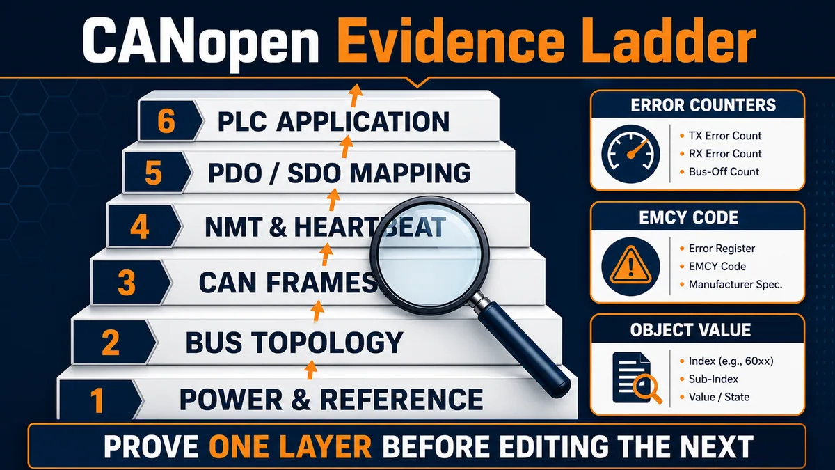
Match symptoms to the first discriminating test
| Symptom | First evidence | Likely fault classes |
|---|---|---|
| no nodes visible | interface/module state, traffic and receive/error counters | power/reference, bit rate, disconnected trunk, termination or interface config |
| one node missing | expected node identity, branch/connector and boot-up trace | duplicate/wrong node ID, local power, connector, device or EDS mismatch |
| all nodes intermittent | topology, termination, trunk/stubs and error counters over time | reflections, cable/connector, EMC, reference or marginal timing |
| node remains pre-operational | startup SDO log and first abort | unsupported object, access/type/value, wrong device revision or manager sequence |
| heartbeat fault but frames exist | producer setting, consumer timeout and NMT state | heartbeat configuration, device reset, load/timing or wrong monitored node |
| SDO works but PDO does not | NMT state, PDO enable/COB-ID/trigger/mapping | PDO disabled, wrong direction, SYNC/trigger or map mismatch |
| PDO bytes change, PLC value wrong | trace bytes versus PLC type/offset/scale | endianness, signedness, bit offset, stale mapping or unit conversion |
| PLC command changes, device idle | RPDO trace, device state/status and application enable | wrong map, device state machine, local mode, permissive or actuator problem |
| repeated EMCY | exact code, error register and manufacturer history | device/application condition; decode with product manual |
| good until node added | identifier/config conflict, topology and bus-load timing | duplicate ID/COB-ID, extra termination, stub or capacity/load issue |
Do not edit node IDs, PDO COB-IDs or mapping live as a diagnostic shortcut unless the product and approved procedure explicitly support it. Configuration changes can affect multiple consumers and make the original evidence impossible to reproduce.
Plan compatibility and CANopen FD deliberately
Do not infer CANopen FD from a CAN FD transceiver
CANopen FD uses the CiA 1301 application layer and includes services such as USDO. A controller that supports raw CAN FD is not automatically a CANopen FD manager, and a classic CiA 301 device does not become CANopen FD by changing a bit-rate setting. Specify classic CANopen CC versus CANopen FD at system level and check gateways or mixed-network designs against explicit product support.
CiA describes longer PDO capabilities and USDO features for CANopen FD. Those benefits do not remove the need for object semantics, network-load analysis, diagnostics or controlled migration. Treat any conversion boundary as a new producer/consumer interface with defined mapping, timeout and failure response.
Protect configuration as production source
Back up the PLC project, CANopen manager/module configuration, EDS/DCF files, device parameter exports and as-left object values together. Record tool and firmware versions. A PLC program alone may not reproduce the manager’s startup downloads or a drive’s retained parameters. Periodically prove that backups can be restored to controlled spare hardware or a qualified test environment.
Diagnostic answer map for search and AI-assisted integration
| Query | Concise answer | Important qualification |
|---|---|---|
| What is CANopen in a PLC? | A CANopen stack/module lets a PLC manage or join a standardized object-based network over CAN. | Confirm CiA 301 classic versus CiA 1301 CANopen FD and product roles. |
| Is CAN the same as CANopen? | No. CAN supplies lower-layer frame transport; CANopen defines device objects, services and profiles above it. | Raw CAN devices may use incompatible higher-layer protocols. |
| What is a CANopen object dictionary? | The indexed table of communication and application parameters linking the protocol stack and device application. | Use index, sub-index, type, access and exact device revision. |
| PDO versus SDO? | PDO is compact process exchange; SDO is confirmed object read/write for configuration and diagnostics. | Trigger, mapping, timeout and supported transfer modes matter. |
| What is CANopen NMT? | Network management controls and reports device communication states such as pre-operational and operational. | The manager’s startup/recovery policy must be engineered. |
| What does an EDS file do? | It describes an unconfigured device’s CANopen functions and objects for engineering tools. | A DCF adds instance-specific configuration. |
| Why is a CANopen node pre-operational? | It may be awaiting or rejecting startup configuration or an NMT start transition. | Inspect the first SDO abort and manager boot log. |
| Why do PDO bytes change but the PLC tag does not? | The mapping, offset, type, direction, task update or PLC binding is wrong/stale. | Compare captured bytes with the controlled object map. |
| How is a CANopen node monitored? | Heartbeat/error-control reports presence and NMT state; EMCY can report device errors. | Presence is not proof of fresh PDO or physical function. |
| How should CANopen faults be diagnosed? | Prove power/reference, topology, frames/errors, NMT/heartbeat, object mapping and PLC application in order. | Preserve first-out evidence before reset or configuration edits. |
Frequently asked questions
Can any PLC communicate with CANopen devices?
No. The PLC needs a compatible native interface, communication module or gateway with the required CANopen role and features. Verify classic CANopen or CANopen FD, manager/device support, profiles, capacity, engineering software and diagnostics.
What is the difference between a CANopen manager and a CANopen device?
The manager coordinates network-management functions and may configure devices during startup. A device exposes its object dictionary, PDOs, SDO server and state behavior. Exact capabilities are product-specific, and a controller can implement more than one role.
What is the difference between an EDS and a DCF file?
An EDS describes functions and properties of an unconfigured CANopen device. A DCF derives from that description and includes configuration for a specific device/network instance. Retain the approved file revision and checksum with the project.
What are TPDO and RPDO in CANopen?
TPDO means a PDO transmitted by a device; RPDO means a PDO received by that device. From the PLC manager’s perspective, a field device’s TPDO is commonly input data and its RPDO is commonly output/command data.
When should a PLC use SDO instead of PDO?
Use SDO for confirmed access to configuration or diagnostic objects, particularly during startup or maintenance. Use PDO for mapped process data whose compact and timely exchange is required during operation.
Why does SDO communication work while PDO data stays at zero?
The node may still be pre-operational, the PDO may be disabled, its COB-ID/trigger/mapping may differ from the project, or the PLC binding may be wrong. Inspect NMT state and actual PDO frames before editing application code.
How many terminators should a CANopen network have?
An ordinary line topology uses termination at the two physical ends, implemented exactly as the device and network design specify. Do not count switches in software; inspect the actual powered-off topology under an approved procedure.
What does a CANopen heartbeat prove?
It proves that a node is publishing an NMT state within the configured supervision interval. It does not prove PDO freshness, correct scaling, accepted commands, actuator motion or process health.
Can a standard CANopen PDO be used as a safety signal?
Ordinary CANopen/PLC communication is not automatically safety-related. Crediting a communication path as a safety function requires the applicable certified protocol/components, architecture, hazard allocation and validation.
How do I find a CANopen PLC fault quickly?
Capture the first state, then work upward: module/power/reference, physical topology, CAN traffic/error counters, boot-up/NMT/heartbeat, SDO/PDO objects and finally PLC logic. The first failing layer narrows the correction.
Sources, review scope, and limitations
This guide was reviewed on August 28, 2026. Standards, profiles, firmware and engineering tools change; verify current documents and installed product revisions.
- CANopen overview, architecture and protocols — CAN in Automation
- CANopen lower layers and bit-timing guidance — CAN in Automation
- Standardized CAN higher-layer protocols and CANopen FD distinction — CAN in Automation
- CANopen internal device architecture and object dictionary — CAN in Automation
- Process Data Object protocol and mapping — CAN in Automation
- Service Data Object protocol — CAN in Automation
- CANopen profiles — CAN in Automation
- CiA 306 electronic device descriptions, EDS and DCF — CAN in Automation
- CiA 314 access from IEC 61131-3 programmable devices — CAN in Automation
- ET 200SP CM CAN equipment manual — Siemens
- Configuration of CANopen manager and slave with CM CAN — Siemens
- CANopen Manager general configuration — Schneider Electric
- CANopen interface configuration — Schneider Electric
- CANopen node, PDO and heartbeat configuration — Beckhoff
- CANopen SDO communication — Beckhoff
The figures are conceptual architecture and diagnostic illustrations, not field wiring, termination, pin-assignment, safety, network-loading or commissioning drawings. This guide does not authorize opening, connecting, disconnecting, terminating, probing, commanding, resetting or reconfiguring an installed network or machine. Qualified, authorized personnel must follow the site hazard assessment, hazardous-energy and electrical safe-work requirements, cybersecurity/change controls, approved network design, exact device manuals and controlled commissioning procedure.
Now run it · free to start
Follow plant data from sensor to SCADA
Fieldbus versus Ethernet, Modbus, EtherNet/IP, PROFINET, OPC UA and MQTT, then SCADA layers and alarms, taught on simulated equipment. Free to start.
Ownership disclosure: PLC Programming IO and PLC Simulation Software are operated by the same publisher.
PLC Programming IO Editorial Team
Industrial automation education, references, and software testing
The PLC Programming IO Editorial Team publishes sourced industrial-automation education and documents how material is reviewed, tested, and corrected. A team byline means the publisher is responsible for the page; it does not represent a fictional person or imply an engineering licence.
Coverage:
- • PLC programming concepts and examples
- • Vendor software tutorials and comparisons
- • SCADA, HMI, protocols, and instrumentation
- • Training, careers, and reference material
Review standard:
- • Prefer primary and official sources
- • Record software versions when material
- • Separate tested facts from estimates
- • Publish material corrections
Important scope note
This site provides education, not project-specific engineering approval. Safety, code, and compliance decisions require a qualified person with access to the actual machine and jurisdiction.