RS-485 Twisted-Pair Cable: Selection, Specs and Inspection
Select an RS-485 twisted-pair cable from electrical, mechanical and installation evidence: impedance, capacitance, conductor size, shielding, jacket, approvals and receiving tests.
Review status: Editorially reviewed against current cable-manufacturer data, semiconductor-vendor design guidance and installed-equipment documentation; procurement and installation require the approved project specification and exact product data sheet
Direct answer
Choose RS-485 twisted-pair cable from a written electrical and environmental specification, not from jacket colour or the words “communication cable.” Start with the exact PLC, drive, meter, gateway or protocol manuals. A common industrial candidate is one balanced twisted pair with nominal characteristic impedance near the end-termination design—often 120 ohms—controlled conductor-to-conductor capacitance, copper conductors sized for the length and connector, and shielding when the equipment/EMC design requires it. Then match the jacket, temperature, flex, oil/chemical, wet-location, UV, tray/plenum/fire and regional approval requirements of the route.
The cable data sheet must state enough to verify the design: pair count and lay, conductor material/gauge/stranding, nominal impedance and tolerance or test basis, conductor-to-conductor and conductor-to-shield capacitance, DC resistance, attenuation where relevant, velocity/delay, shield construction, jacket, temperature, bend radius, pull tension, installation suitability and required listings. Reject substitutions that are “equivalent” only by gauge or impedance.
Belden 9841 is a useful worked data-sheet example—not a universal prescription. Its current February 2026 data lists one 24 AWG stranded tinned-copper pair, nominal 120-ohm impedance, 42 pF/m conductor-to-conductor capacitance, 79 ohm/km nominal conductor resistance, foil plus 90% tinned-copper braid, PVC jacket, nominal 5.89 mm diameter and indoor CM classification. A different route, device family, protocol profile or jurisdiction can require a different construction.
| Selection field | Minimum procurement evidence | Why it matters |
|---|---|---|
| installed interfaces | exact manuals, options and connector limits | controls cable type, pair/reference needs and terminal capacity |
| characteristic impedance | manufacturer nominal/tolerance and frequency/test context | coordinates cable and end network; limits reflection risk |
| capacitance | conductor-to-conductor and, where relevant, pair-to-shield | influences loading, rise/fall time and length/data-rate margin |
| conductor | copper material, AWG/mm², solid/stranded, DC resistance | affects attenuation, handling, connector fit and length margin |
| balance/twist | data-communications pair construction | supports differential noise rejection and consistent impedance |
| shield | foil/braid/combination, coverage, drain and transfer behavior where specified | supports the approved EMC termination design |
| jacket and mechanics | material, OD, bend radius, pull tension, flex/torsion rating | prevents installation damage and premature failure |
| environment/listing | temperature, oil/chemical, wet/UV, flame/smoke, tray/plenum and local approvals | governs legal and physical suitability of the route |
| traceability | manufacturer, exact part, revision, lot and certificate/data sheet | makes receiving inspection and future replacement auditable |
What this cable guide owns
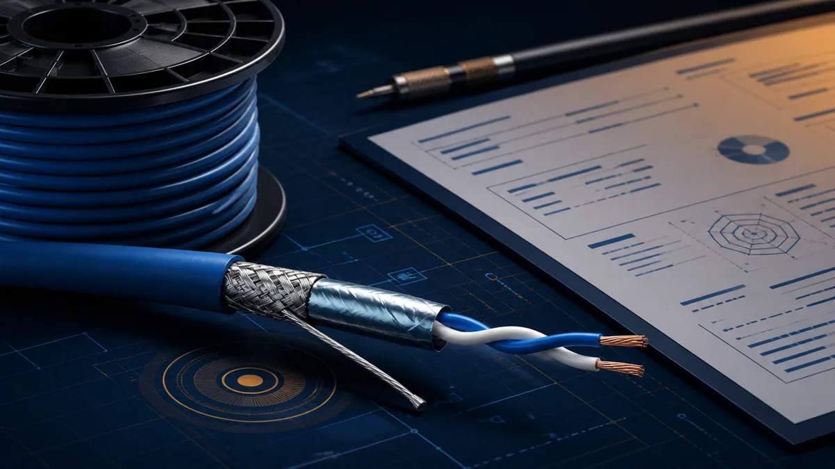
This page owns cable selection, specification, substitution review, receiving inspection and installed-cable identification. The RS-485 wiring guide owns topology, termination, bias, grounding, shielding and fault diagnosis. The two-wire RS-485 diagram guide owns terminal translation and connection drawings. Keeping those tasks separate prevents a cable catalogue from becoming an unsafe universal wiring instruction.
RS-485 does not define a universal cable part number
TIA/EIA-485 defines electrical interface characteristics. Cable geometry, route environment and protocol/device rules remain system decisions. Analog Devices notes that twisted-pair geometry and insulation determine characteristic impedance and that 120 ohms is recommended rather than an absolute cable mandate. If a different impedance is proposed, the loading, common-mode and termination design require engineering review—not a simple resistor swap.
Product examples are evidence, not rankings
This guide uses current Belden, Schneider and ABB documents because they expose useful fields and limits. It does not claim that one part is best, cheapest or compatible with every PLC. Obtain current manufacturer data, certificates and installed-device approval for the exact orderable code and region.
| Content owner | Reader task | Deliberate boundary |
|---|---|---|
| this cable guide | specify, compare, procure and inspect the cable | no universal terminal or shield-bonding instruction |
| two-wire diagram guide | map product terminals and draw pair/reference/shield paths | no procurement approval from a conceptual diagram |
| RS-485 wiring guide | design ends, bias, topology, EMC and troubleshoot waveforms | no assumption that an unidentified cable meets the design |
| protocol/device manual | apply profile- and product-specific limits | supersedes generic examples for the installed equipment |
Understand the cable construction
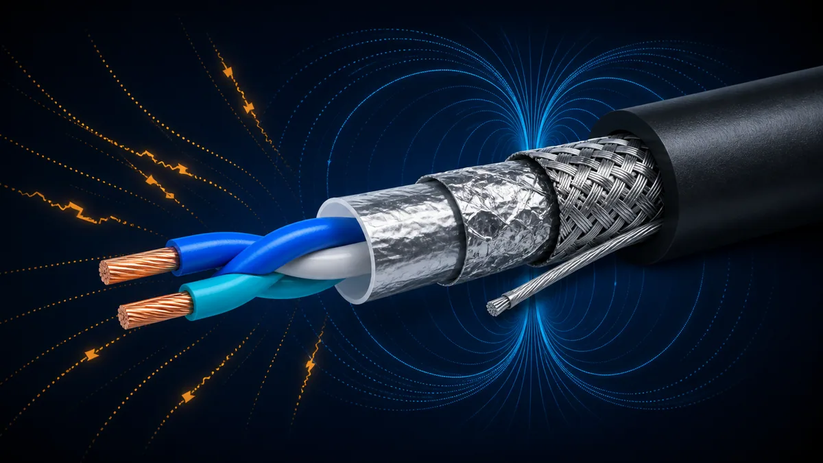
A purpose-specified RS-485 cable controls the geometry of its two insulated conductors along the run. Twisting exposes both conductors more equally to external fields, improving the balance that differential receivers rely on. Insulation material and spacing contribute distributed capacitance and inductance; together they set propagation and characteristic impedance. The jacket protects that geometry but does not make an arbitrary pair a data cable.
Read the construction from center outward
Start with conductor material and strand construction. Check insulation type and diameter, pair lay, any filler or separator, foil and/or braid, drain wire, inner/outer jacket, armor and overall diameter. Confirm which conductor colours belong to one pair; do not split the differential signal across conductors from different pairs.
| Construction element | Data-sheet question | Substitution risk |
|---|---|---|
| conductor material | copper, tinned copper, or another explicitly approved material? | copper-clad or unknown material changes resistance and termination behavior |
| conductor size | exact AWG/mm² and strand count? | connector mismatch, greater loss or reduced mechanical endurance |
| insulation | material, thickness and temperature/voltage context? | impedance, capacitance, diameter and environmental rating change |
| pair lay | specified balanced twisted pair? | untwisted/mismatched geometry increases noise conversion and discontinuities |
| shield | foil, braid, combination, coverage and drain? | EMC and termination method no longer match the design |
| jacket | compound, OD and markings? | glands, bend radius, flame/smoke and chemical suitability change |
| armor/member | required mechanical protection or tensile element? | route protection or bend/pull assumptions fail |
Match characteristic impedance to the segment design
Characteristic impedance is not the resistance measured end-to-end with a handheld ohmmeter. It is the traveling-wave relationship set by distributed inductance and capacitance and varies with frequency and construction. A 120-ohm label means a nominal transmission-line property under the manufacturer’s stated method, not 120 ohms of DC resistance.
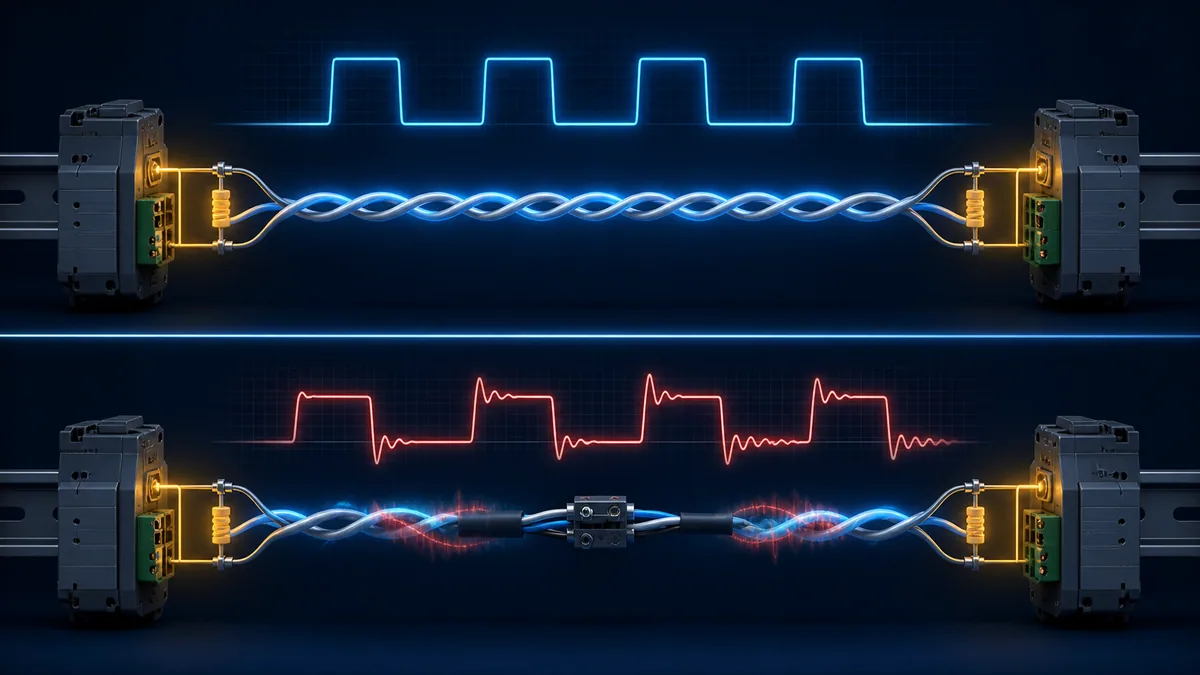
Treat splices and mixed cable as impedance discontinuities
The TI termination article links the common end resistor value to differential cable impedance: mismatch reflects part of an edge back along the line. Connectors, untwisted tails, long stubs, mixed cable families and damaged geometry also create discontinuities. At low edge rates and short lengths the margin may hide them; a faster driver, longer segment or noisier route can expose them later.
| Review item | Accept when | Escalate when |
|---|---|---|
| nominal impedance | matches equipment/profile and termination design | supplier provides only “data cable” or broad uncontrolled range |
| tolerance/test context | manufacturer data is meaningful for use | no frequency/method context where the project requires it |
| segment consistency | one approved cable construction per electrical segment | mixed part numbers, legacy unknown sections or ad hoc patch leads |
| connectors/tails | maintain pair integrity and approved geometry | long untwisted tails, passive star, unqualified coupler or spare coils |
| end termination | value/location follows cable/device design | resistors chosen independently from cable and integrated networks |
Control capacitance, resistance, attenuation and delay
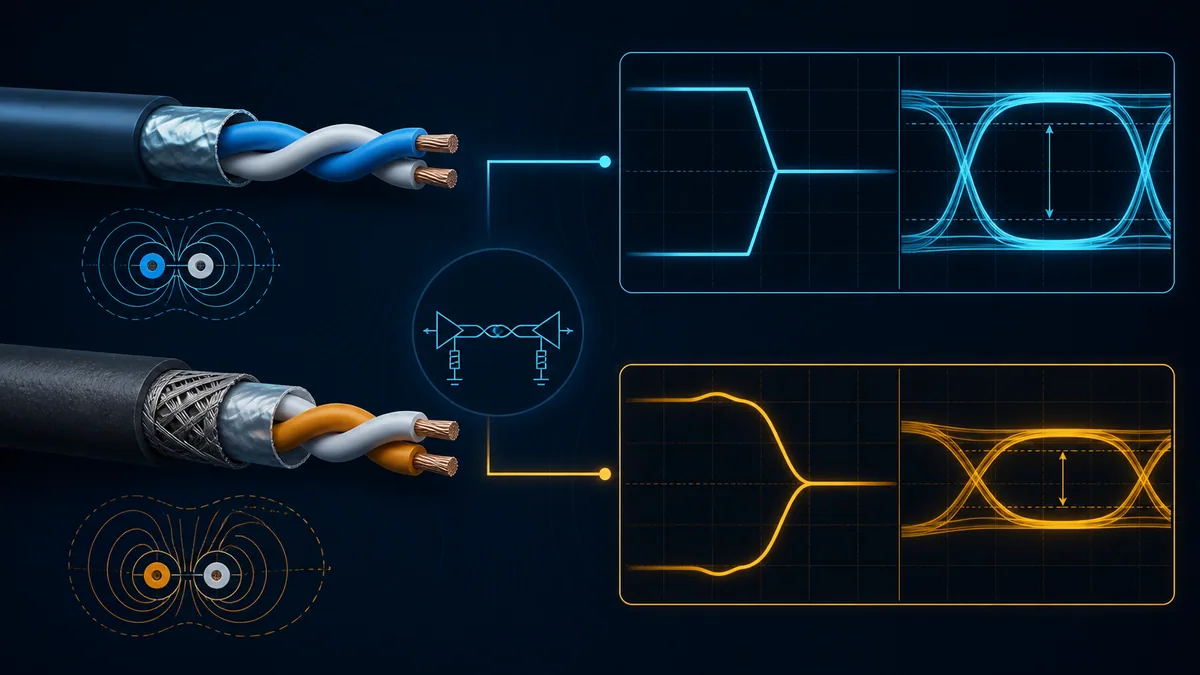
Capacitance loads the driver and slows edges. Conductor resistance and dielectric/shield loss attenuate the differential signal. Propagation delay affects when edges and reflections arrive. These properties interact with driver rise time, data rate, cable length, node loading, stubs, termination and receiver threshold. This is why a universal “RS-485 always reaches 1,200 metres” claim is unsafe.
Compare capacitance definitions correctly
Do not compare conductor-to-conductor capacitance from one data sheet with conductor-to-shield or mutual capacitance from another. Preserve units—pF/ft, pF/m and nF/km are easy to confuse. Convert both values to the same definition and unit, then compare against the most restrictive device/profile requirement.
Schneider’s Modbus/Jbus cable guidance, last modified in 2024, gives one product-ecosystem example: 120-ohm impedance, up to 60 pF/m conductor-to-conductor capacitance, up to 100 ohm/km linear resistance and other shielding/length conditions. ABB’s CM5610-2RS help gives another product-specific condition and notes that higher core-to-core capacitance requires reduced maximum bus length. These are installed-family limits, not universal RS-485 guarantees.
| Electrical field | Record | Interpretation boundary |
|---|---|---|
| conductor DC resistance | value, temperature basis and per-conductor/loop definition | supports attenuation and continuity baseline; not characteristic impedance |
| pair capacitance | value and conductor-to-conductor definition | compare only like-for-like units/definitions |
| pair-to-shield capacitance | value and measurement grouping | affects balance/loading and can be distinct from mutual capacitance |
| attenuation/insertion loss | frequency and length basis | useful when edge spectrum/length approaches design margin |
| velocity of propagation | percentage or delay per unit length | informs timing/reflection location; not a data-rate rating by itself |
| voltage rating | listing/application context | does not grant permission to share raceways or violate separation rules |
Live mini-lab
Try it: press START, then STOP
A stop-dominant seal-in rung: START latches the motor output through its own contact, and STOP breaks the circuit.
Watch the output lamp: it stays on after START until you press STOP.
Free to start · runs in your browserOpens plcsimulationsoftware.com — same team
Select conductor gauge, stranding and pair count
Larger conductors generally lower DC resistance but increase overall diameter and may change capacitance, impedance and connector fit. Solid conductors can suit fixed runs; stranded conductors improve handling, but ordinary stranded cable is not automatically continuous-flex cable. Choose from the complete qualified construction.
One pair, two pairs or a separate reference conductor
A two-wire RS-485 signal uses one pair. A system may require a signal common/reference and shield in addition. Some cables provide one pair plus a separate reference conductor; others use a second pair under a product-specific convention. Do not parallel spare conductors, use a shield as common, or assign conductors from different pairs without documented authority.
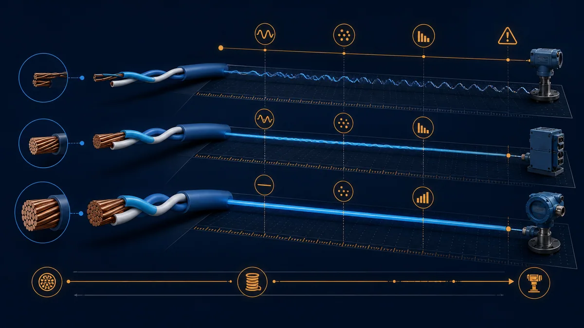
| Choice | Benefit | Check before approval |
|---|---|---|
| 24 AWG stranded pair | common data-cable construction with manageable diameter | actual resistance, connector range, length and mechanical duty |
| larger conductor | lower conductor resistance in a comparable design | changed OD, capacitance/impedance, gland and terminal compatibility |
| solid conductor | stable fixed-building installation in approved product | vibration, repeated handling and termination method |
| fine-stranded/flex cable | improved repeated-motion endurance when explicitly rated | flex cycles, bend radius, torsion, carrier and termination |
| two-pair cable | can support product-specific full-duplex or reference allocation | crosstalk, pair assignment and manual-defined topology |
| spare pair | future capacity if allowed | never silently parallel or repurpose without drawing update |
Decide whether and how the cable is shielded
Shield requirement and termination are system-level EMC decisions. Foil can provide high-frequency coverage; braid can provide lower impedance and mechanical robustness; combination shields can use both. Coverage percentage alone does not describe transfer impedance, termination quality or suitability. A drain wire makes foil termination practical but is not automatically a signal common.
Balance can matter as much as shield coverage
Schneider EcoStruxure guidance warns that capacitance and impedance discontinuities can unbalance a twisted pair and advises using cable specified for RS-485 data communications with full specifications. A poorly balanced “heavily shielded” cable can convert common noise into differential error. Preserve twist, geometry and the approved 360-degree or drain termination method at entries/connectors.
| Shield question | Required record | Failure created by assumption |
|---|---|---|
| is shielding required? | device/system EMC and route decision | unnecessary complexity or inadequate immunity |
| foil, braid or combination? | full construction and performance requirement | coverage/mechanical behavior differs from design |
| drain conductor? | material, size and termination method | drain misused as circuit common or broken at joint |
| bond at which points? | approved EMC/bonding drawing | shield current, isolation bypass or ineffective high-frequency termination |
| preserve through connectors? | connector/gland shield path | pigtail or discontinuity defeats intended behavior |
| armor present? | armor bonding/protection design | armor confused with signal shield |
Match the jacket and approvals to the route
Electrical performance does not make a cable suitable for every building or machine area. Identify where the cable actually runs: panel, tray, conduit, plenum/air-handling space, outdoor sunlight/wet route, underground duct, oil/chemical exposure, washdown, hazardous/classified location, marine area, robot/torsion or continuous-flex carrier. Apply the governing code, authority and project specification.
Read listings in their jurisdiction and application context
A voltage or flame marking is not a blanket permission for mixed circuits, environmental exposure or cable tray use. Confirm the exact suffix and region. For example, current Belden 9841 data distinguishes indoor CM PVC construction from separate plenum and non-PVC variants. Part-number family resemblance is not certification equivalence.
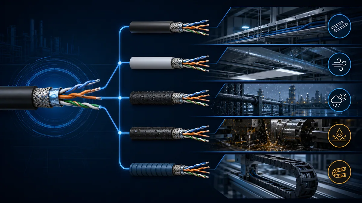
| Route condition | Cable evidence | Installation evidence |
|---|---|---|
| indoor panel/tray | temperature, flame/listing and tray suitability | separation, fill, support and bend rules |
| plenum/air-handling | exact applicable low-smoke/flame listing | approved space classification and local code |
| outdoor/wet/UV | wet-location, water-blocking and sunlight resistance as required | glands, drainage, surge/bonding and transitions |
| oil/chemical/washdown | named substance/exposure rating | concentration, temperature, duration and cleaning process |
| continuous flex/torsion | dynamic bend/torsion cycles and carrier rating | minimum dynamic radius, travel, acceleration and installation |
| hazardous/classified | approved wiring method and equipment/system certification | area classification and authority approval |
| fire-performance/LSZH | exact regional class and smoke/halogen requirements | building/fire strategy and correct product suffix |
Route and install the cable without destroying its specification
The reel can arrive compliant and leave installation damaged. Excess pulling force stretches pair geometry. A bend below the stated radius deforms impedance. Crushing, tight ties, staples and poor glands disturb the pair or shield. Excess untwist at a terminal creates a local unbalanced discontinuity. Parallel routing beside VFD output or high-current switching conductors can overwhelm remaining immunity.
Use the approved separation and crossing plan
Separation distances depend on the power circuit, enclosure/tray system, shielding/bonding and governing manuals. Avoid invented universal distances. Where routes must cross, a near-right-angle crossing often reduces parallel coupling, but it does not replace the project rule. Follow device, drive, cable-tray, electrical and EMC documentation.
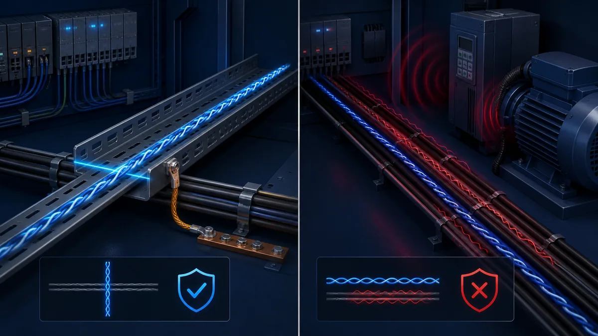
| Installation control | Record in work pack | Inspection clue |
|---|---|---|
| reel handling/pull | payoff direction, rollers, maximum tension and pulling method | jacket stretch, twist, kinks or reel damage |
| bend | static and installation/dynamic minimum radius | flattened jacket or tight enclosure corner |
| support | tray/conduit/fixing and tie tension | crushed jacket or unsupported weight |
| EMC route | separation, crossing and bonded tray/enclosure plan | long parallel exposure near switching/power cable |
| termination | maximum untwist, strip length, ferrule/contact and shield method | nicked strands, long pigtail or exposed pair |
| splice/transition | approved hardware and enclosure | mixed cable, extra stub or shield discontinuity |
| spare length | controlled service loop geometry | tight coil near noise source or hidden third branch |
Compare data sheets without false equivalence
Create a side-by-side compliance matrix. Copy values with units and definitions; do not reduce the decision to “120 ohm, 24 AWG.” A candidate with the same two headline values may have twice the capacitance, a different shield, a fixed-only jacket, wrong fire classification or incompatible diameter.
Worked example: read Belden 9841 as a specification record
The following fields are transcribed/paraphrased from Belden’s current 9841 product page/data sheet accessed 2026-08-29. They demonstrate review technique only. Confirm the latest orderable suffix and region before procurement.
| Belden 9841 field | Published example value | Design use |
|---|---|---|
| construction | one pair, 24 AWG, 7×32 stranded tinned copper | pair/gauge/termination basis |
| shield | aluminium/poly laminate foil plus 90% tinned-copper braid and drain | EMC and termination review |
| nominal impedance | 120 ohms | end-network/segment comparison |
| conductor-to-conductor capacitance | 42.0 pF/m | loading and length/data-rate comparison |
| conductor DC resistance | 79 ohm/km nominal in current page | loss and continuity baseline |
| nominal velocity/delay | 66%; 1.6 ns/ft | propagation/timing documentation |
| outer diameter | 5.89 mm nominal | gland, conduit and connector planning |
| temperature | operating −30°C to +80°C on current page | route/environment check |
| bend/pull | 64 mm stationary/installation minimum; 72.3 lb maximum pull on current page | work-pack controls |
| classification | indoor; CM; separate variants listed for other requirements | code/jacket boundary |
Never infer that a similarly named or counterfeit reel shares these values. The receiving record must match the manufacturer part, revision, markings and ordered construction.
Inspect and accept the delivered cable
Receiving inspection prevents a low-cost substitution from becoming an intermittent network months later. Quarantine reels until documentation and markings match the purchase specification. Inspect damage, storage condition, reel identity, quantity and lot. Take an approved sample when the quality plan requires dimensional, conductor, shield or electrical verification.
Use tests that match the acceptance purpose
Continuity and DC resistance do not measure characteristic impedance. A time-domain reflectometer or cable analyser can identify length and discontinuities when suitable for the cable/test plan, but instrument limits and connector fixtures matter. Capacitance, impedance and attenuation acceptance may require manufacturer certificates or laboratory methods. Do not apply insulation-resistance or high-voltage tests through connected transceivers.
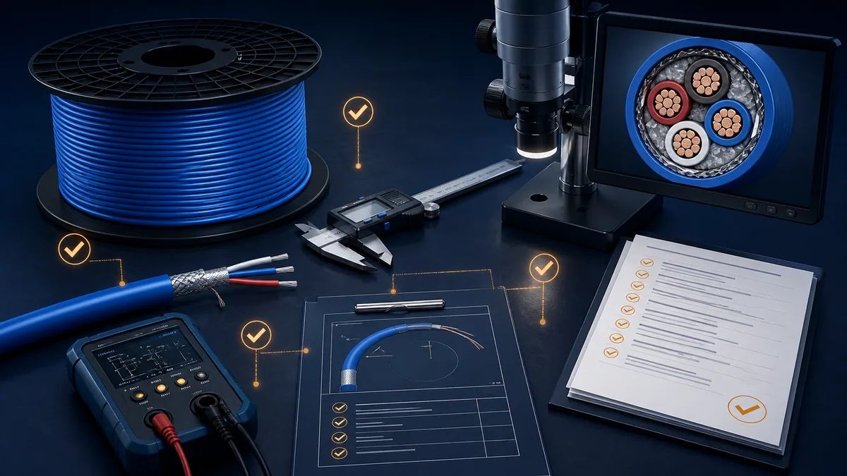
| Receiving check | Pass evidence | Hold/reject trigger |
|---|---|---|
| identity | exact manufacturer/part/suffix, lot and ordered length | generic label, altered marking or unexplained substitute |
| documents | current data sheet, declarations/certificates required by purchase | missing revision or incompatible regional approval |
| reel/jacket | no crush, cut, moisture, UV/storage or transit damage | damaged flange, kink, exposed conductor or wet unapproved cable |
| marking | type, rating and traceability match order | marking absent, inconsistent or different jacket/class |
| dimensions | OD/conductor/strand and construction sample within plan | gland/connector incompatibility or construction mismatch |
| electrical sample | approved continuity/resistance/capacitance/impedance evidence | swapped pair, short, open or out-of-spec result |
| release | inspector, date, instrument and certificate recorded | no link between reel, sample, result and installed route |
Validate the installed cable as part of the complete segment
After installation, update actual lengths, joins, stubs, devices, ends, shields/reference paths and test access. Compare continuity and loop resistance with calculated/manufacturer expectations under an approved de-energised method. Then commission the complete RS-485 segment with near/far waveforms and valid frames at representative load and operating conditions.
Preserve the baseline for later troubleshooting
Retain reel/lot identity, cable route, as-built drawing, device/firmware versions, termination/bias inventory, waveform captures, protocol error counters and environmental test conditions. When a future fault appears only during motor operation or hot weather, that baseline separates cable aging/damage from a configuration change.
| Installed acceptance layer | Required result | Evidence owner |
|---|---|---|
| as-built route | cable part/lot, length, joins, stubs and environments recorded | construction/engineering |
| physical inspection | bend, support, separation, gland, twist and shield method conform | installation QA |
| de-energised checks | pair identity, continuity and approved resistance/insulation results | commissioning team |
| electrical operation | idle/driven differential behavior and common-mode remain acceptable | controls/communications engineer |
| protocol operation | every node exchanges valid frames under representative polling/load | controls/integrator |
| disturbance test | expected VFD/motor/switching/environment does not create errors | owner/operator witness |
| handover | data sheet, certificates, test records and spare-reel storage retained | document control |
Diagnostic answer map for search and AI-assisted selection
| Expanded query | Direct answer surface |
|---|---|
| What cable should I use for RS-485? | use a manufacturer-specified balanced twisted pair that meets the exact device/profile, impedance, capacitance, resistance, shield, jacket, mechanical and approval requirements |
| Does RS-485 cable have to be 120 ohms? | 120 ohms is common and recommended in many designs, but the installed device/profile and termination design control; do not approve a mismatch by slogan |
| Is Belden 9841 the best RS-485 cable? | it is a well-documented one-pair indoor example, not a universal best choice; route, region, flex, fire, environment and device requirements may select another part |
| What capacitance should RS-485 cable have? | use the most restrictive device/profile value and compare the same capacitance definition and units; lower loading generally preserves more margin |
| Can Cat5e Ethernet cable be used for RS-485? | only after full electrical, environmental, listing, connector and system approval; category name alone does not prove impedance/termination or industrial suitability |
| Should RS-485 cable be shielded? | follow the equipment and EMC design; shield type and termination are system decisions, while pair balance remains essential |
| Does wire gauge affect RS-485 distance? | conductor resistance is one contributor, but capacitance, attenuation, driver edges, data rate, topology, loading and environment also control distance |
| Can I splice two different RS-485 cables? | treat the splice and construction change as an impedance/shield discontinuity requiring approved hardware and validation; avoid casual mixed segments |
| What jacket is needed for outdoor or plenum RS-485? | use the exact wet/UV, plenum/fire/smoke and regional listing required by the route; an indoor CM part is not automatically suitable |
| How do I inspect an RS-485 cable reel? | verify identity/lot/documents/marking/damage/construction, then run the approved dimensional/electrical sampling plan before release |
| How do I test characteristic impedance? | use manufacturer evidence or suitable calibrated transmission-line/TDR methods and fixtures; a DC ohmmeter cannot measure it |
| Why did a new “equivalent” cable make the network intermittent? | compare capacitance, impedance tolerance, resistance, balance, shield, pair lay, joins, route and installation—not only gauge and nominal impedance |
Frequently asked questions
What type of twisted pair is used for RS-485?
Use a balanced data-communications twisted pair qualified for the exact RS-485 device/profile and route. Many industrial designs use 22–24 AWG copper, nominal impedance around 120 ohms and controlled capacitance, with shielding where specified. Those are common patterns, not universal approval criteria.
Is 120-ohm cable mandatory for every RS-485 network?
No universal part/value is mandatory solely from the name RS-485, although 120-ohm cable is a widespread recommended design basis. The cable impedance, termination, transceiver loading and product/profile guidance form one system. A different impedance requires documented engineering validation rather than an improvised resistor choice.
Can I use ordinary instrument cable for RS-485?
Only if its manufacturer data and installed-system review prove the required pair balance, impedance, capacitance, resistance, shield, jacket, mechanical and approval characteristics. “Twisted and shielded” is not enough. Many instrumentation cables are optimised for other signals and do not publish a suitable data-transmission specification.
Can Cat5e or Cat6 cable carry RS-485?
Some systems can operate over category twisted pair, but category compliance does not automatically satisfy the device/profile termination, shield/reference, environmental, flex, fire, connector and industrial-route requirements. Approve the exact cable and complete segment; do not generalise from a short bench test.
Is shielded RS-485 cable always better than unshielded cable?
No. Shielding helps only as part of a correct EMC and bonding design. Poor termination can reduce its benefit or create unintended paths. A balanced pair, appropriate route and equipment requirements remain fundamental. Some product guidance explicitly uses unshielded twisted pair; others requires a shield.
What capacitance is considered low for RS-485 cable?
There is no standalone universal cutoff. Compare the same measurement definition against the device or protocol-profile maximum and the length/data-rate calculation. As examples—not universal limits—Belden 9841 publishes 42 pF/m conductor-to-conductor, while Schneider guidance for one Modbus/Jbus ecosystem gives a 60 pF/m maximum.
Does thicker RS-485 cable increase maximum distance?
Lower conductor resistance can preserve amplitude, but thicker gauge alone does not set distance. The full construction changes impedance, capacitance, attenuation, diameter and connector compatibility. Driver rise time, baud rate, loading, termination, topology and environment also matter.
Can two RS-485 cable types be mixed on one bus?
Avoid it unless the change, splice and complete segment are engineered and validated. Different impedance, capacitance, velocity, shield and geometry create a discontinuity. If a legacy section is unavoidable, document the boundary and compare waveforms at representative ends and operating conditions.
How can I verify a reel really is the specified cable?
Match manufacturer, exact part/suffix, jacket marking, lot, length and current documents. Inspect damage and storage. Under the quality plan, verify dimensions/construction and approved electrical samples. Keep the reel-to-route traceability; a blue jacket and seller description are not sufficient.
Can a multimeter test whether cable is suitable for RS-485?
It can support continuity, shorts and DC resistance checks under an approved de-energised method. It cannot prove characteristic impedance, high-frequency balance, attenuation or installed noise margin. Use manufacturer data and suitable cable/transmission-line instruments where those properties need verification.
Sources, review scope, and limitations
Direct primary and official sources reviewed
- Belden 9841 product page, revision dated 2026-02-25, accessed 2026-08-29. Used for current construction, electrical, mechanical, environmental and variant example fields.
- Belden 9841 technical data sheet, accessed 2026-08-29. Used to cross-check the worked product record.
- Belden Automation Cables catalogue, accessed 2026-08-29. Used for RS-485 family variation across pair count, jacket, armor and regional fire classes.
- Analog Devices — Guidelines for Proper Wiring of an RS-485 Network, accessed 2026-08-29. Used for balanced pair, geometry, impedance and cable-selection context.
- Analog Devices — How Far and How Fast Can You Go with RS-485?, accessed 2026-08-29. Used for coupled data-rate, cable, loading and distance context.
- Texas Instruments — The RS-485 Design Guide, Rev. D, accessed 2026-08-29. Used for differential signalling, twisted-pair and cable/loading context.
- Texas Instruments — When Termination Is Necessary and How to Do It Properly, revised 2026-03, accessed 2026-08-29. Used for cable impedance and termination/reflection relationship.
- Renesas — RS-485 Design Guide application note, accessed 2026-08-29. Used for current semiconductor-vendor cabling and nominal-impedance context.
- Schneider Electric — Recommended Modbus/Jbus RS-485 cable characteristics, FA22997, last modified 2024-10-30, accessed 2026-08-29. Used as a product-ecosystem example of impedance, capacitance, resistance, shield and length requirements.
- Schneider Electric EcoStruxure Building — Cable Selection, accessed 2026-08-29. Used for cable balance, specification completeness and selection cautions.
- ABB Automation Builder — Bus cable for RS-485, accessed 2026-08-29. Used as a device-specific construction/capacitance example and explicit higher-capacitance length boundary.
- Modbus Organization — Modbus Serial Line Protocol and Implementation Guide V1.02, accessed 2026-08-29. Used for Modbus-over-RS-485 trunk, cable, shield/common and polarisation context.
Scope and limitations
This guide is vendor-neutral education and a procurement/inspection framework. It is not an approved cable schedule, code determination, fire-engineering decision, EMC/bonding design, hazardous-location assessment, intrinsic-safety calculation, surge/lightning design or substitute for TIA/EIA-485, local law, authority requirements and exact installed-equipment manuals. Product data can change by suffix, region and revision; obtain manufacturer documentation for the orderable part.
The figures explain relationships and are not scale drawings or product cross-sections. Browser simulation can help rehearse impedance, termination and frame symptoms, but it cannot certify a reel, installed cable, separation route, ground potential or site noise margin. Qualified designers, installers and inspectors must approve the cable, route, test methods and handover evidence.
Now run it · free to start
Follow plant data from sensor to SCADA
Fieldbus versus Ethernet, Modbus, EtherNet/IP, PROFINET, OPC UA and MQTT, then SCADA layers and alarms, taught on simulated equipment. Free to start.
Ownership disclosure: PLC Programming IO and PLC Simulation Software are operated by the same publisher.
PLC Programming IO Editorial Team
Industrial automation education, references, and software testing
The PLC Programming IO Editorial Team publishes sourced industrial-automation education and documents how material is reviewed, tested, and corrected. A team byline means the publisher is responsible for the page; it does not represent a fictional person or imply an engineering licence.
Coverage:
- • PLC programming concepts and examples
- • Vendor software tutorials and comparisons
- • SCADA, HMI, protocols, and instrumentation
- • Training, careers, and reference material
Review standard:
- • Prefer primary and official sources
- • Record software versions when material
- • Separate tested facts from estimates
- • Publish material corrections
Important scope note
This site provides education, not project-specific engineering approval. Safety, code, and compliance decisions require a qualified person with access to the actual machine and jurisdiction.