2-Wire RS-485 Wiring Diagram: PLC, Gateway and Field Devices
Build and verify a two-wire RS-485 connection from the installed manuals: translate terminal names, draw the shared pair, handle 4-wire ports, reference and shield paths, then prove the finished link.
Review status: Editorially reviewed against current manufacturer, semiconductor-vendor and Modbus Organization guidance; every installed terminal and protection detail still requires the exact device manual and approved drawing
Direct answer
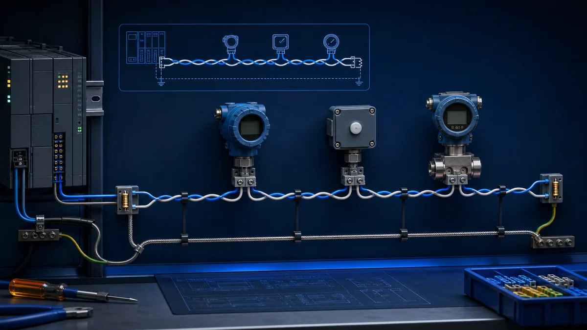
A basic two-wire RS-485 wiring diagram has one shared differential pair running as a continuous trunk through every device. At each node, one documented data conductor lands on the terminal the manufacturer defines as one side of the differential signal, and the other conductor lands on its complement. The phrase “two-wire” counts the signal pair; the approved installation may also require a signal-reference/common conductor, cable shield, protective bonding, isolation or surge protection. Termination, if required by the installed design, belongs at the two physical ends of each electrical segment. Bias or line polarisation belongs at one coordinated location unless the exact transceivers already provide the required idle-state behaviour.
Do not draw or wire the circuit by assuming that A, B, +, −, D0 and D1 mean the same thing on every product. Build a terminal-translation table from both manuals first. A selectable four-wire port can operate with a two-wire device only when its documentation explicitly permits two-wire half-duplex mode and defines how its same-polarity transmit and receive terminals are joined. Connector pin numbers are product-specific.
The safest reusable diagram is therefore a controlled template, not a universal pinout:
| Drawing path | What the drawing must show | What must come from the installed manual |
|---|---|---|
| shared differential pair | one continuous twisted pair through the nodes | exact terminal labels, electrical definitions and connector pins |
| signal reference/common | a separate intentional path where specified | whether it is required, isolated, internally connected or bounded |
| shield and bonding | shield continuity and approved termination points | gland, chassis, bonding and EMC practice for the system |
| end networks | termination only at the actual segment ends when required | internal switches, external values, active networks and power dependency |
| line polarisation | one coordinated idle-state strategy | internal fail-safe capability, external resistor values and location |
| port mode | two-wire half-duplex and direction control | switch, jumper, software mode and turnaround behaviour |
What this page owns—and what the broader guide owns
This page is the implementation owner for people who need to turn two or more product manuals into a connection drawing. It covers native two-wire terminals, selectable four-wire ports, terminal translation, drawing fields, diagram review and point-by-point verification. The broader RS-485 wiring, termination and troubleshooting guide owns the deeper design and fault-diagnosis decisions for termination, biasing, grounding, shielding, cable length, topology and waveform interpretation.
Keep the query variants on one diagram owner
“RS-485 2 wire,” “two-wire RS-485 connection,” “RS-485 half-duplex wiring” and “2 wire RS-485 wiring diagram” normally ask for the same installation artifact. Publishing separate keyword-swapped articles would split links and force search engines and readers to choose between nearly identical answers. This canonical answers the variants as sections, tables and FAQs while the broader physical-layer guide remains distinct by task.
RS-485 is not the application protocol
RS-485 defines electrical signalling, not device addresses, register meanings or message framing. Modbus RTU, BACnet MS/TP and proprietary serial protocols may use a two-wire RS-485 physical layer, but each adds its own role, timing and configuration rules. A correct cable can still show no application response when baud, parity, address, function or register mapping is wrong. Keep physical and protocol acceptance evidence separate.
| Owner | Primary question | Included | Excluded or linked onward |
|---|---|---|---|
| this diagram guide | exactly what should be connected and documented? | pair, common, shield, terminal translation, port conversion, node order | detailed resistor design and waveform diagnosis |
| RS-485 wiring guide | why does the physical network work or fail? | topology, termination, bias, EMC, length, commissioning | product-specific universal pinout |
| Modbus guide | is the serial request and response valid? | address, function, CRC, timing and exception evidence | general RS-485 construction approval |
| installed manuals | what is correct for this equipment? | connector, terminal, mode, limits and safeguards | vendor-neutral assumptions |
Read the two-wire diagram correctly
Two-wire half-duplex uses one differential signal path in both directions. The controller drives a request, releases the line, and the addressed device drives a response. Other devices keep their drivers disabled. Receivers can listen while the pair is idle or active, but only the intended transmitter should control the segment at a given time.
“Two-wire” can still mean more than two conductors
The name describes the differential data pair. A cable or terminal block may also include COM, SG, SC, REF, drain/shield and protective-earth provisions. A reference conductor is not automatically the cable shield. The shield is not automatically protective earth. A drawing that shows only two coloured strokes may be adequate for a conceptual block diagram but inadequate for fabrication or commissioning.
Direction control is part of the connection contract
Many PLC modules and gateways control their driver automatically after two-wire mode is selected. Other interfaces expose a transmit-enable function or rely on adapter timing. The driver must release early enough for the response and not so early that it truncates the request. The Analog Devices AN-960 implementation guide depicts two-wire RS-485 as a multipoint half-duplex configuration with multiple drivers and receivers on the same signal path. That electrical model is why transmit ownership matters.

| Bus phase | Expected driver state | Evidence to record | Failure clue |
|---|---|---|---|
| idle | no application transmitter active; documented idle strategy holds the line | stable idle waveform and no random characters | floating state, unexpected transmitter or interference |
| request | controller/client driver active | request reaches near and far ends without severe distortion | polarity, continuity, topology or client-port issue |
| turnaround | request driver releases before response begins | clean interval appropriate to the protocol/device | collision, clipped final byte or late response |
| response | one addressed server/device driver active | response exists at the device and returns to client | target configuration, driver enable or return-path issue |
| recovery | all drivers return to expected idle state | counters remain stable over repeated exchanges | stuck transmitter or unintended second controller |
Build a terminal-translation table before the schematic
Terminal letters are labels, not proof of electrical polarity. Some manuals define A as inverting or negative; others associate A with positive or non-inverting. Protocol documents can introduce their own D0 and D1 convention. Treat each endpoint as a translation exercise.
Translate definitions, not typography
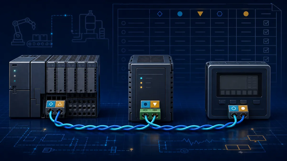
For every device, record the catalogue number, hardware option, manual document number/revision, connector, pin, printed terminal name, manual’s electrical description and selected port mode. Then assign neutral project conductor names such as PAIR_1 and PAIR_2. Connect only when two device definitions map to the same conductor meaning.
The current Schneider PM8000 help, for example, describes − as data minus/inverting, + as data plus/non-inverting and C as common for that product family. That is useful product evidence, not permission to reinterpret another vendor’s A and B without its manual.
| Device record field | Record content | Acceptance rule |
|---|---|---|
| exact device identity | model, option and serial interface | matches the installed nameplate and approved bill of materials |
| source document | manual identifier, revision and page | direct manufacturer source retained with project records |
| physical point | connector name and pin or terminal | connector view orientation is explicit |
| printed label | exact case and symbols from the product | never silently normalised to another vendor’s convention |
| electrical definition | plus/minus, inverting/non-inverting, D0/D1 or TX/RX | definition is quoted or paraphrased accurately from the manual |
| project conductor | neutral pair member and colour | consistent at every node and shown in the cable schedule |
| port mode | two-wire, half-duplex, automatic direction or approved equivalent | configuration export or switch position retained |
| verification | continuity, visual inspection and controlled communication test | signed result and restoration status recorded |
Do not trust cable colour or connector shape
RS-485 does not assign a universal conductor colour. Nor does a DB-9, RJ-style or removable terminal connector imply a universal RS-485 pinout. The same shell can carry RS-232, RS-422, two-wire RS-485, four-wire RS-485, power or manufacturer-specific signals. Draw the connector from the equipment-facing or cable-facing perspective explicitly; confusing those views mirrors the pins.
Live mini-lab
Try it: press START, then STOP
A stop-dominant seal-in rung: START latches the motor output through its own contact, and STOP breaks the circuit.
Watch the output lamp: it stays on after START until you press STOP.
Free to start · runs in your browserOpens plcsimulationsoftware.com — same team
Draw a native two-wire multidrop connection
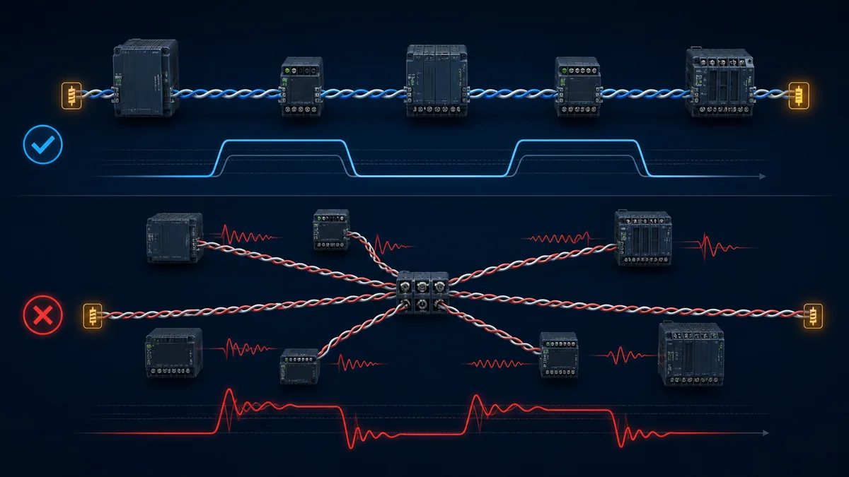
Start with one horizontal trunk, then place devices in physical cable order. Show the pair entering and leaving intermediate terminals or junctions without creating long branches. Mark the two physical segment ends. Add the documented reference and shield paths separately. Only after the topology is clear should the drawing show termination and bias components.
A practical drawing sequence
- Identify every device, connector and port mode from the approved manuals.
- Choose neutral project names for the two signal conductors.
- Draw one continuous trunk in real physical order, including repeaters as boundaries.
- Add each node’s very short approved connection to the trunk.
- Add common/reference, shield and protective bonding as distinct paths.
- Mark actual electrical ends and every internal or external termination network.
- Mark the single coordinated bias/polarisation source or documented internal fail-safe strategy.
- Add cable type, route/segment length, stub length, connector view and drawing revision.
- Add a note that each terminal definition is controlled by the cited device manual.
- Review the drawing against the installed configuration before any energised test.
| Drawing element | Correct representation | Review question |
|---|---|---|
| trunk | continuous pair in physical route order | can a reviewer identify both ends without guessing? |
| intermediate node | pair enters/leaves with the shortest approved local connection | is any hidden branch longer than the device guidance permits? |
| repeater/isolator | explicit segment boundary with two separately reviewed sides | are termination, bias and reference decisions repeated per segment? |
| removable plug | continuation and maintenance effect shown | does unplugging this node interrupt downstream devices? |
| internal resistor switch | component and switch state recorded | is it powered, passive, combined with bias, or product-specific? |
| temporary adapter | shown only on test revision and removed on final as-built | can it add a third end, bias source or termination? |
Termination is a design decision, not a decorative symbol
Parallel termination commonly approximates the cable’s differential characteristic impedance and is placed at the physical ends when required. Two nominal 120-ohm end resistors are common in industrial RS-485, but the installed cable, edge rate, device instructions and integrated networks control the real value and need. The Texas Instruments termination guidance explains the relationship between characteristic impedance, reflections and termination. Do not add a resistor at every node or assume the logical controller is always a physical end.
Bias must be coordinated with termination and receiver behaviour
External pull-up/pull-down networks establish an idle differential state in designs that need them. Several devices with enabled bias networks can overload or shift the bus. Modern receivers may provide open, short or idle fail-safe behaviour. The schematic should identify the approved strategy, not simply repeat generic resistor values copied from the internet.
Connect a selectable four-wire port to a two-wire device
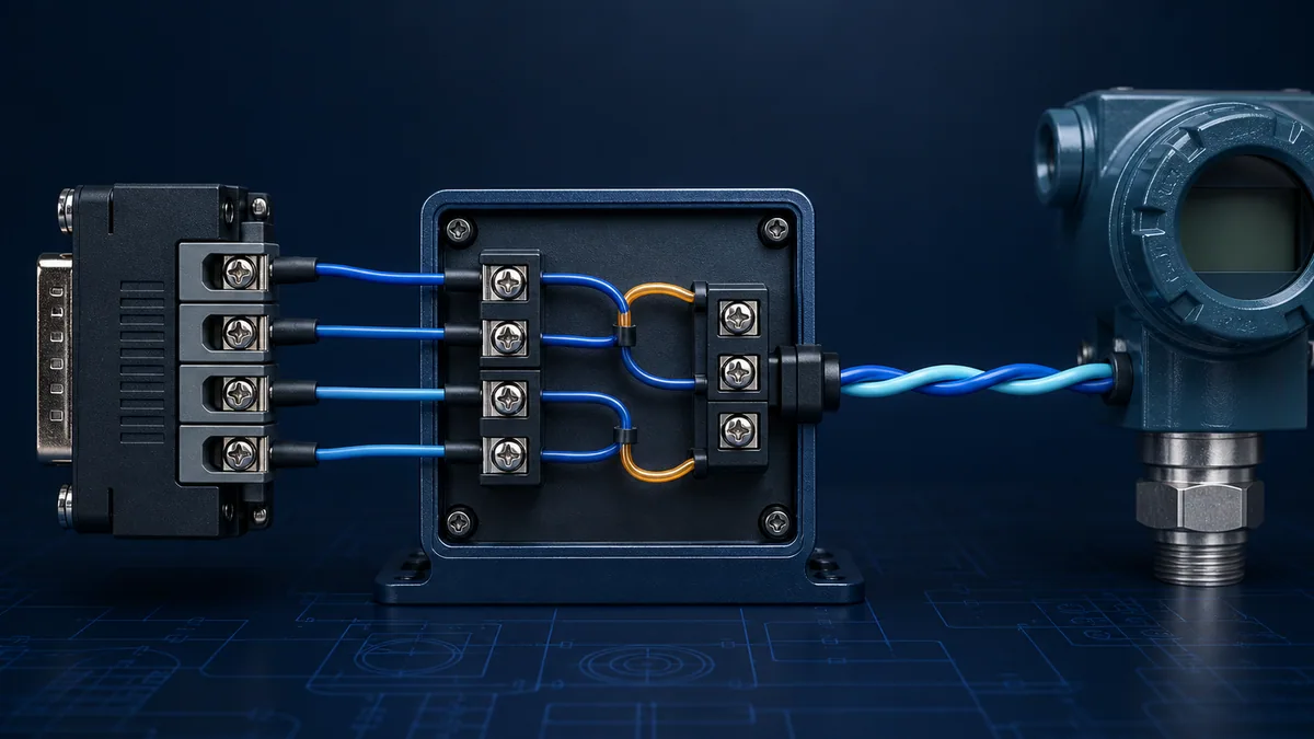
A four-terminal serial interface often exposes separate transmit and receive pairs. Some products permit those same-polarity paths to be joined so the port can operate as a two-wire half-duplex interface. Others require a switch or software selection; some RS-422-only ports cannot release their driver and are unsuitable for a multidrop two-wire bus.
Use the manufacturer’s two-wire mode instructions
NI’s current support procedure for its applicable RS-485 hardware instructs users to join TXD+ with RXD+, join TXD− with RXD−, connect the resulting pair to the two-wire device, select the two-wire automatic mode and verify with a supported command. NI also publishes different connector pin pairs for DB-9, DB-25 and RJ-50 hardware, which demonstrates why a generic drawing must not supply universal pin numbers.
The reusable logic is “same documented polarity together,” not “pin X always joins pin Y.” Confirm that the product is an RS-485 interface capable of tri-stating its driver, not merely a four-wire RS-422 transmitter.
| Source-port finding | Two-wire decision | Required proof |
|---|---|---|
| explicit two-wire RS-485 mode with jumper diagram | follow the exact manual mapping | switch/software mode, jumper continuity and communication test |
| TX+/TX− and RX+/RX− with stated two-wire support | join same documented polarity as instructed | connector orientation and product pinout verified |
| four-wire RS-485 only, no two-wire statement | do not infer a jumper arrangement | manufacturer confirmation or approved converter |
| RS-422-only transmitter | do not place directly on a multipoint two-wire bus | use suitable RS-485 hardware that can release the line |
| automatic direction converter | test turnaround at actual baud/frame timing | complete request, clean release and complete response |
| selectable termination/bias inside adapter | include its state in segment inventory | network values and power dependency documented |
Add reference, shield and bonding without conflating them
Differential signalling rejects noise common to the pair, but receivers still have common-mode limits. A signal-reference conductor can keep endpoint voltages within that range when required. A shield intercepts or redirects electromagnetic coupling according to the EMC design. Protective earth and equipotential bonding serve safety and installation functions. They are related design elements, not synonyms.
Follow the most specific approved system guidance
The current Schneider PM8000 wiring guidance calls for a data +, data −, a C common and a shield connection for that family. The Modbus Serial Line implementation guide presents a common conductor and shield/polarisation guidance for its ecosystem. Other isolated products can differ. Use the product and system documents that actually govern the installation.
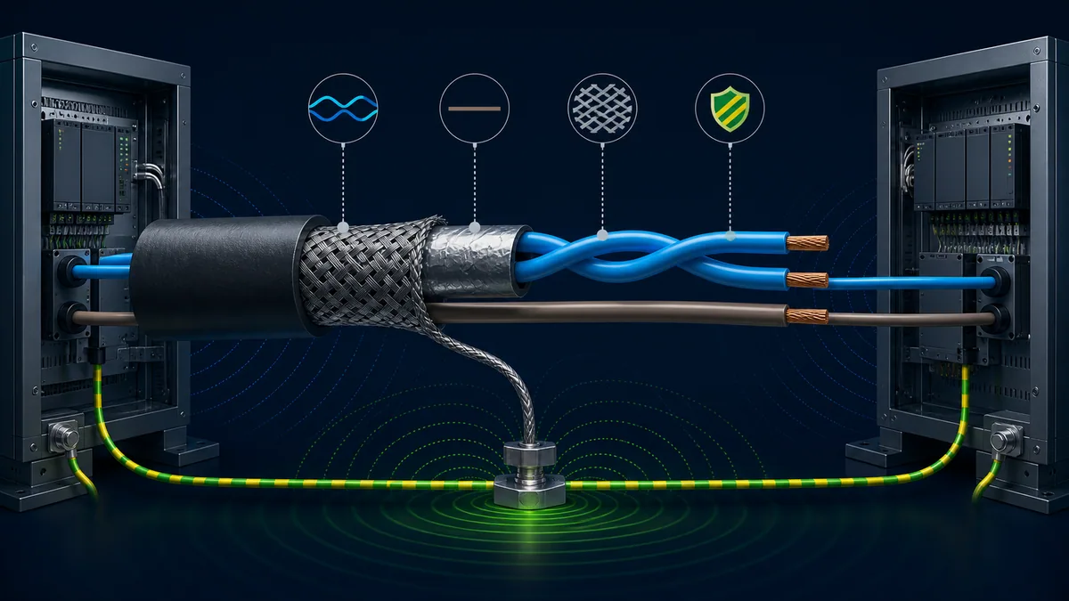
| Path | Purpose in the reviewed design | Diagram mistake to reject |
|---|---|---|
| twisted differential pair | carries the balanced signal | splitting the conductors across different pairs or excessive untwist |
| signal common/reference | manages endpoint common-mode relationship where specified | omitting it or substituting shield without authority |
| cable shield/drain | supports the approved EMC coupling/bonding strategy | using it as an undocumented signal-current path |
| protective earth/bond | supports safety and equipotential bonding | treating circuit common as interchangeable with PE |
| isolated boundary | interrupts a direct current path while transferring information | bypassing isolation with an accidental common, shield or power path |
| surge protection | limits specified transient energy when engineered | adding generic protection with incompatible capacitance or earth path |
Verify the drawing before energisation
A good schematic is inspectable. A second qualified reviewer should be able to trace every conductor from the controller through each device to the far end, identify the source for every terminal definition and state which components depend on device power. Resolve contradictions while the design is still paper, not while swapping conductors on live equipment.
Perform a controlled document and continuity review
Under the site’s approved isolation and test procedures, compare the approved drawing, cable schedule, installed terminal markings and manufacturer manuals. Verify connector orientation. Confirm pair continuity and absence of unintended shorts using methods permitted by the equipment. Do not apply an ohmmeter to an energised network. Do not megger through connected electronics unless the equipment and test plan explicitly allow it.
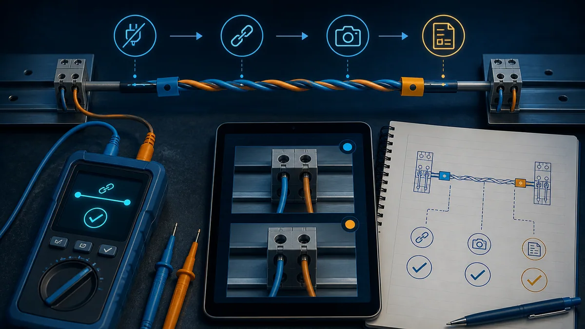
| Pre-energisation check | Pass evidence | Stop condition |
|---|---|---|
| identity | every installed device and serial option matches the drawing | substitute model, unknown option or undocumented converter |
| connector view | pin orientation and mating side explicitly identified | mirrored or ambiguous connector drawing |
| pair mapping | each endpoint maps through its own manual to the project pair | A/B assumption without electrical definition |
| topology | node order, ends, stubs and repeaters match the route | hidden star, long branch or unrecorded junction |
| termination/bias | all internal and external networks inventoried | unknown switch state or more networks than design |
| reference/shield | paths and isolation/bonding intent match approved design | shield used as an accidental common or isolation bypass |
| safe test state | isolation, permits, hazards and restoration steps approved | live/unknown energy or unapproved test method |
Commission the connection with layered evidence
Start with the smallest approved segment: controller or test interface, one target, correct two-wire mode and documented end networks. Prove the request and response before adding nodes. Then add devices or segments in controlled increments. A change that causes errors is evidence; do not erase it by changing several configuration and wiring variables together.
Capture four boundaries for a no-response fault
Observe whether the request exists at the controller, reaches the target, produces a response at the target and returns to the controller. This four-boundary method separates a missing request, damaged outbound path, target rejection, target driver problem and damaged return path. Use suitably rated, isolated instruments and approved connection practices for the environment.
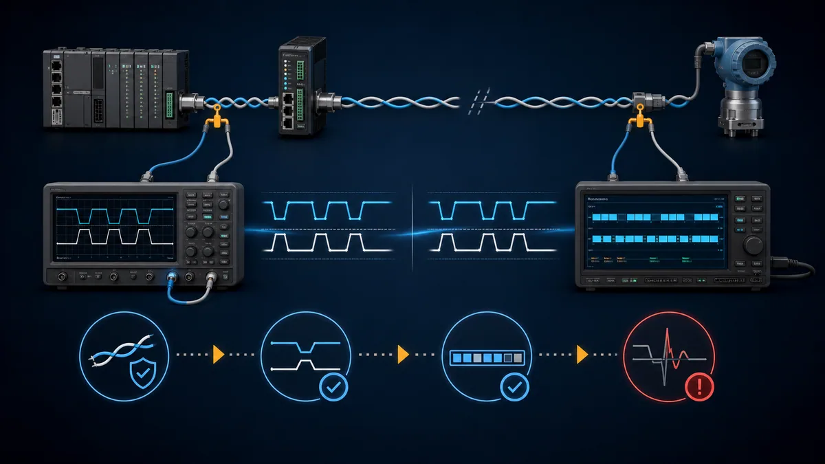
| Evidence boundary | Expected result | If absent or damaged |
|---|---|---|
| controller terminals during request | complete differential request with intended timing | confirm port, mode, driver control, configuration and local connector |
| target terminals during request | recognisable request reaches the target | trace pair continuity, polarity translation, trunk, ends and intermediate hardware |
| target terminals during response | one response driver activates after accepted request | check serial format, address, protocol validity, target mode and driver enable |
| controller terminals during response | response returns with usable waveform | inspect return path, contention, termination, common-mode and receiver settings |
| decoded transaction | frame fields and checks are valid | separate physical integrity from protocol/application mapping |
| repeated loaded run | error counters and response times remain within acceptance limits | correlate failures with node additions, switching, load and environment |
Close with an as-built acceptance record
Record the final node order, connector/pin mapping, cable and segment lengths, stub lengths, termination and bias locations, port modes, serial parameters, shield/reference design, device/firmware identities and baseline captures. Remove temporary adapters and test jumpers. Restore covers, protections and normal control ownership. The drawing is not finished until it matches the installed and accepted state.
Common diagram mistakes and corrective decisions
The most dangerous drawings look plausible while hiding assumptions. A straight line labelled A/B can conceal reversed vendor conventions. A shield symbol can conceal an unintended current path. A termination symbol beside the controller can conceal the fact that the controller sits halfway along the trunk.
Diagnose the drawing before diagnosing the bus
When a network fails, annotate the as-built diagram with measured evidence rather than redrawing it from memory. Mark the first boundary where the request disappears or the last boundary where the response exists. Record which node addition changes the failure. This makes the next test falsifiable.
| Diagram or installation symptom | Likely drawing defect | Corrective action |
|---|---|---|
| no node responds after new cable | terminal meanings or port mode assumed | rebuild the translation table and verify request at both ends |
| only one brand of device fails | vendor label convention not translated | map its manual definition to neutral project conductors |
| network works only with a service adapter attached | adapter supplies bias, termination, reference or receiver path | inventory the adapter and engineer the required permanent function |
| far nodes fail at higher speed | trunk/stub/end details omitted | update as-built lengths/topology and review physical design |
| errors begin when an intermediate node is unplugged | connector secretly interrupts onward trunk or powers an end network | show connector continuation and power dependency explicitly |
| several devices work individually but not together | duplicate bias/termination, address conflict or loading hidden | add all internal networks and addresses to the schedule |
| polarity swap appears to fix one device and break another | inconsistent terminal translation | stop trial-and-error and define each endpoint electrically |
| shield change alters communication | common-mode or unintended return path hidden | review reference, isolation, bonding and EMC paths as a system |
Diagnostic answer map for search and AI-assisted troubleshooting
These expanded questions keep related two-wire connection intent on one evidence-rich canonical surface.
| Expanded query | Direct answer surface |
|---|---|
| How do I draw a two-wire RS-485 wiring diagram for a PLC and meter? | build a terminal translation from both manuals, draw one shared twisted-pair trunk in physical order, then add documented common, shield, end and bias paths |
| Is two-wire RS-485 half duplex? | normally yes: the same differential pair carries request and response at different times, so driver control and turnaround must be correct |
| Does two-wire RS-485 need a third ground wire? | the pair count excludes the reference/common; include the separate path or isolation strategy required by the exact equipment and system design |
| Is RS-485 A positive and B negative? | not universally; use each manual’s plus/minus, inverting/non-inverting or D0/D1 definition and map it to neutral conductor names |
| How do I connect a four-wire RS-485 port to two wires? | only when the port supports it: follow its manual to join same-polarity TX/RX terminals and select the documented two-wire mode |
| Can an RS-422 port be jumpered for two-wire RS-485? | not by assumption; an RS-422 driver may not release a multipoint bus, so use explicitly compatible hardware or manufacturer direction |
| Where do termination resistors go on a two-wire diagram? | at the actual electrical segment ends when the cable/device design requires them, including each side of a repeater as separate segments |
| Where does the RS-485 bias network go? | at one coordinated location unless documented internal fail-safe behaviour provides the required idle state |
| Should the shield be the RS-485 common conductor? | not automatically; shield, circuit reference and protective bonding have different purposes and must follow the approved manuals/design |
| How do I prove a two-wire RS-485 drawing is correct? | verify identity, connector view, terminal definitions, continuity and networks, then capture request and response at controller and target boundaries |
| Why does a two-wire RS-485 link transmit but not receive? | verify port mode and direction release, then prove request at target and response at target before changing timeouts or swapping conductors |
| Should “RS-485 2 wire” have a separate article? | no; it is the same diagram and half-duplex connection intent and belongs on this canonical page to avoid cannibalisation |
Frequently asked questions
What is the simplest two-wire RS-485 wiring diagram?
It is one continuous twisted differential pair from one physical end of the segment through each node to the other physical end. Each device terminal is mapped from its own manual to the two project conductors. Add the documented reference/common and shield paths separately, and show termination and bias only where the approved design requires them.
Can I connect A to A and B to B?
Only after both manuals prove those labels use compatible conventions. A/B labelling is inconsistent across manufacturers. Map each terminal to its stated electrical meaning—such as plus/minus, inverting/non-inverting or D0/D1—then connect equivalent project conductors. Do not use wire colour as proof.
Is two-wire RS-485 actually a two-conductor cable?
Not necessarily. “Two-wire” counts the differential signal pair. The installation may require a third signal-reference/common conductor, a shield/drain and protective bonding. Some products are isolated and specify a different reference strategy. Use the governing product and system drawings.
Where should 120-ohm resistors appear on the drawing?
Common RS-485 designs use parallel termination near the two physical ends of a segment when required, often near the cable’s nominal differential impedance. That is not a universal instruction for every length, edge rate or product. Show all internal and external networks and follow the exact device/cable design guidance.
Does every device need a termination resistor?
No. A resistor at every node can overload the driver and reduce differential amplitude. Intermediate devices normally do not become transmission-line ends simply because they have a terminal switch. A repeater creates separate segments; each side must be reviewed as its own electrical network.
How do I connect TX+/TX− and RX+/RX− to a two-wire device?
If the manufacturer explicitly supports two-wire mode, its procedure commonly joins the same documented polarity transmit and receive terminals, then connects the resulting pair to the device and selects half-duplex automatic direction. Use the exact connector pins and switch/software setting from that product’s manual; there is no universal pinout.
Why does the RS-485 adapter transmit but never receive?
The adapter may be in four-wire mode, may hold its driver enabled, may release it at the wrong time, or may have incorrect same-polarity jumpering. First prove a complete request at the target. Then determine whether the target creates a response and whether that response returns to the adapter.
Should RS-485 cable be daisy-chained or wired as a star?
A continuous trunk with controlled short device connections is the normal multipoint topology. A passive star creates multiple propagation paths and reflections. Product-specific low-speed or active-star systems can differ, but they require explicit design authority rather than a generic star drawing.
How should the shield and common be shown?
Show them as separate conductors or boundaries with their intended connection points. The signal common controls circuit reference where specified; the shield serves the EMC design; protective earth serves safety/bonding. Do not silently combine them or bypass an isolation boundary.
What should I test first when the completed link has no response?
Verify the exact port and two-wire mode, then observe whether a valid request exists at the controller and reaches the target. If the target receives it, check serial format, address and protocol validity, then look for a response at the target and follow it back. This localises the failure before changing several variables.
Sources, review scope, and limitations
Direct primary and official sources reviewed
- Analog Devices AN-960 — RS-485/RS-422 Circuit Implementation Guide, accessed 2026-08-29. Used for two-wire half-duplex topology, driver/receiver sharing, termination, stubs, data-rate/length and isolation context.
- Analog Devices — Guidelines for Proper Wiring of an RS-485 Network, accessed 2026-08-29. Used for balanced-pair, cable and physical wiring context.
- National Instruments — Set Up 2-Wire (Half-Duplex) Communication with RS-485 Port, updated 2023-08-03, accessed 2026-08-29. Used for product-specific same-polarity TX/RX jumpering, connector-specific pins and automatic two-wire mode.
- Schneider Electric PM8000 — RS-485 wiring, updated 2026-04-27, accessed 2026-08-29. Used as a current device-family example for plus, minus, common, shield, cable and bus distance guidance.
- Schneider Electric — Wiring of RS485 Communications Networks, FA221785, accessed 2026-08-29. Used as manufacturer guidance on two-/four-wire selection, twisted pair and product-family electrical limits.
- Modbus Organization — Modbus Serial Line Protocol and Implementation Guide V1.02, accessed 2026-08-29. Used for Modbus-over-RS-485 cable, D0/D1/common, trunk, line polarisation and serial implementation context.
- Texas Instruments — When Termination Is Necessary and How to Do It Properly, revised 2026-03, accessed 2026-08-29. Used for transmission-line and characteristic-impedance context.
- Texas Instruments — Two Ways to Fail-safe Bias Your Network, accessed 2026-08-29. Used for integrated and external receiver fail-safe context.
- Digi International — RS485 DB9 on Connect Products, accessed 2026-08-29. Used as a product-specific example showing why two-/four-wire connector pinouts are not universal.
- Advantech — RS-485 Connections FAQ, accessed 2026-08-29. Used for manufacturer connection examples and the requirement to determine two- versus four-wire mode from device specifications.
- Phoenix Contact EMpro — Modbus/RTU, revision 2025-07-15, accessed 2026-08-29. Used as an installed-device example for pair, shield, termination, bias and serial-parameter requirements.
- OSHA 29 CFR 1910.147 — The control of hazardous energy, accessed 2026-08-29. Used for the United States hazardous-energy-control boundary during covered servicing and maintenance.
Scope and limitations
This guide is vendor-neutral educational material and a drawing-review framework. It is not a construction drawing, engineered EMC/bonding design, intrinsic-safety assessment, hazardous-location design, surge/lightning design, live-measurement procedure or substitute for the TIA/EIA-485 standard, applicable electrical rules and exact installed-equipment manuals. The generated illustrations communicate relationships and must not be used for terminal labels, pin numbers, conductor colours or resistor values.
Qualified personnel must control hazardous energy, assess arc-flash/electrical and process hazards, approve test instruments and methods, and authorise wiring or configuration changes. Browser simulation can help rehearse topology, half-duplex timing and frame evidence, but it cannot reproduce the installed cable impedance, ground potential, EMC environment, isolation or protection system.
Now run it · free to start
Follow plant data from sensor to SCADA
Fieldbus versus Ethernet, Modbus, EtherNet/IP, PROFINET, OPC UA and MQTT, then SCADA layers and alarms, taught on simulated equipment. Free to start.
Ownership disclosure: PLC Programming IO and PLC Simulation Software are operated by the same publisher.
PLC Programming IO Editorial Team
Industrial automation education, references, and software testing
The PLC Programming IO Editorial Team publishes sourced industrial-automation education and documents how material is reviewed, tested, and corrected. A team byline means the publisher is responsible for the page; it does not represent a fictional person or imply an engineering licence.
Coverage:
- • PLC programming concepts and examples
- • Vendor software tutorials and comparisons
- • SCADA, HMI, protocols, and instrumentation
- • Training, careers, and reference material
Review standard:
- • Prefer primary and official sources
- • Record software versions when material
- • Separate tested facts from estimates
- • Publish material corrections
Important scope note
This site provides education, not project-specific engineering approval. Safety, code, and compliance decisions require a qualified person with access to the actual machine and jurisdiction.