PROFIBUS DP: Protocol, Setup, Data Exchange and Diagnostics
Understand and prove PROFIBUS DP from controller/device roles and bus cycles through GSD configuration, cyclic I/O, acyclic records, PA boundaries and diagnostics.
Review status: Editorially reviewed against the current PI PROFIBUS technology page, PI PROFIBUS System Description, GSD libraries/specification, Ident-number register, PROFIBUS Installation Guidelines and 2022 Commissioning Guideline; current official Siemens and ABB device/adapter manuals; PI PROFIsafe scope; NIST SP 800-82 Rev. 3; and US OSHA hazardous-energy/electrical work rules. Address ranges, baud rates, topology, cycle time, GSD/engineering behavior, process-data formats, record services, diagnostic bytes, profiles, electrical limits, PA segments, safety functions, security controls, firmware and acceptance remain controller-, device-, profile-, tool-, network-, risk- and site-specific
PROFIBUS DP in one answer
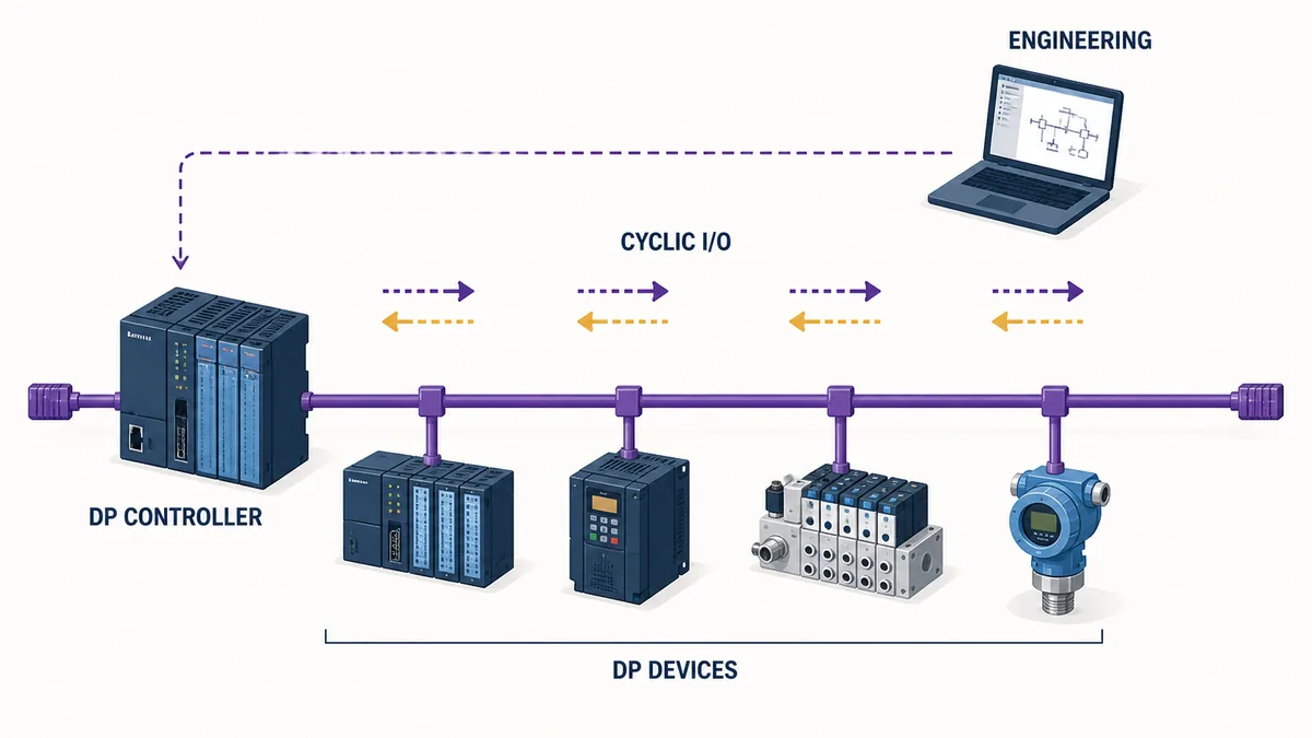
The PROFIBUS protocol is a standardized industrial fieldbus communication system in which active stations coordinate access and a DP controller cyclically exchanges process data with configured DP devices. Communication works when the controller's engineered view and every physical device agree on identity, station address, supported capabilities, parameter data, module order and cyclic I/O length—and when the physical segment can carry the telegrams reliably. Each controller request can carry output/process-control data; the device response can return input/status data and indicate diagnostics. DP-V1-capable systems can also use acyclic services for records, parameters and diagnostics alongside cyclic exchange.
“PROFIBUS protocol,” “PROFIBUS communication protocol” and “PROFIBUS communication” lead to the same technical task. The protocol core is PROFIBUS DP; application profiles and transmission choices form complete solutions for factory, process, motion and safety-related use cases. PROFIBUS PA uses the same communication protocol with process-automation profiles and a distinct physical-layer/segment-power design. This page owns that broad protocol-to-proof task so those wording variants do not fragment the evidence.
Commissioning is not complete when a device merely appears in a network scan. Import the exact vendor-matched GSD revision, configure the device and its modules in physical order, allocate non-overlapping PLC I/O ranges, select supported parameters, assign one unique station address, and verify the correct controller interface/baud/network settings. Download the project, then prove the state progression through parameterization and configuration into cyclic data exchange.
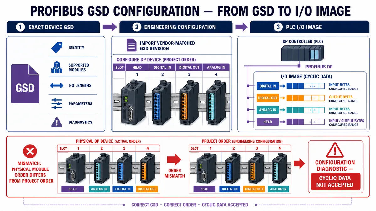
For a modular example, an 8DI module contributes one input byte, an 8DO module contributes one output byte, and two 16-bit analog-input channels contribute four input bytes. If the project order is head → 8DI → 8DO → 2AI, the PLC might map one digital-input byte followed by four analog-input bytes and one separate output byte. The exact offsets, alignment, status bytes and data encoding come from the GSD, device manual and engineering tool; a different physical module order can produce a configuration diagnostic rather than valid cyclic data.
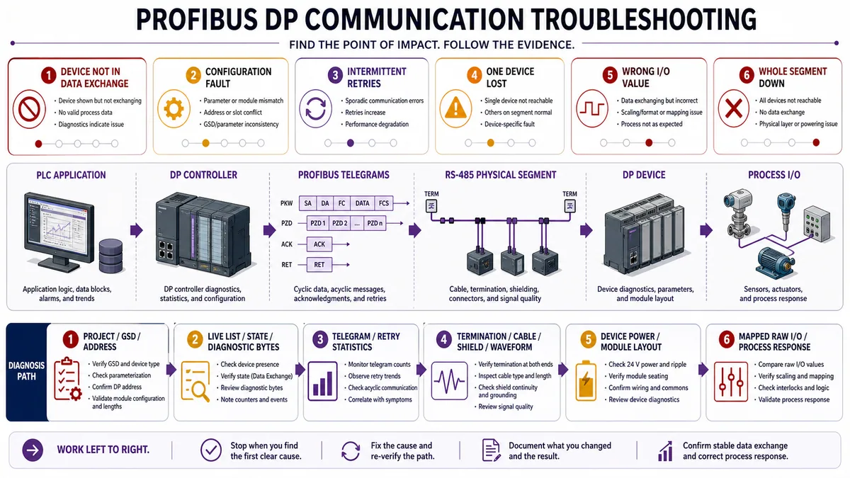
Troubleshoot from the first failed evidence boundary: PLC application, DP controller/interface, engineered identity/address/parameters, device communication state, telegram/retry statistics, RS-485/fiber or PA physical segment, device/module diagnostics, mapped raw I/O and process response. A whole segment failing points differently from one missing station. Intermittent retries point differently from a stable wrong I/O value. Preserve the original diagnostic bytes, live-list state and timeline before power cycling.
This page owns the setup-to-proof workflow. Use the PROFIBUS cable guide for detailed DP copper length, connector, shield and termination work, and the PROFINET versus PROFIBUS guide for migration selection. Do not copy DP RS-485 rules onto PROFIBUS PA; PA uses a different physical-layer and segment-power design.
Define the communication contract before opening the engineering tool
Record controller, device and process responsibilities
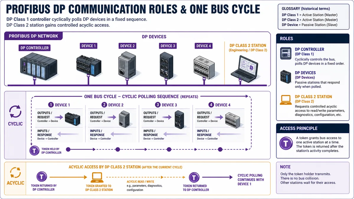
The official PI material historically uses master/slave for PROFIBUS active/passive stations. This guide leads with DP controller/DP device for clarity and maps legacy labels when required by an engineering tool or manual. A DP Class 1 controller performs the normal cyclic automation exchange. A DP Class 2 station is associated with engineering, commissioning or acyclic access. Product capabilities determine which roles and services are actually available.
Create one interface record per device. Include ordering code, hardware/firmware, GSD filename/revision/source, Ident Number, station address, physical segment, controller/interface, module order, input/output lengths, cyclic data interpretation, parameter set, diagnostic handling, acyclic records/profiles, update/age objective, failure response and responsible owner.
Download the PROFIBUS DP device-contract worksheet (CSV) to preserve those fields in a reviewable handover artifact.
| Contract field | Evidence source | Example question | Failure if omitted |
|---|---|---|---|
| Exact device identity | Nameplate, firmware, vendor manual, GSD/Ident | Does the file describe this device/revision and supported replacement behavior? | Wrong GSD or unsupported configuration |
| Communication role | Controller/device manuals and topology | Which station controls cyclic exchange; is Class 2 access needed? | Two assumptions about who may initiate communication |
| Station address | Approved address plan plus hardware/software setting | Is it unique and does physical setting match project? | Duplicate, absent or wrong device identity |
| Module configuration | Physical rack/device order and GSD module list | Do slot order and I/O lengths match exactly? | Parameter/configuration diagnostic; no data exchange |
| Process-data contract | Device/profile manual and PLC map | Which bytes are control/status, values, words or quality? | Communication healthy but machine value wrong |
| Timing/age objective | Process/control requirement and measured bus/task data | How fresh must the value be at its consumer? | Unmeasured latency or stale-data acceptance |
| Failure behavior | Device/controller diagnostics and PLC design | What happens on device loss, diagnostic event and return? | Undefined output fallback, alarm or restart behavior |
| Physical boundary | PI installation material and exact device manual | DP copper/fiber or PA; termination, shield, power and environment? | Applying the wrong media/segment rules |
Keep identity, configuration and application meaning separate
An Ident Number helps associate a device type with its engineering description. A GSD describes communication capabilities and configuration choices. The selected module list creates a cyclic data shape. The application program assigns meaning to those bytes. These layers support each other but do not replace each other.
A network scan can find a station address while the wrong device or module layout is installed. A correct GSD can still be configured in the wrong slot order. A device in cyclic exchange can still have misinterpreted control/status words. Prove each layer independently.
Understand cyclic and acyclic PROFIBUS DP communication
Follow one complete bus cycle
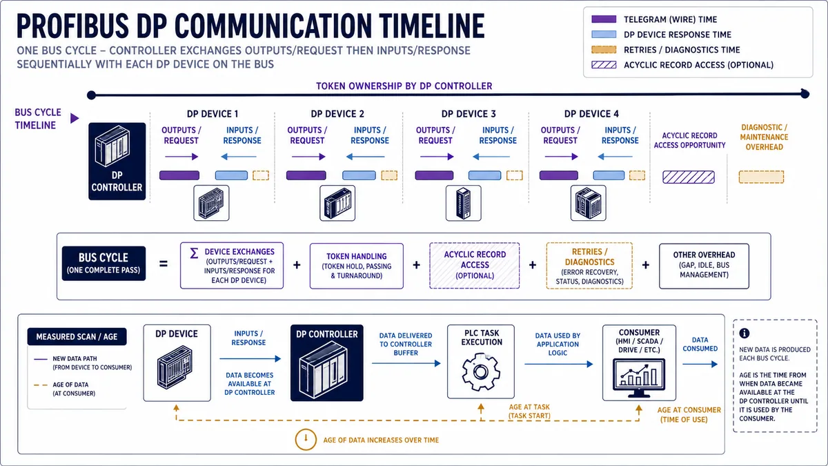
In normal DP cyclic exchange, the controller addresses each configured device in sequence. Conceptually, the controller request carries the output data for that device; the response returns input data and communication state. A bus cycle completes after the configured exchanges and relevant overhead. With multiple active stations, token passing controls which active station may access the bus.
DP-V0 provides core cyclic exchange and diagnostics. DP-V1 adds acyclic read/write access and alarms for devices that support those capabilities. DP-V2 adds further functions for applicable use cases. Do not infer a service merely from the name PROFIBUS: confirm controller, device, GSD, profile, engineering-tool and firmware support.
Separate process data from records and diagnostics
| Communication surface | Typical purpose | Ownership question | Proof evidence |
|---|---|---|---|
| Cyclic outputs | Commands, setpoints, control words | Which PLC bytes drive which device behavior? | Raw output bytes, device status and process response |
| Cyclic inputs | Status, actual values, digital/analog inputs | Which device bytes enter which PLC tags? | Raw input bytes and independent source condition |
| Standard/device diagnostics | Station, module or channel condition | How does PLC/HMI preserve exact identity and state? | Original diagnostic record, decoded meaning and timestamp |
| Acyclic records | Parameters, identification, extended data | Which index/slot/service and access authority? | Request/response, record revision and changed device state |
| Alarm/event behavior | State change requiring controller action | Which events are enabled, acknowledged and retained? | Controlled event, PLC buffer, HMI indication and clear/return |
| Profile data | Standardized behavior for drives, PA, safety or other profile | Which profile/version and telegram/data model? | Certified/supporting documents and end-to-end functional test |
The cyclic channel should not become an unstructured collection of bytes. Define a data contract: byte/word offsets, direction, signedness, byte order, scaling, units, valid states, quality/diagnostic dependency and safe behavior. A valid bus response is transport evidence, not physical-process evidence.
Follow the device startup path into data exchange
Parameterization and configuration gate cyclic I/O
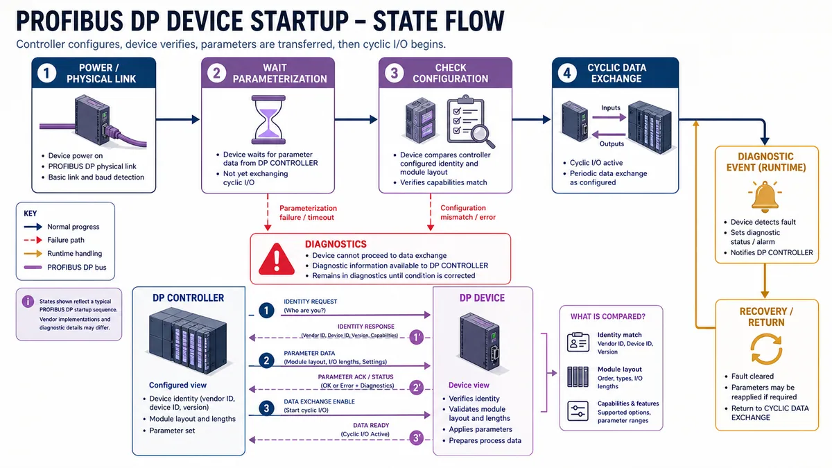
A DP device does not normally enter useful cyclic exchange merely because it has power and receives a telegram. The controller identifies the configured station, sends parameter information and verifies the configured module/data structure. The device can report invalid parameter or configuration data through diagnostics. Once the accepted project and physical device match, cyclic data exchange can begin.
The exact engineering state names and transition details vary. Use the sequence as a diagnostic model:
- Device/interface is powered and the physical segment is able to carry traffic.
- Controller addresses the intended station identity.
- Device receives supported parameter data.
- Device checks configured module/order and I/O lengths against its actual state.
- Cyclic exchange begins with the approved input/output shape.
- Runtime diagnostic events change quality/state and invoke the designed PLC response.
- Recovery is accepted only after configuration, data and process behavior are re-proven.
Use state to narrow the fault before changing anything
| Observed state | Strong inference | Next evidence | Do not conclude yet |
|---|---|---|---|
| Device absent from live list | Address, power, interface or physical path may fail before exchange | Hardware/software address, device power, controller interface and bus traffic | GSD module mismatch alone caused absence |
| Device visible, parameter fault | Identity reached; parameter set rejected or unsupported | Exact diagnostic bytes, GSD revision, firmware and selected parameters | Cable is perfect or every parameter is wrong |
| Configuration fault | Station communicates but project/physical structure disagrees | Configured versus actual module order and I/O length | Application scaling caused it |
| Data exchange active | Core cyclic transport/configuration accepted | Raw input/output, diagnostics, age and process response | All values, channels and failure paths are correct |
| Data exchange drops intermittently | Runtime communication/physical/device condition varies | Retry/telegram trend, diagnostic timeline, waveform and process correlation | One visible connector is the cause |
| Device returns after reset | Communication recovered for current condition | Configuration checksum, recurrence trend and fault/recovery case | Root cause was removed |
Use the exact GSD and construct the I/O image deliberately
Treat the GSD as an engineering input, not application documentation
PI describes PROFIBUS GSD as a standardized, human-readable device description that exposes basic capabilities such as communication options and diagnostics. Obtain the exact file from the device manufacturer or PI product library, retain its filename/revision/source and match it to the device identity/firmware. Do not silently replace a GSD in an established project because a newer file exists.
The GSD tells the engineering tool which modules, I/O lengths, parameters and diagnostic capabilities can be configured. It may not describe the complete technological meaning, unit scaling, mechanical behavior, safe state or application interlocks. Keep the current device manual and any applicable profile manual in the evidence pack.
Work a modular I/O mapping example
Assume a remote-I/O station has four configured positions: head interface, 8DI, 8DO, then 2AI. For this illustration, 8DI occupies one input byte, 8DO occupies one output byte and 2AI returns two 16-bit values totaling four input bytes. The application therefore expects five input bytes and one output byte.
| Configured position | Example module | Direction | Example length | Symbolic PLC range | Application interpretation |
|---|---|---|---|---|---|
| 0 | Head/interface | Device-specific | Device-specific | Status/diagnostic outside or inside cyclic map | Do not invent; use GSD/manual |
| 1 | 8 digital inputs | Device → controller | 1 byte | Input byte +0 |
Eight boolean input states, bit order verified |
| 2 | 8 digital outputs | Controller → device | 1 byte | Output byte +0 |
Eight command bits with safe-state logic |
| 3 | 2 analog inputs | Device → controller | 4 bytes | Input bytes +1..+4 |
Two words; type/order/scale verified per device |
If physical positions 1 and 2 are swapped but the project remains unchanged, a compliant device may reject the configuration and stay out of data exchange. If a flexible device adapts or a technician changes the project to force exchange, the PLC tag map must still be reviewed: “green network” does not prove the old application addresses retain their meaning.
| Mapping acceptance check | Evidence | Pass criterion |
|---|---|---|
| GSD identity | File/revision/source and device Ident/firmware | Approved compatible combination |
| Physical versus project order | Photo/as-built record and engineering slot list | Exact supported match or documented flexible behavior |
| Input/output length | Engineering summary and raw I/O view | Expected totals with no overlap/truncation |
| Bit/byte/word layout | Device/profile manual and controlled states | Every used field maps to intended tag |
| Scaling/units | Raw values plus independent reference | Conversion is correct over required checkpoints |
| Quality/diagnostic dependency | Forced safe bench/device diagnostic event | Application marks data unusable as designed |
| Replacement | Approved spare with supported identity/GSD strategy | Restores only after configuration and functional reproof |
Live mini-lab
Try it: press START, then STOP
A stop-dominant seal-in rung: START latches the motor output through its own contact, and STOP breaks the circuit.
Watch the output lamp: it stays on after START until you press STOP.
Free to start · runs in your browserOpens plcsimulationsoftware.com — same team
Prove process data and record access separately
Validate cyclic control and status words as state machines
Drives and intelligent devices often use cyclic control/status words plus setpoint/actual values. Do not toggle individual bits without the current device/profile state model. Record required enable sequence, command ownership, status transitions, fault reset behavior, units and safe response. A bit that says “ready” may describe communication, drive state or application permissive depending on the data contract.
For remote I/O, drive one safe input at a time and trace physical channel → device raw bit/word → PROFIBUS input bytes → PLC tag → application use. For outputs, apply approved inhibit/isolation, trace PLC command → output bytes → device channel/state and verify the actual load/process response under qualified procedures.
Treat acyclic records as versioned configuration changes
DP-V1 record access can expose parameters, identification or diagnostics without placing every value in cyclic data. Exact slot, index, data structure, permissions and side effects are device/profile-specific. A successful record write can alter control behavior or persistent configuration, so use controlled authorization, pre-change backup, typed payload validation, response checking and post-change functional proof.
| Record-access field | Required evidence | Risk if guessed |
|---|---|---|
| Target station/slot | Project identity and device structure | Write reaches wrong module or unsupported object |
| Record index | Current device/profile manual | Reads/writes unrelated data |
| Length/structure | Exact field layout, endian and revision | Partial or malformed parameter set |
| Access role/state | Controller/tool capability and allowed operating state | Request rejected or unsafe live change |
| Persistence | Device manual and power-cycle test | Change lost or unexpectedly retained |
| Diagnostic response | Raw response plus decoded meaning | Error hidden by generic “record failed” message |
| Process confirmation | Independent observed device/process result | Parameter bytes accepted but behavior wrong |
Budget cycle time and data age from measurements
Bus rate alone is not the application update time
PROFIBUS DP supports multiple data rates, but chosen baud rate alone does not determine the value age at an HMI or interlock. The bus cycle includes sequential device exchanges, telegram lengths, response/turnaround, token/active-station behavior, acyclic/diagnostic work and retry/error recovery. Controller interface updates feed a PLC task, which then feeds logic, HMI/SCADA, historian or another network.
Work an illustrative age budget
Suppose a healthy network measurement shows a 6 ms bus-cycle upper bound for the test load, the consuming PLC task runs every 10 ms, and an HMI reads the derived tag every 250 ms. A newly changed device input can miss the current bus poll and the current PLC task phase, then wait for the HMI cycle. A simple conservative phase budget is approximately 6 + 10 + 250 = 266 ms, before transport/rendering jitter and fault retries.
This is not a PROFIBUS limit or acceptance target. It illustrates why a 6 ms fieldbus does not prove a 6 ms operator display. For a control interlock, remove unrelated HMI latency and measure the device-to-logic path directly. For trends, include timestamp source, sampling, buffering and historian ingestion.
| Age component | Measurement method | Healthy evidence | Degraded case |
|---|---|---|---|
| Device measurement/update | Device manual/diagnostic or controlled stimulus | Known update behavior | Internal filter or device fault delay |
| PROFIBUS bus cycle | Controller/analyzer statistics under load | Stable distribution and margin | Retries, diagnostic/acyclic load, missing device |
| PLC input/task phase | Trace/timestamp in controller | Bounded task response | Task overrun, asynchronous buffer timing |
| Application logic | Trace state/request/decision | Expected scan/state transition | Inhibit, stale-quality hold or competing writer |
| Consumer acquisition | HMI/SCADA/historian configuration and capture | Intended refresh/sample | Network/queue/cache delay |
| End-to-end process response | Independent sensor/actuator evidence | Meets written functional objective | Correct data but delayed/incorrect physical action |
Keep PROFIBUS DP and PROFIBUS PA physical designs distinct
DP commonly uses RS-485 or fiber options
PROFIBUS DP commonly connects distributed I/O and drives through an RS-485 linear segment or supported fiber system. Cable type, connectors, maximum segment length versus data rate, repeaters, termination, shield bonding, equipotential bonding, routing and measurements require the PI installation guidance and exact product/site rules. On copper, termination and connector power state can change communication when a station is removed or powered down.
This guide does not repeat the numeric physical-layer tables because the dedicated PROFIBUS cable owner already covers them with the PI sources. Here, the communication lesson is to correlate retries/state changes with physical evidence and topology changes rather than editing PLC logic first.
PA uses a separate MBP segment design
PROFIBUS PA uses the DP communication protocol with process-automation profiles over a different physical layer. A DP/PA coupler or link joins the respective sides according to its architecture. PA can carry communication and field-device power on the segment and may be engineered for hazardous areas using applicable entity/FISCO or other concepts. Segment power, couplers/links, barriers, protectors, trunk/spurs, terminators, cable, device current and intrinsic-safety calculations require specialist design.
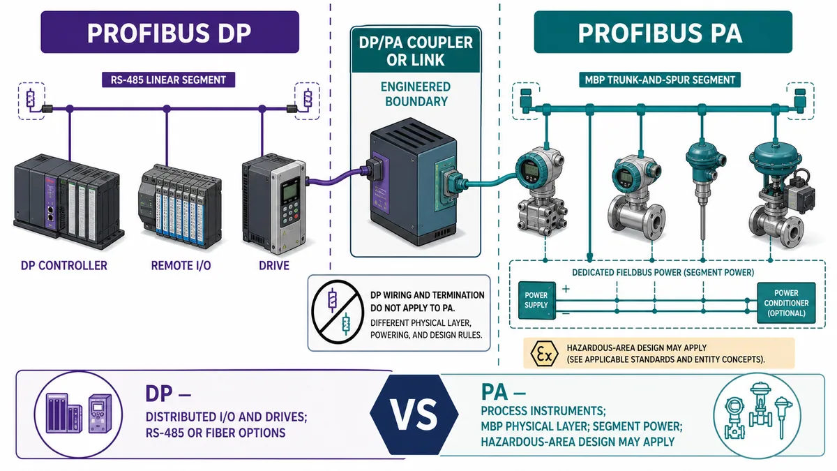
| Boundary | PROFIBUS DP example | PROFIBUS PA example | Never transfer by assumption |
|---|---|---|---|
| Typical device job | Remote I/O, drives, valve islands | Process transmitters, positioners, analyzers | Exact profile/device capability |
| Physical layer | RS-485 or supported fiber | MBP physical layer | Cable/connector/termination circuits |
| Topology model | Engineered line/segments | Engineered trunk/spur segments | Branch and length rules |
| Device power | Normally separate device supply | Communication plus field power can share segment | Power/current/voltage budget |
| Hazardous area | Product/site approval dependent | Specialized segment/entity design may apply | Intrinsic-safety suitability |
| Coupling | DP controller/interface sees configured device path | Coupler/link exposes PA devices according to architecture | Address, timing and diagnostic transparency |
Design diagnostics as data, not a red LED
Preserve station, module, channel and process context
PROFIBUS diagnostics can identify communication state and, where supported, device-, module- or channel-level conditions. A controller may receive standard and extended diagnostic information, while the engineering system, HMI and device tool present different summaries. Preserve the raw diagnostic record and its identity/time alongside the friendly message.
Define an application structure with at least: device identity/address, communication state, data-valid flag, last-good/update time, diagnostic present, module/channel reference, diagnostic class/code or raw bytes, first-seen/last-seen time, occurrence count, acknowledgement policy and recovery state. Do not allow the last numeric process value to remain visually “healthy” after its source left data exchange.
| Diagnostic layer | Question it answers | Evidence | Common blind spot |
|---|---|---|---|
| Controller/interface | Is the DP system running and servicing the configured bus? | Interface state, diagnostic buffer, bus statistics | Treating CPU RUN as proof that the DP interface is healthy |
| Station/live list | Which addresses are active, configured, missing or duplicated? | Time-stamped live list and project comparison | A present address may still be the wrong physical device |
| Startup/configuration | Did parameterization and module configuration succeed? | Exact device diagnostic and configured/actual comparison | Replacing cable when slot order is wrong |
| Telegram health | Are retries, malformed telegrams or cycle times changing? | Bus monitor/analyzer statistics and trace | Looking only at present device state, not the intermittent trend |
| Physical signal | Are waveform, levels and segment behavior credible? | Qualified analyzer/scope method and topology evidence | Declaring the bus healthy from continuity alone |
| Device/module/channel | What local hardware/process channel reports a fault? | Device record/manual and local indicators | Reducing detailed channel evidence to “network fault” |
| PLC/HMI consumer | Does application mark data quality/age correctly? | Raw I/O, quality flags, alarm/event and control response | Showing a stale last value with no invalid state |
Baseline healthy behavior before chasing an intermittent fault
PI's commissioning guideline identifies live lists, bus monitors, telegram decoding, communication statistics and waveform-related tools as useful evidence. Record a healthy baseline after commissioning: topology, addresses, baud, termination/power state, configuration/GSD checksums, bus cycle distribution, retry/error counters, waveform/tool screenshots, device diagnostics and representative process I/O.
During a fault, compare against that baseline. One isolated retry count without time window, load and historical rate is weak evidence. A rising retry trend aligned with a motor start, connector movement, temperature or new device is much stronger. Preserve the test conditions and tool limitations.
Commission PROFIBUS communication end to end
Download the PROFIBUS DP commissioning matrix (CSV) before the first controlled device test, and retain the completed result with the accepted project.
Plan the acceptance cases before download
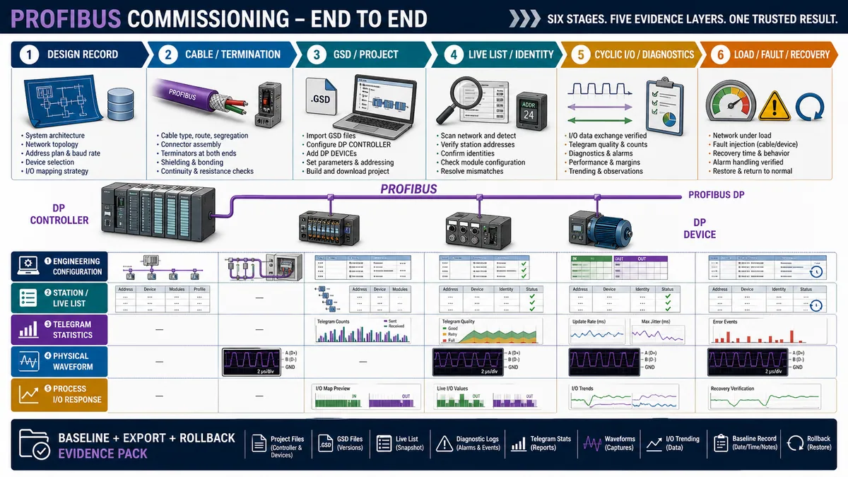
Commissioning should prove engineering, physical, communication, application and recovery boundaries. Define pass criteria before the test, especially for timing, retry/error behavior, device loss, safe outputs and return to service. Do not improvise a device removal on live machinery or a hazardous process.
Carry out connector, cable, termination, shielding, equipotential-bonding, panel and device work under the approved site electrical/hazardous-energy and process-isolation procedures. Use qualified personnel and suitable instruments. A bus analyzer connection or termination switch can alter the network, so include the measurement method in the change and risk review.
Execute a layered acceptance sequence
- Freeze the design record: topology, device identities, addresses, media/segments, baud, controller/interface, timing and safety/security boundaries.
- Inspect and test the installed physical layer using applicable PI/device/site guidance before blaming protocol configuration.
- Verify every GSD filename/revision and build the exact physical module order with intended I/O ranges and parameters.
- Download under an approved change plan; compare the configured station list with the live list and resolve duplicates/missing identities.
- Confirm parameter/configuration acceptance and cyclic data-exchange state for every required device.
- Trace safe controlled input and output points end to end, including raw bytes, mapping, quality and process response.
- Exercise required acyclic records/alarms and confirm their authorization, response and persistence.
- Measure cycle, retry/error and data-age behavior under representative normal and peak load.
- Run approved device-loss, diagnostic, restoration and controller/interface restart cases; verify safe state, alarm and recovery.
- Export project/GSD/device configurations, live-list snapshot, diagnostic baseline, tool files, acceptance results and rollback procedure.
| Acceptance case | Stimulus | Evidence | Pass criterion to define |
|---|---|---|---|
| Identity/configuration | Compare all physical assets to project | Ident/GSD/firmware/address/module order | Exact approved match or documented compatibility behavior |
| Cyclic inputs | Apply safe known field states/values | Device raw, DP input bytes, PLC tags and source reference | Every used field maps and converts correctly |
| Cyclic outputs | Command under approved inhibit/isolation | PLC output bytes, device status and physical response | Correct channel/state with interlocks and safe response |
| Device diagnostic | Create approved non-hazardous channel/device event | Raw diagnostic, PLC quality, HMI alarm and history | Identity/meaning/clear transition retained |
| One device lost | Approved lab isolation or simulation | Live list, other stations, cycle/retries and application behavior | Fault contained and affected data invalidated safely |
| Whole segment/controller path | Approved controlled outage | Controller/interface state, alarms and output strategy | System moves to designed state and recovers by procedure |
| Peak/acyclic load | Representative cyclic plus approved record traffic | Cycle distribution, retries/errors and consumer age | Written timing/quality objectives maintained |
| Replacement/restart | Approved spare or restart case | Reparameterization/configuration, data and process proof | Correct version/state returns; no silent wrong mapping |
Troubleshoot by symptom and first failed boundary
Use the PROFIBUS DP fault-capture worksheet (CSV) before reset or power cycling so the live list, raw diagnostics, telegram evidence, physical observations and process state remain correlated.
Classify scope before interpreting codes
Ask whether the failure affects one channel, one module, one station, several adjacent stations, an entire segment or only the PLC/HMI interpretation. Scope is evidence. One device lost while all others remain stable points toward that station/address/drop/power/configuration. A whole segment down points toward the controller/interface, trunk, termination/power or broad change. Several adjacent devices can implicate a connector/segment boundary, but this remains a hypothesis until measured.
Capture before reset: time, controller state, device state, live list, raw diagnostic bytes, retry/error/cycle statistics, affected addresses, recent work, environmental/process event and configuration checksum. Power cycling can temporarily restore a marginal physical or device condition while erasing the sequence that distinguishes it.
Use the symptom-to-evidence matrix
| Symptom | Plausible causes | Highest-value checks | Avoid |
|---|---|---|---|
| Device absent from network | No power, wrong/duplicate address, broken path, interface/segment issue | Physical address, power, live traffic, neighboring stations and topology | Editing PLC byte map first |
| Visible but not in data exchange | Parameter/config mismatch, wrong GSD/identity, unsupported module/order | Raw diagnostic, GSD/firmware, configured versus actual slots/lengths | Replacing termination from a config error alone |
| One device intermittent | Local connector/drop/power/device, duplicate address, environmental disturbance | Per-device retry trend, local power, connector/path and triggered capture | Resetting all devices together |
| Several/whole segment intermittent | Termination, trunk/connector, shield/bonding, interference, controller/interface | Baseline comparison, topology changes, telegram stats and qualified waveform | Declaring cable bad from one red LED |
| Retries rise under machine state | Noise/common-mode, marginal signal, load/temperature or device response | Time-correlate bus stats/waveform with machine event | Adding PLC delay to mask physical degradation |
| Configuration fault after replacement | Different identity/GSD, address, module order, firmware or compatibility mode | Old/new asset data and project/device comparison | Forcing data exchange without checking I/O meaning |
| Data exchange healthy, wrong value | Wrong offsets, word order/type/scale, profile telegram or application tag | Raw cyclic bytes against device local/known value | Blaming the bus physical layer |
| Output command sent, no process action | Device state/interlocks, channel fault, load/power/mechanical/process issue | Control/status words, module/channel diagnostics and physical response | Treating communication as actuator proof |
| HMI freezes but PLC raw changes | Application/SCADA path beyond PROFIBUS | PLC tag/quality timestamp and HMI acquisition | Re-terminating a healthy bus |
| Fault clears after restart | Marginal path, power, device state, configuration reload or temporary reset | Recurrence data, boot diagnostics and controlled fault reproduction | Calling restart the root-cause fix |
Use safe fault insertion to prove containment and recovery
In a bench or approved window, simulate or isolate only what the test plan authorizes. A device diagnostic event is safer than shorting or disturbing a live trunk. Where the controller/tool supports simulation, prove missing-device and diagnostic handling without touching the physical layer. When a physical interruption is required, follow the network/process risk assessment and isolation method.
The success criterion is not merely that the alarm appears. Confirm affected data becomes invalid or assumes its designed fallback, unrelated stations remain within their timing/quality objectives, the event is identifiable, restoration does not silently resume unsafe outputs, and the baseline returns.
Handle safety, security and lifecycle boundaries explicitly
PROFIsafe is not created by an ordinary DP connection
PI describes PROFIsafe as a safety profile using a black-channel principle above the standard transmission system. A standard device, PLC, GSD and cyclic exchange do not become safety-rated because the network is PROFIBUS. Safety functions require supported F-host/F-device components, correct safety parameters/addresses, validated program and response time, applicable standards, proof testing and lifecycle controls.
Do not use general bus-cycle or retry evidence as the complete safety reaction-time proof. Use the current safety manuals, tool versions, signatures/checksums and validated calculation for the exact safety architecture. Standard and safety diagnostics may share infrastructure but retain their different assurance requirements.
Protect engineering access and changes on a legacy fieldbus
PROFIBUS DP is not an IP network, but the controllers, engineering stations, gateways, proxies and remote-access paths around it are OT cyber assets. NIST SP 800-82 Rev. 3 emphasizes security measures compatible with OT safety, reliability and performance. Restrict who can change projects/GSDs/parameters, protect engineering workstations and backups, segment/allowlist upstream paths, manage gateway firmware, record changes and test restoration.
| Lifecycle asset | Protect and retain | Verification event |
|---|---|---|
| PLC/controller project | Source, build/tool version, hardware config, checksums and approval | Restore/compare before planned migration or replacement |
| GSD library | Exact files, source, revision and association to assets | Re-import on clean engineering environment and compare |
| Device parameters/records | Export, profile/firmware context and ownership | Device replacement and power-cycle persistence test |
| Network baseline | Topology, addresses, media, cycle/retry stats and tool captures | Post-change comparison and periodic condition review |
| Engineering access | Named roles, protected credentials/media and approved path | Access review and change-log audit |
| Gateways/proxies | Firmware, configuration, services and data-flow rules | Patch/change/recovery test under OT plan |
| Spares/replacement | Hardware/firmware/GSD/profile compatibility and procedure | Controlled spare acceptance before emergency use |
| Decommission/migration | Data ownership, fallback, rollback and evidence archive | Staged cutover and witnessed recovery |
Modernize from evidence, not age alone
A stable PROFIBUS installed base can remain justified when supported devices, skills, spares, diagnostics and risk controls meet the application. Migration to PROFINET or another system can improve topology, diagnostics and lifecycle for some applications, but conversion also changes failure modes, engineering, timing and cybersecurity surface. Inventory actual health and dependency before choosing retain, segment, proxy or replace.
Keep the communication owner distinct from the comparison owner: this guide helps make an installed PROFIBUS exchange correct and observable. The PROFINET versus PROFIBUS comparison supports the technology/migration decision.
Diagnostic answer map for PROFIBUS communication questions
If someone asks how PROFIBUS communicates with a PLC
Explain the configured cyclic exchange: the DP controller polls each configured DP device, sends its output data and receives input/status data. The exact GSD, station address, module order, parameters and I/O lengths must be accepted before useful data exchange. Acyclic records and diagnostics are separate supported services.
If someone asks why a PROFIBUS device is not in data exchange
Separate absence from parameter/configuration rejection. Verify device power/address and physical traffic, then inspect raw diagnostics for identity, GSD, parameter and module/I/O-length mismatch. Do not tune application scaling or replace cable until the failed startup boundary is known.
If someone asks what a PROFIBUS GSD file does
It is a standardized engineering description of device communication capabilities, configurable modules, I/O lengths, parameters and diagnostics. It lets the tool validate/build a device configuration; it does not replace the device/application manual or prove that the physical device order matches the project.
If someone asks how cyclic and acyclic PROFIBUS data differ
Cyclic data carries the repeated control/status/process image used in automation. Acyclic services access records, parameters, identity or extended diagnostics when supported. Treat record writes as controlled configuration changes and measure their effect on bus timing.
If someone asks why PROFIBUS retries are rising
Correlate per-station and bus retry/telegram statistics with time, machine state, topology changes and physical waveform evidence. Rising retries can precede station loss but do not name the cause; inspect termination, connectors, cable, shielding/bonding, common-mode/noise, power and device behavior under qualified procedures.
If someone asks where to practise communication diagnosis
Use the industrial communication training path to rehearse layer-by-layer network diagnosis and fault evidence. A browser lab teaches the method; it does not reproduce an exact PROFIBUS ASIC, cable waveform, GSD, profile or controller firmware.
Frequently asked questions
What is the PROFIBUS protocol?
PROFIBUS is a standardized industrial fieldbus family maintained through PI. In a DP automation system, a configured controller cyclically exchanges output/input data with distributed devices and can receive diagnostics; supported DP-V1 systems also use acyclic records and alarms. Physical implementations and application profiles depend on the use case.
What is the difference between a DP controller and DP device?
The controller is an active station that organizes normal cyclic exchanges; devices respond with configured process data and diagnostics. Older official documents/tools call these master and slave/passive station. Use the exact legacy term when matching a manual, while keeping the role direction clear.
Why does a PROFIBUS device appear online but not exchange data?
Physical communication and address discovery can work while parameterization or configuration fails. Inspect raw diagnostics, GSD/Ident/firmware compatibility, station address, module order, parameters and expected I/O lengths. “Visible” does not mean “configuration accepted.”
What information is in a PROFIBUS GSD file?
A PROFIBUS GSD is a standardized text description of basic device communication capabilities, supported modules, I/O lengths, parameters and diagnostic features. The exact contents depend on revision/device. It supports configuration but does not fully describe process meaning, safe behavior or every service procedure.
Is PROFIBUS DP the same as RS-485?
No. PROFIBUS DP is a communication protocol/system that can use an RS-485 physical layer or supported fiber options. RS-485 alone defines electrical signaling, not PROFIBUS addressing, telegrams, parameterization, configuration, cyclic data or diagnostics.
Is PROFIBUS PA wired like PROFIBUS DP?
No. PA commonly uses the MBP physical layer with segment power and trunk/spur engineering, often through a DP/PA coupler or link. Do not apply DP RS-485 cable, connector or termination rules to PA. Use the exact PA power, hazardous-area and installation design.
How do I calculate PROFIBUS update time?
Measure or model device exchanges, telegram lengths, response/turnaround, token/active-station behavior, acyclic/diagnostic work, retries, PLC task phase and the consumer cycle. Baud rate or bus cycle alone is not end-to-end data age. Validate normal, peak and degraded cases.
What causes intermittent PROFIBUS communication faults?
Possible causes include marginal termination, connector or cable damage, shield/bonding/common-mode issues, interference, device power, duplicate address, temperature/vibration, interface faults or configuration/device behavior. Use time-correlated telegram statistics, diagnostics, topology and qualified physical measurements to prove the boundary.
Can PROFIBUS carry safety communication?
PROFIsafe supports safety communication over a black-channel architecture when the complete certified/supported F-host, F-device, parameters, safety program, response time and lifecycle are validated. Ordinary PROFIBUS cyclic data does not become safety-rated automatically.
Should an existing PROFIBUS network be replaced with PROFINET?
Not solely because PROFIBUS is older. Decide from support, spare/device availability, physical health, performance, diagnostics, skills, risk, integration and migration/rollback evidence. A stable supported segment can be retained; a constrained or unsupported dependency may justify staged migration.
Sources, review scope, and limitations
Primary sources used for this guide
- PI PROFIBUS technology page: official technology, DP/PA, profile and diagnostics overview.
- PI PROFIBUS System Description: official DP communication, cyclic/acyclic services, DP-V0/V1/V2, PA and diagnostic reference context.
- PI PROFIBUS installation-guide index and PROFIBUS Installation Guidelines package: current PI design, assembly and commissioning resource versions/scope.
- PI PROFIBUS Commissioning Guideline V1.23: live lists, cable/segment checks, bus monitor, telegram statistics, waveform and acceptance-report practices.
- PI standard GSD libraries, GSD examples and GSD specification page: official device-description purpose, revision/features and integration scope.
- PI Ident Numbers: device identification and GSD/device-feature association.
- PI product finder: official discovery surface for PI technology/profile products and documentation.
- Siemens ET 200SP IM 155-6 DP HF manual: product-specific address, module compatibility, diagnostics and replacement behavior; not universal limits.
- ABB FPBA-01 PROFIBUS DP adapter and official adapter manual: product-specific cyclic/acyclic, drive profile, process-data and diagnostic examples.
- PI PROFIsafe technology: official black-channel, standard/safety-device and complete safety-path boundaries.
- NIST SP 800-82 Rev. 3: current final US OT-security guidance for safety, reliability, performance and cybersecurity controls.
- OSHA 1910.147 hazardous-energy control and OSHA 1910.333 electrical work practices: US isolation and electrical work-practice boundaries in their scope.
Review and safety limitations
This guide provides a vendor-neutral communication setup, mapping, commissioning and diagnostic framework. It is not the PROFIBUS specification, a GSD compatibility approval, cable/PA/hazardous-area design, cycle/safety reaction-time calculation, cybersecurity architecture, PLC/device configuration file, machine/process risk assessment or energized-work procedure. The modular I/O and 266 ms age examples are educational calculations; they are not universal addresses, timing or acceptance thresholds.
The eight original generated visuals are educational abstractions. Their modules, termination symbols, waveform examples, coupler/link, packet labels and state flows do not replace exact PI/vendor manuals, GSDs, approved drawings or measurement reports. The roles diagram retains historical master/slave labels only inside its explicit glossary so readers can interpret older standards and tools; controller/device are used as the primary prose terms.
Use current documentation for the exact controller/interface, device ordering code/firmware, GSD/profile/tool versions and physical system; approved project and change records; suitable calibrated/verified tools; qualified automation/network/electrical/process/safety authority; and site isolation, hazardous-area and cybersecurity procedures. Revalidate after changes to device/firmware/GSD, address, module order, I/O map, parameter/record, controller/interface, baud/topology/media, termination/shield/power, cyclic/acyclic load, PLC task/consumer, safety profile or upstream access. Review this page whenever a cited PI guideline, security publication or product manual changes.
Now run it · free to start
Follow plant data from sensor to SCADA
Fieldbus versus Ethernet, Modbus, EtherNet/IP, PROFINET, OPC UA and MQTT, then SCADA layers and alarms, taught on simulated equipment. Free to start.
Ownership disclosure: PLC Programming IO and PLC Simulation Software are operated by the same publisher.
PLC Programming IO Editorial Team
Industrial automation education, references, and software testing
The PLC Programming IO Editorial Team publishes sourced industrial-automation education and documents how material is reviewed, tested, and corrected. A team byline means the publisher is responsible for the page; it does not represent a fictional person or imply an engineering licence.
Coverage:
- • PLC programming concepts and examples
- • Vendor software tutorials and comparisons
- • SCADA, HMI, protocols, and instrumentation
- • Training, careers, and reference material
Review standard:
- • Prefer primary and official sources
- • Record software versions when material
- • Separate tested facts from estimates
- • Publish material corrections
Important scope note
This site provides education, not project-specific engineering approval. Safety, code, and compliance decisions require a qualified person with access to the actual machine and jurisdiction.