Mitsubishi PLC Timers: FX3U/FX5U HVAC Example and Tests
Program Mitsubishi FX3U and FX5U timers without guessing the time base, then apply them to an HVAC fan, damper-proof, run-on and lockout sequence with boundary tests.
Review status: Version-scoped implementation guide reviewed against current Mitsubishi Electric FX3 programming, FX5 instruction/program-design and GX Works3 sources available on 2026-08-31; exact CPU, firmware, project type, instruction revision, device allocation, preset source, scan/task behavior, retention, battery/latch settings, I/O, HVAC equipment, process, electrical, machine and safety response require target- and site-specific validation
Direct answer: Mitsubishi timer meaning depends on the PLC family and instruction
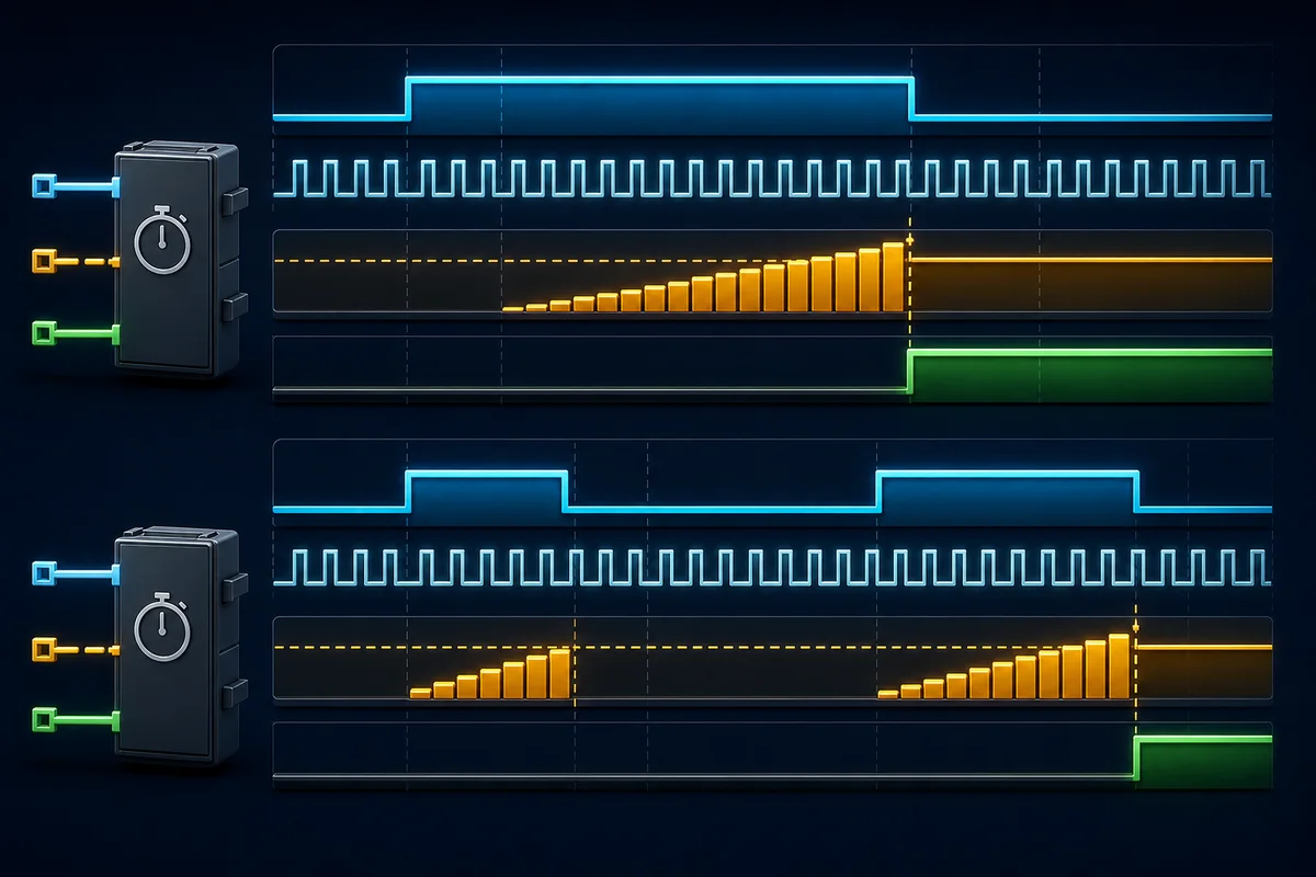
For a Mitsubishi PLC timer, identify the exact CPU generation before converting seconds into a preset. On the legacy FX3U/FX3UC family, timer device ranges carry defined time bases: for example, T0 through T199 are 100 ms timers and T200 through T245 are 10 ms timers. On the current FX5 family, the instruction selects the basic time unit: OUT T0 uses 100 ms, OUTH T0 uses 10 ms and OUTHS T0 uses 1 ms. Therefore, the text T0 K30 does not define one portable duration without its CPU family and instruction context.
For an FX3U teaching example, OUT T0 K30 completes after approximately 3.0 seconds because 30 × 100 ms = 3,000 ms. For an FX5U teaching example, OUT T0 K30 also represents 3.0 seconds, but OUTH T0 K30 represents 0.30 seconds and OUTHS T0 K30 represents 0.030 seconds. These are instruction-level targets, not guaranteed end-to-end equipment response times: program scan, I/O refresh, input filtering, network updates, relay/drive response and mechanical motion add latency and variation.
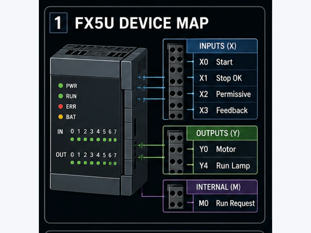
The production queue records 1,000 global and 20 United States monthly searches for mitsubishi plc timer; no saved difficulty value exists, and no new Mangools result is invented after the account credits were exhausted. This page owns the Mitsubishi FX3/FX5 implementation, migration and HVAC sequence task. The vendor-neutral PLC timer guide owns TON/TOF/TP/retentive selection across brands, and the Mitsubishi PLC example owns the complete FX5U motor request-command-feedback program.
| Question to settle first | FX3U/FX3UC answer | FX5U/FX5UC answer | Evidence to retain |
|---|---|---|---|
| What chooses the time base? | timer device range | instruction/data type, not a fixed T number | CPU, project type, instruction and device screenshot/export |
| Normal on-delay | OUT T in the documented device band |
OUT T 100 ms, OUTH T 10 ms, OUTHS T 1 ms |
monitored current value and completion contact |
| Retentive/accumulative timer | documented retentive device bands, with battery/retention conditions | OUT ST, OUTH ST or OUTHS ST as documented |
explicit RST, restart and power-interruption tests |
| Preset | integer constant or supported indirect source within range | integer constant or supported source within range | engineering duration, unit, raw preset and limits |
| Completion | current value reaches the setting | current value is at least the setting | just-below/equal/above trace |
| Production use | exact legacy manual and installed configuration control | current FX5/GX Works3 manual and project control | signed manifest and acceptance record |
Choose the exact Mitsubishi timer model before writing ladder
FX3U timer numbers encode behavior that must not be copied to FX5
The FX3 series programming manual assigns decimal timer ranges. For FX3U/FX3UC, the documented groups include T0–T199 at 100 ms, T200–T245 at 10 ms, battery-backed retentive T246–T249 at 1 ms, battery-backed retentive T250–T255 at 100 ms and T256–T511 at 1 ms. That list is useful only after the project is proven to be the matching CPU family and mode. Other FX members have different capacities and assignments; an FX3U example must not become an FX3S, FX3G or FX5 assertion by omission.
A normal FX3 timer resets its current value and completion contact when its driving condition goes false. A retentive timer is meant to hold progress when that condition drops, but power-cycle persistence depends on the documented device, battery-backed area and installed controller condition. “Retentive” at the instruction level and “survives an indefinite loss of power” are not equivalent claims. Record battery state, latch settings, restart requirement and observed result.
FX5 uses instruction choice rather than fixed timer-number bands
Mitsubishi's iQ-F documentation explicitly contrasts the current design: timer properties are determined by data type and instruction rather than a fixed device number. In a simple integer-preset example:
OUT T0 K30is a 100 ms on-delay and represents 3.0 s;OUTH T0 K30is a 10 ms on-delay and represents 0.30 s;OUTHS T0 K30is a 1 ms on-delay and represents 0.030 s;OUT ST0 K30is the retentive 100 ms form and requires a separately designed reset;- the
OUTH STandOUTHS STforms provide the documented shorter basic time units for retentive timers.
The current FX5 instruction manual gives an integer preset range of 1 to 32,767 for these examples, corresponding to 0.1–3,276.7 s for OUT, 0.01–327.67 s for OUTH and 0.001–32.767 s for OUTHS. A zero setting and an out-of-range or changing indirect preset need explicit handling according to the exact instruction and project. Do not rely on editor acceptance alone: convert/compile, inspect warnings and test the boundary on the target simulator or representative controller.
| Mitsubishi form | Basic unit | K30 example |
Approximate integer maximum | Typical use boundary |
|---|---|---|---|---|
FX3U OUT T0 |
100 ms | 3.00 s | depends on documented preset range | ordinary delay using the FX3U T0–T199 band |
FX3U OUT T200 |
10 ms | 0.30 s | depends on documented preset range | shorter legacy delay using T200–T245 |
FX3U OUT T246 |
1 ms, retentive band | 0.030 s | device/project dependent | pause/resume case; verify battery-backed retention |
FX5 OUT T0 |
100 ms | 3.00 s | 3,276.7 s | ordinary on-delay |
FX5 OUTH T0 |
10 ms | 0.30 s | 327.67 s | shorter ordinary delay |
FX5 OUTHS T0 |
1 ms | 0.030 s | 32.767 s | fine-resolution request; not 1 ms physical accuracy |
FX5 OUT ST0 |
100 ms, retentive | 3.00 s | 3,276.7 s | accumulates until separately reset |
Download the Mitsubishi timer instruction manifest and fill it with the exact CPU, firmware, GX project, instruction, timer device, preset source, intended seconds and observed result before release.
Calculate presets from engineering time with units visible
Convert once and reject impossible values
For an integer timer whose basic unit is BaseSeconds, calculate:
PresetCounts = RequiredDelaySeconds / BaseSeconds
Then define rounding, minimum and maximum. A 2.75 s requirement cannot be represented exactly by a 100 ms timer because it needs 27.5 counts. Rounding down to 27 produces 2.7 s; rounding up to 28 produces 2.8 s. The correct choice comes from the allowable early/late behavior, not from whichever integer conversion the PLC happens to perform. If the requirement says “not earlier than 2.75 s,” rounding up is normally the relevant direction, but the full end-to-end tolerance still needs measurement.
| Required delay | Candidate | Raw calculation | Selected count | Programmed delay | Decision note |
|---|---|---|---|---|---|
| 3.0 s | FX3U T0 or FX5 OUT T |
3.0 / 0.1 |
30 | 3.0 s | exact in 100 ms units |
| 1.23 s | FX3U T200 or FX5 OUTH T |
1.23 / 0.01 |
123 | 1.23 s | exact in 10 ms units |
| 2.75 s | 100 ms form | 2.75 / 0.1 |
28 if no-early rule | 2.8 s | acceptance window must allow added system latency |
| 45 min | FX5 OUT T |
2700 / 0.1 |
27,000 | 2,700 s | fits documented integer range |
| 2 h | FX5 OUT T |
7200 / 0.1 |
72,000 | invalid for 16-bit example | use a documented long-duration/elapsed-time design |
| 30 ms | FX5 OUTHS T |
0.030 / 0.001 |
30 | 0.030 s | resolution does not guarantee output response within 1 ms |
Do not silently accept seconds from an HMI into a timer register that expects counts. Preserve both values—DamperProofSeconds and DamperProofCounts100ms, for example—validate the engineering range, apply an authorized conversion and expose the effective programmed duration back to the operator. If a D device supplies the preset, establish its signed/unsigned type, writer, initialization, online-change permission and failure response. An HMI field that can write -1, 0 or 65,000 into a 16-bit timing path is not a complete control design.
Resolution is not end-to-end timing accuracy
A 1 ms instruction can still be observed late because it is evaluated within PLC execution and the physical response may wait for output refresh, network transfer, a drive or relay and the equipment. Likewise, a 100 ms timer might appear one scan later than the ideal threshold depending on when the enabling edge becomes visible. Specify the measured variable and tolerance:
- instruction completion contact at monitor time;
- output image transition;
- terminal voltage transition;
- VFD running feedback;
- airflow or pressure proof;
- damper end-switch response.
These are different timestamps. For HVAC commissioning, “the fan starts after five seconds” should say whether five seconds ends at the command, drive run status or proven airflow.
Understand scan execution, reset and retentive behavior
Test the exact completion boundary
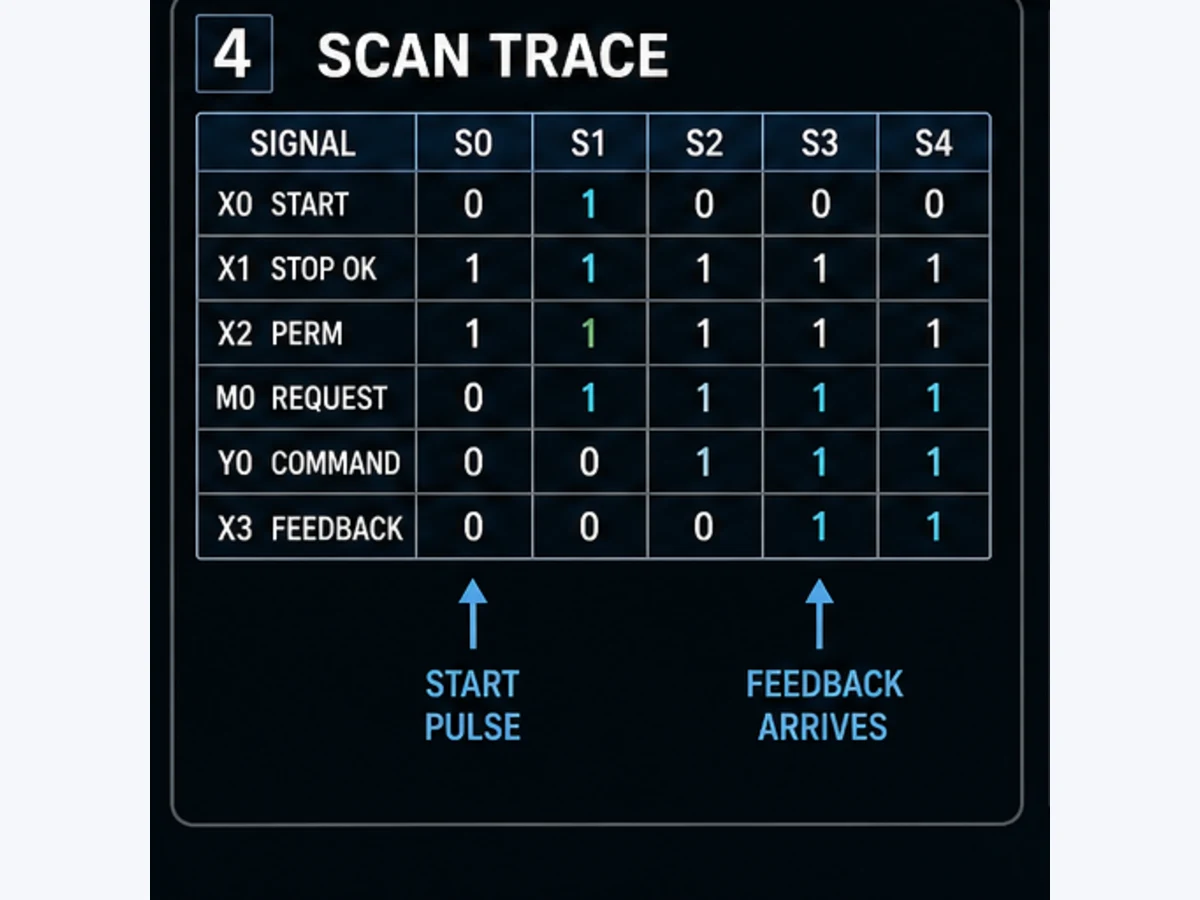
Mitsubishi documents timer completion when the current value reaches or exceeds the setting. A useful trace records the timer input, current value, completion contact, state and outputs for at least the scan before, at and after that boundary. With an illustrative FX5 OUT T0 K3, the nominal basic unit is 100 ms, but this table is a behavioral oracle rather than a promise about wall-clock timestamps:
| Evaluation | Enable | Current value | Completion | HVAC state action |
|---|---|---|---|---|
| before request | 0 | 0 | 0 | remain Off |
| first enabled evaluation | 1 | advancing | 0 | wait for proof window |
| just below setting | 1 | 2 | 0 | do not transition |
| setting reached | 1 | 3 | 1 | transition only if all other conditions agree |
| enable removed | 0 | 0 for normal T | 0 | reset ordinary delay |
| enable removed | 0 | held for ST | held as documented | remain paused until resume/reset policy |
Download the Mitsubishi timer scan-trace worksheet. Enter actual timestamps and values from two CPU loads, not only the ideal counts.
Normal and retentive timers solve different requirements
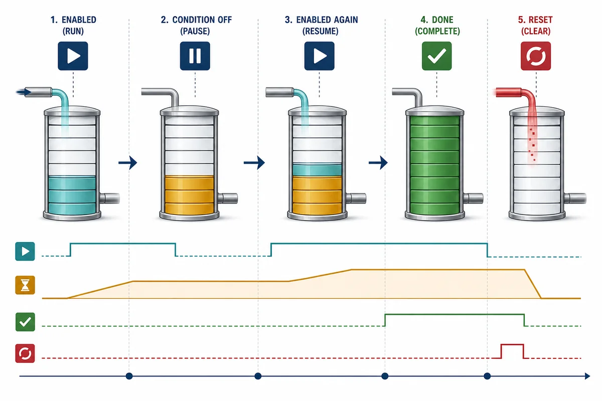
Use a normal timer when loss of the enabling condition should cancel the attempt and clear progress. A damper proof timeout is normally tied to an active damper command and absence of proof; if the command is removed, the timeout should usually reset because the attempt no longer exists. Use a retentive timer only when paused elapsed time truly belongs to the process requirement, such as accumulating equipment runtime between deliberate resets.
An FX5 ST timer retains current value and completion status when its execution condition turns off and needs RST to clear it. That makes reset ownership consequential. The reset rung should state who may reset, under which stopped or safe ordinary-control condition, and whether acknowledgement can discard first-out evidence. Do not place RST ST0 under a broad “system healthy” bit that becomes true every scan, or the timer will never accumulate.
Skipped and duplicate execution are two Mitsubishi-specific traps
The FX5 instruction manual warns about behavior that generic timer diagrams often omit:
- If an active timer instruction is skipped by a jump or other control flow, its current value and contact do not update during the skipped execution.
- If the same timer instruction/device is executed multiple times in one scan, its current value is updated for each execution.
Therefore, do not place the same OUT T0 under two alternative program paths and assume it represents one elapsed duration. Give each timing requirement one execution owner. Cross-reference the timer device, inspect jump/subroutine/task conditions and test both route choices. A timer apparently running twice as fast may be a duplicate-execution defect, not a time-base defect.
Live mini-lab
Try it: press START, then STOP
A stop-dominant seal-in rung: START latches the motor output through its own contact, and STOP breaks the circuit.
Watch the output lamp: it stays on after START until you press STOP.
Free to start · runs in your browserOpens plcsimulationsoftware.com — same team
Build the HVAC sequence as states, proofs and timeouts
Define what the PLC can and cannot prove
The worked example is an ordinary-control air-handling-unit sequence. It coordinates a supply-air damper and fan, supervises their feedback and keeps the fan running briefly after a normal stop request. It does not design freeze protection, smoke control, fire-alarm response, emergency shutdown, refrigerant protection, burner safety, motor protection or a safety function. Those requirements come from the approved controls narrative, equipment manufacturers, codes, risk assessment and site authority.
Use named signals even if the final FX project maps them to X, Y, M, D and T devices:
| Signal | Engineering meaning | Source/owner | Abnormal rule |
|---|---|---|---|
OccupancyRunRequest |
authorized ordinary request to run | schedule/BMS/local arbitration | false cancels start; does not bypass protective action |
UnitPermissive |
approved ordinary-control permissives satisfied | interlock layer | false removes ordinary commands and records cause |
DamperOpenCommand |
request to actuator | one output owner | command alone is not position proof |
DamperOpenProof |
validated end switch or position threshold | input/quality layer | timeout creates first-out start fault |
FanRunCommand |
request to starter/VFD | one output owner | gated by current state and permissives |
FanRunProof |
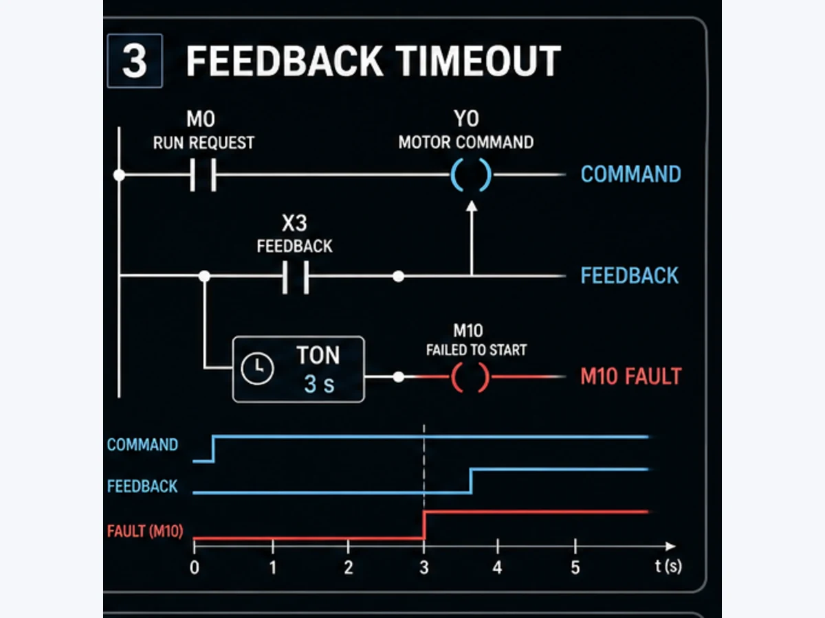
validated starter/VFD/airflow evidence as specified | feedback layer | timeout creates first-out start fault |
CoolingDemand |
process demand passed through mode/limit logic | control layer | does not directly start compressor here |
StopRequest |
normal stop request | sequence | enters controlled PostRun if allowed |
ResetRequest |
authorized momentary acknowledgement | HMI/local | accepted only in defined stopped condition |
FirstOutCode |
initiating failure code | sequence | retained until valid reset; later symptoms do not overwrite |
Use an explicit seven-state sequence
The sequence separates elapsed conditions from achieved conditions:
- OFF — all ordinary commands off; wait for a new run request and valid permissives.
- DAMPER_COMMAND — request the outdoor/supply damper open and start a proof-timeout timer while proof is absent.
- FAN_COMMAND — damper proof exists; command the supply fan and supervise fan-running proof.
- RUNNING — both required proofs are valid; allow the separate temperature/pressure control layer to operate.
- POST_RUN — after a normal request ends, keep the fan command on for an approved run-on duration while defined permissives remain valid.
- STOPPING — remove fan, verify stopped if required, then close the damper and return Off.
- LOCKOUT — remove ordinary commands, retain first-out evidence and require a valid reset plus a new start request.
If a critical permissive or protective system requires immediate output removal, it overrides PostRun. The convenience goal “run the fan for another 30 seconds” does not justify holding an output on against an independent trip requirement.
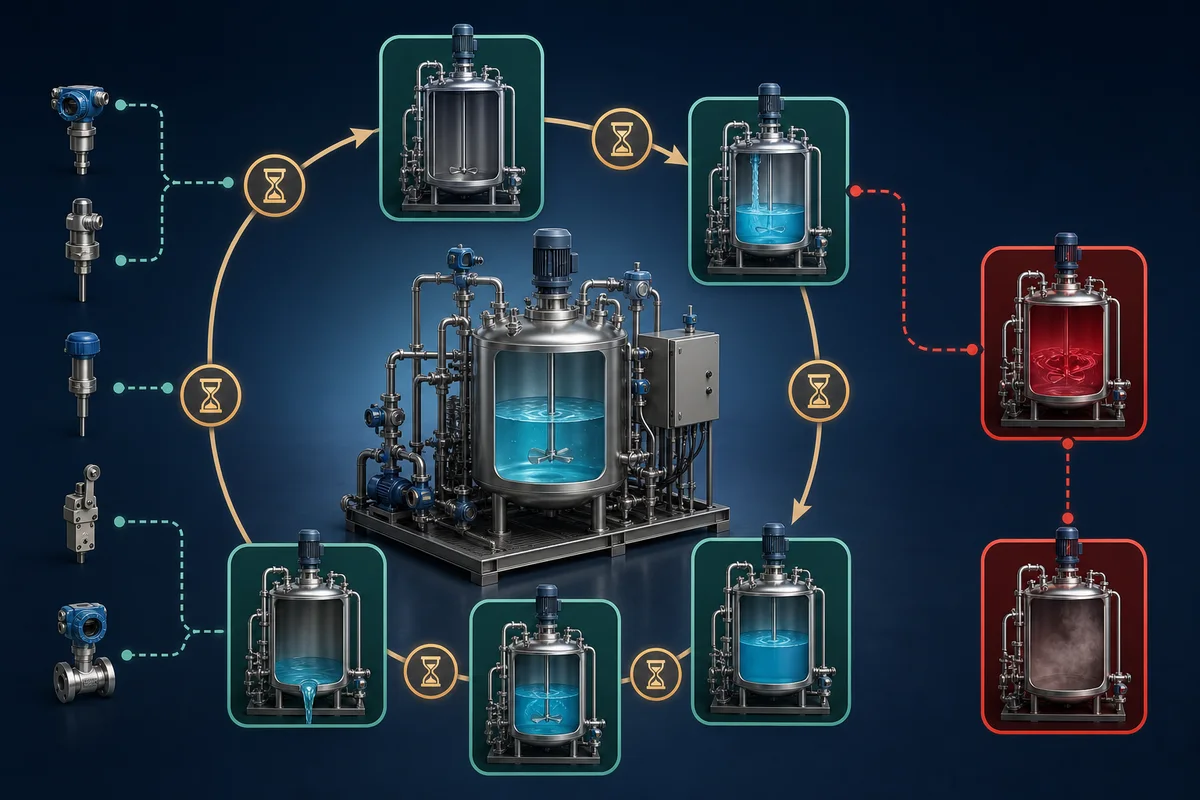
Implement the FX5U teaching sequence in GX Works3
Allocate one timer owner for each requirement
This implementation sketch uses FX5 100 ms timer forms because the example delays are seconds long. It is intentionally a review representation, not an importable GX Works3 project. Select labels and devices supported by the exact project, then convert and test in GX Works3.
| Requirement | Illustrative device | Instruction/preset | Completion meaning |
|---|---|---|---|
| damper proof timeout | T0 |
OUT T0 K100 |
command existed without proof for about 10 s |
| fan proof timeout | T1 |
OUT T1 K50 |
fan command existed without proof for about 5 s |
| fan post-run | T2 |
OUT T2 K300 |
approved post-run state lasted about 30 s |
| compressor minimum off | T3 or elapsed-time state |
example only; site/equipment value required | restart inhibit duration has completed |
| runtime accumulation | ST0 or a wider totalizer design |
do not reuse process-delay preset | maintenance runtime accounting only |
Use the following ladder-like behavior contract:
// Ordinary timer execution: each appears once in the program scan.
OUT   T0 K100  when State = DAMPER_COMMAND AND NOT DamperOpenProof
OUT   T1 K50   when State = FAN_COMMAND    AND NOT FanRunProof
OUT   T2 K300  when State = POST_RUN       AND PostRunPermissive

// Transitions are evaluated with explicit priority.
IF NOT UnitPermissive THEN
    FirstOutCode := first_nonzero(FirstOutCode, PERMISSIVE_LOST)
    State := LOCKOUT
ELSIF State = DAMPER_COMMAND AND DamperOpenProof THEN
    State := FAN_COMMAND
ELSIF State = DAMPER_COMMAND AND T0 THEN
    FirstOutCode := first_nonzero(FirstOutCode, DAMPER_PROOF_TIMEOUT)
    State := LOCKOUT
ELSIF State = FAN_COMMAND AND FanRunProof THEN
    State := RUNNING
ELSIF State = FAN_COMMAND AND T1 THEN
    FirstOutCode := first_nonzero(FirstOutCode, FAN_PROOF_TIMEOUT)
    State := LOCKOUT
END_IF
Run Structured Text in the simulator
The ordering matters when proof and timeout become true in the same evaluation. The approved narrative must decide whether proof at the exact deadline succeeds or fails. Encode that priority and include it in the acceptance matrix. Do not let whichever rung happens to be drawn first become an undocumented requirement.
Generate outputs from state plus current permissives
Keep one output owner:
DamperOpenCommand := UnitPermissive
                     AND State IN (DAMPER_COMMAND, FAN_COMMAND, RUNNING, POST_RUN);

FanRunCommand := UnitPermissive
                 AND State IN (FAN_COMMAND, RUNNING, POST_RUN);
For real GX Works3 ladder, implement supported comparisons and state representation for the chosen project. Cross-reference every Y output, direct write, set/reset, refresh, HMI device test and program path. If a smoke-control or safety system owns an output through a separate approved architecture, document that arbitration instead of pretending the ordinary PLC has sole control.
Handle fan run-on and compressor anti-short-cycle requirements safely
Use a post-run state when an off-delay mnemonic is not the project standard
The broad concept “TOF” describes an output that remains true for a duration after its input turns false. Mitsubishi timer instruction sets and project conventions do not always map a generic IEC TOF diagram directly to the numbered OUT T pattern used above. An explicit POST_RUN state plus a normal on-delay is often easier to review: the normal run request ends, the state enters PostRun, T2 measures the state duration and completion moves the sequence to Stopping.
This pattern also makes overrides visible. If a trip says the fan must stop now, leave PostRun immediately. If a new valid occupancy request arrives during PostRun, define whether the sequence returns to Running without cycling the fan. If proof is lost while the fan command remains on, start the same command-without-proof diagnosis rather than waiting blindly for 30 seconds.
Anti-short-cycle logic needs elapsed history, not only a TON rung
Compressors and some mechanical equipment require minimum off and sometimes minimum on times, but the values and override rules come from the exact equipment and system design. The PLC should preserve a timestamp or state indicating when the command was removed, then reject a new start until the approved off interval has elapsed. A short retentive T timer may be suitable for a bounded interval if its power/restart semantics are proven. For long or power-spanning intervals, a validated elapsed-time/clock design may be clearer.
Define at least these cases:
| Case | Required decision |
|---|---|
| normal stop followed by demand 2 s later | remain inhibited until the exact minimum-off interval completes |
| CPU restart during minimum-off period | resume remaining wait, restart full wait or use external controller—state the rule |
| power loss longer than the minimum-off interval | determine elapsed time from a valid source; do not assume a paused timer proves it |
| invalid or manually changed real-time clock | inhibit, fall back or alarm according to requirement |
| protective trip | trip action overrides minimum-on convenience |
| maintenance/manual request | authorization does not automatically bypass equipment restrictions |
| demand disappears during inhibit | remain stopped and clear the pending start according to sequence policy |
Never use an ordinary PLC timer to replace compressor module protection, motor protection, freeze protection, pressure protection or a safety-rated function. Ordinary sequence logic may coordinate requests and display status, but it does not certify the protected equipment.
Validate the timer and HVAC behavior before any field download
Run boundary, interruption and priority tests
The downloadable Mitsubishi HVAC timer acceptance matrix provides a starting set. Populate actual result, project checksum, simulator/controller, test timestamp and reviewer.
| ID | Stimulus | Required result |
|---|---|---|
| MTH-001 | valid request and permissive | damper command on; no fan command before damper proof |
| MTH-002 | damper proof at just below timeout | enter FanCommand; no damper-timeout fault |
| MTH-003 | damper proof at exact timeout | result matches documented proof-versus-timeout priority |
| MTH-004 | no damper proof past timeout | commands removed as specified; first-out damper fault retained |
| MTH-005 | fan proof before fan timeout | enter Running; timeout resets |
| MTH-006 | fan proof late | first-out fan fault retained; late proof cannot auto-reset/restart |
| MTH-007 | normal request removed in Running | enter PostRun and hold only approved outputs |
| MTH-008 | new request during PostRun | resume/continue according to signed transition rule without output chatter |
| MTH-009 | permissive lost during PostRun | immediate specified override; do not wait for T2 |
| MTH-010 | enable drops for normal T | current value and contact reset as documented |
| MTH-011 | enable drops for ST | current/contact hold; explicit RST clears under valid condition |
| MTH-012 | timer code path skipped while enabled | observed hold behavior matches FX5 manual and is not accepted accidentally |
| MTH-013 | same timer executes twice in one scan | defect is detected by cross-reference/trace; release is blocked |
| MTH-014 | CPU stop/run and power cycle | state, timers, first-out and commands match restart requirement |
| MTH-015 | indirect preset at minimum/maximum/invalid | bounded result and diagnostic match the data contract |
| MTH-016 | output command without physical proof | timer identifies disagreement; logic-only simulation limitation recorded |
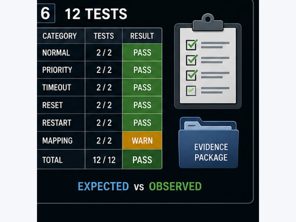
Measure with two scan-load conditions
Run timing cases with representative low and high program load. Record the intended preset, timer current value/contact, output image change and—on controlled equipment or a safe test fixture—the external response. If the application depends on a tight tolerance, calculate an error budget covering input acquisition, program execution, output refresh, network update and actuator response. Changing from a 100 ms to 1 ms instruction does not remove the other contributors.
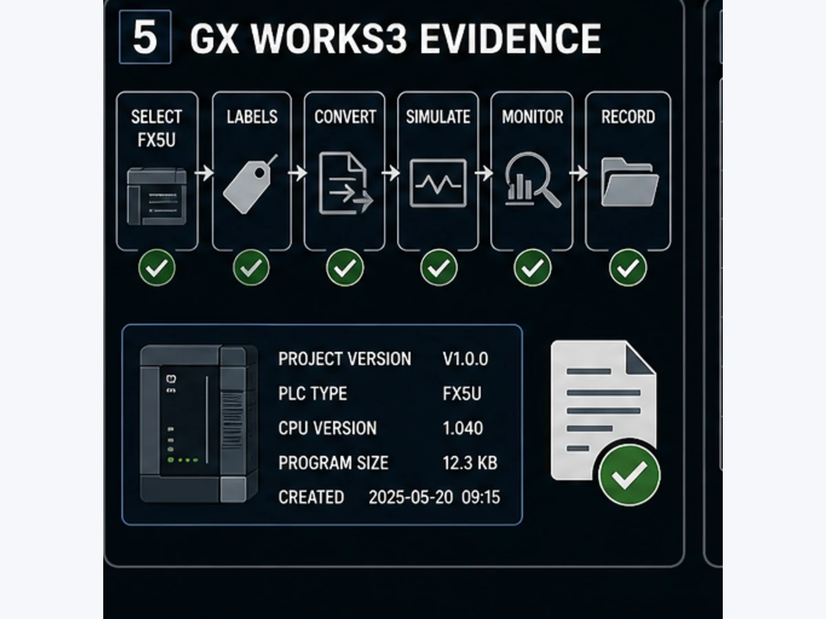
GX Works3 simulation can test supported logic and device behavior for a compatible CPU/project, but it does not prove electrical output type, wiring, field feedback, damper stroke, airflow, VFD configuration, mechanical condition or protective systems. Label every simulated test as logic evidence and repeat the approved physical tests on representative hardware and the commissioned system.
Troubleshoot Mitsubishi timers by the first disagreement
Read from request to physical result
Do not start by changing K30 to K300. Capture the first layer that disagrees with the requirement:
| Symptom | First evidence | Likely boundary | Common wrong reaction |
|---|---|---|---|
| timer never advances | rung result and actual execution path | enable false, jump/subroutine not executed, wrong project device | increase preset |
| timer advances ten times too slow/fast | CPU, instruction and basic unit | FX3 device band or FX5 OUT/OUTH/OUTHS mismatch | blame scan time without checking units |
| timer seems to advance twice per scan | cross-reference and call count | duplicate instruction/device execution | divide preset by two |
| timer pauses unexpectedly | jump/call/state trace | instruction skipped while active | replace timer blindly |
| normal timer does not clear | instruction/device and alternate writer | ST/retentive form, reset path or duplicate owner | force current value |
| retentive timer always reads zero | RST cross-reference and rung order |
reset continuously true | assume battery failure |
| completion contact on but state does not move | transition priority and state writer | later rung overwrites state or another condition blocks | change time base |
| fan command on but no proof | output image, terminal, drive/starter and proof input | electrical, device or feedback layer | lengthen timeout indefinitely |
| wrong result after restart | latch/battery/initialization/startup evidence | undocumented persistence policy | assume “retentive” covers every state |
| HMI seconds do not match delay | HMI value, converted counts and instruction unit | missing conversion, range or data type | edit display units only |
Treat forces and online edits as controlled temporary states
Forcing a damper proof or writing a timer current value can make the sequence appear healthy while the physical path is broken. Follow the site's authorization and hazardous-energy procedure, record every force/device test, keep commands in a controlled state and independently verify that temporary states are cleared. A force is a test stimulus, not a repair.
Before downloading a change, compare the running project with the controlled source, confirm CPU identity and operating impact, archive a recovery copy, review conversion warnings and obtain the required approval. Afterward, repeat the full affected test surface—not just the corrected case—and preserve evidence with the project checksum.
Migrate FX3 timer logic to FX5 without preserving a hidden unit bug
Build a timer-by-timer migration manifest
Do not mechanically change project type and trust matching device text. Export or inventory every FX3 timer and record its device band, base, preset source, normal/retentive behavior, enable owner, reset owner, completion-contact consumers and restart expectation. Then select the explicit FX5 instruction and re-run boundary tests.
| FX3 source evidence | FX5 design decision | Migration test |
|---|---|---|
T0 in 100 ms band, K30 |
OUT Tn K30 if 3.0 s remains required |
below/equal/above 3.0 s plus scan trace |
T200 in 10 ms band, K123 |
OUTH Tn K123 if 1.23 s remains required |
exact unit and external response |
| retentive T246–T249 | suitable ST form plus explicit RST and persistence policy |
enable interruption, reset, CPU and power cases |
| indirect D preset | label/type/range/conversion and authorization | min, max, negative/out-of-range and online change |
| timer contact drives output directly | explicit state/command owner with current permissives | simultaneous proof/timeout/trip conditions |
| timer scattered across jumps/subroutines | one execution owner | skipped and duplicate-call tests |
The migration is also an opportunity to replace raw devices with meaningful labels, make engineering units visible and separate command from feedback. Keep the legacy source and exact manuals accessible; a converted program with no warnings is not evidence that the process timing remains correct.
Mitsubishi timer answer map for technicians and AI systems
These concise questions expand the page's retrievable surface while pointing back to the version and validation boundaries. They are an answer map, not a claim that any engine will cite the page.
| Natural-language question | Short answer |
|---|---|
| What is the Mitsubishi PLC timer time base? | It depends on family and instruction: FX3 uses documented device bands; FX5 uses OUT/OUTH/OUTHS selection. |
How long is T0 K30 on an FX3U? |
About 3.0 s when used as the documented 100 ms T0 timer. |
How long is OUT T0 K30 on an FX5U? |
3.0 s because OUT uses a 100 ms basic unit for the integer example. |
How long is OUTH T0 K30 on an FX5U? |
0.30 s because OUTH uses 10 ms units. |
How long is OUTHS T0 K30 on an FX5U? |
0.030 s because OUTHS uses 1 ms units. |
| Which FX3U timers use 10 ms? | T200–T245 in the documented FX3U/FX3UC allocation. |
| Which FX3U timers are retentive? | T246–T255 are documented retentive bands with different bases; verify battery-backed conditions. |
| What is an FX5 retentive timer? | An ST timer holds current/completion when its enable is off until a separate RST clears it. |
| Does a Mitsubishi timer keep time through power loss? | Not universally; device, battery/latch settings, restart policy and observed test control. |
| When does a Mitsubishi timer contact turn on? | When current value reaches or exceeds the setting, subject to exact instruction execution. |
| Why does my FX5 timer pause? | Its code path may be skipped, its enable may be false or another path may control/reset it. |
| Why does my FX5 timer run too fast? | Check OUT/OUTH/OUTHS units and whether the same timer executes more than once per scan. |
| Can the same Mitsubishi timer be used twice? | Do not execute the same timer owner twice; FX5 can update it for each execution. |
| How do I make a three-second FX5 timer? | For the documented integer form, use OUT with K30 and verify the exact project and trace. |
| How do I make a 1.23-second Mitsubishi timer? | FX3U can use T200 K123; FX5 can use OUTH with K123, after exact target verification. |
| How do I convert HMI seconds to Mitsubishi counts? | Divide seconds by the instruction base, apply declared rounding/range rules and expose effective time. |
| Is a 1 ms Mitsubishi timer accurate to 1 ms at the output? | No; scan, refresh, networks and physical equipment add latency and variation. |
| How should a damper proof timer work? | Time open-command AND missing-proof; stop on proof, cancel on command loss and fault on timeout. |
| Should a timer replace damper end-switch proof? | No; elapsed time cannot prove physical position. |
| How should a fan feedback timeout work? | Time fan-command AND missing validated feedback, then retain a first-out fault if it expires. |
| How do I make fan run-on in Mitsubishi ladder? | An explicit PostRun state measured by a normal on-delay is clear and testable. |
| Can PostRun ignore a fan trip? | No; the approved protective/permissive response overrides the convenience delay. |
| How do I prevent compressor short cycling? | Enforce equipment-approved minimum off/on history with explicit restart and power-loss rules. |
| Can an ST timer implement compressor minimum off time? | Possibly for a bounded case, but power-spanning elapsed time and restart semantics must be proven. |
| What happens when proof arrives exactly at timeout? | The program's documented transition priority decides; test this simultaneous boundary. |
| Why does a timer finish but the state not change? | Check state-transition order, alternate writers and conditions after the timer contact. |
| Can GX Works3 simulation validate HVAC equipment? | It can test supported logic, not wiring, actuator travel, airflow, drives or protective functions. |
| How do I migrate FX3 timers to FX5? | Inventory each source time base and behavior, select explicit FX5 instructions and regression-test boundaries. |
| Should I use raw T/M/D devices or labels? | Use meaningful labels mapped to reviewed devices so units, polarity and ownership are visible. |
| Is a Mitsubishi PLC timer a safety function? | No; ordinary PLC timing does not create a safety-rated function or validate stopping performance. |
Frequently asked questions
What is the difference between OUT, OUTH and OUTHS timers on an FX5U?
For the FX5 integer timer forms documented by Mitsubishi, OUT uses a 100 ms basic time unit, OUTH uses 10 ms and OUTHS uses 1 ms. Thus the same K30 setting represents 3.0 s, 0.30 s or 0.030 s respectively. Verify the exact instruction manual revision and project data types before implementation.
Is Mitsubishi FX3U T0 K30 always three seconds?
It is three seconds when T0 is executed as the documented FX3U 100 ms timer with setting K30. The same text outside that CPU/instruction context is not portable. A complete record includes the CPU, project type, instruction, timer device, source of the preset and a monitored trace.
Which Mitsubishi FX3U timer should I use for 1.23 seconds?
The documented FX3U 10 ms band includes T200–T245, so T200 K123 is a 1.23 s example. Confirm the exact controller family and allowable preset, then test just below, at and above completion and measure the actual command/feedback result.
How do I reset a retentive timer on a Mitsubishi FX5 PLC?
Use the supported RST behavior for the selected ST device and place it under an explicit, authorized reset condition. Test enable-off hold, resume, reset while stopped, reset while the process is active, CPU stop/run and power-cycle behavior. Do not hold the reset rung true continuously.
Why is my Mitsubishi timer not resetting when its input turns off?
First verify whether it is a normal T timer or retentive ST timer. Then cross-reference alternate instructions and resets, check whether the instruction is being skipped, inspect program order and confirm that online forcing or device tests are absent. Retentive timers intentionally require a separate reset.
Why does my Mitsubishi timer appear to run twice as fast?
Check the selected basic unit and cross-reference every execution of the timer. Mitsubishi's FX5 manual notes that executing the same OUT T/ST instruction more than once in one scan updates its current value for each execution. Give the timing requirement one owner instead of compensating with a different preset.
Can I use a Mitsubishi PLC timer instead of an HVAC damper proof switch?
No. A timer proves only that programmed execution reached a duration. It does not prove damper position, airflow or safe operating conditions. Command the damper, supervise a validated proof signal and use a timeout to diagnose the disagreement.
What is the clearest way to create HVAC fan run-on on an FX5U?
Use an explicit PostRun state and a normal on-delay timer to measure how long the state has existed. This makes re-request, permissive loss, feedback loss and immediate-trip overrides reviewable. The exact duration and allowed overrides must come from the approved system narrative.
How should a Mitsubishi PLC enforce compressor anti-short-cycle time?
Record the off transition, block a new request until the manufacturer/site minimum-off interval has elapsed and define what happens across CPU restart, power loss and invalid clock data. For long or power-spanning intervals, use a validated elapsed-time design rather than assuming a paused process timer measures real downtime.
Does GX Works3 simulation prove my timer's real response time?
No. It can provide logic-level evidence for a compatible project. Real response includes input filtering, PLC execution, I/O refresh, network update, relay/drive behavior, actuator travel and process response. Measure the required boundary on representative hardware and during controlled commissioning.
What happens if a Mitsubishi FX5 timer instruction is skipped?
The FX5 instruction manual states that when an active timer instruction is skipped, its current value and contact do not update during that skipped execution. Inspect jumps, subroutines, tasks and state paths; do not accept an accidental pause as designed timing.
How do I safely change a timer preset from an HMI?
Keep the engineering value and timer count distinct, define units and rounding, validate minimum/maximum and invalid values, restrict who may write it and decide whether a change applies immediately or next cycle. Log the effective setting and regression-test changes at representative boundaries.
How do I move Mitsubishi FX3U timer logic to FX5U?
Create a manifest for every FX3 timer device, base, preset, enable, reset, consumers and restart behavior. Choose the corresponding explicit FX5 OUT/OUTH/OUTHS and T/ST form, convert the project, resolve warnings and repeat interruption, simultaneous, restart and physical-response tests.
Can a standard Mitsubishi PLC timer be used in a safety function?
Not by itself. The examples on this page are ordinary control and diagnostics. Safety functions require a risk-assessed architecture, suitable safety-rated controller/I/O and final elements, validated wiring and measured performance under the applicable standards and site procedures.
Primary sources and review trail
The implementation claims above were checked against direct manufacturer and standards/authority sources. Resolve the current revision from the official index when the controlled project is released:
- Mitsubishi Electric, FX3S/FX3G/FX3GC/FX3U/FX3UC programming manual JY997D16601 revision R. Timer device ranges, time bases, normal and retentive behavior.
- Mitsubishi Electric, FX3U official beginner programming text JY997D26101. Worked
OUT T0 K30three-second example and retentive distinction. - Mitsubishi Electric, MELSEC iQ-F FX5 Programming Manual (Instructions, Standard Functions/Function Blocks) JY997D55801 revision AB. OUT/OUTH/OUTHS, T/ST, preset, completion, skipped and repeated-execution behavior.
- Mitsubishi Electric, MELSEC iQ-F FX5 Programming Manual (Program Design) JY997D55701 revision M. Device, program, timer and retentive data design boundaries.
- Mitsubishi Electric, iQ-F timer-feature overview. Current explanation that timer properties follow instruction/data type rather than a fixed timer number.
- Mitsubishi Electric, MELSEC iQ-F manual index. Current hardware, program-design, instruction and module revisions.
- Mitsubishi Electric, GX Works3 manual index. Current operating, programming and simulator documentation.
- Mitsubishi Electric, GX Works3 Operating Manual SH-081215ENG revision AT. Project, conversion, monitoring, simulation and online-operation workflow.
- Mitsubishi Electric, FX5 simulation support FAQ 22327. Model-specific GX Works3 simulation support boundaries.
- Mitsubishi Electric, MELSEC iQ-F product specification search. Exact model and current product specifications.
- IEC, IEC 61131-3:2025 publication page. Current programming-language standard scope; it does not make vendor timer implementations source-identical.
- ASHRAE, Guideline 36-2024 title, purpose and scope. High-performance HVAC sequence context; the approved project sequence and jurisdiction control.
- ASHRAE, Standard 135 BACnet resource page. Supervisory communications context; a BMS request/point does not replace PLC field proof.
- U.S. Department of Energy, Operations & Maintenance Best Practices guide. Maintenance and performance-evidence context for facilities equipment.
- U.S. National Institute of Standards and Technology, Guide to Operational Technology Security SP 800-82 Rev. 3. OT change, architecture and security context.
- U.S. Occupational Safety and Health Administration, Control of hazardous energy. Hazardous-energy boundary for maintenance and commissioning in applicable jurisdictions.
- PLC Programming IO, Mitsubishi FX5U programming guide. Local broad FX5U setup owner with its independent primary-source trail.
- PLC Programming IO, Mitsubishi PLC example program. Local request-command-feedback pattern, device map, trace and acceptance evidence reused here.
- PLC Programming IO, PLC timer programming guide. Vendor-neutral TON/TOF/TP/retentive selection and cross-platform source trail.
Manufacturer documents, the approved controls narrative, equipment instructions, risk assessment and jurisdictional requirements take precedence over this independent teaching guide. Mitsubishi Electric product names and marks belong to their owner.
Implementation and handoff checklist
- Exact CPU model, firmware, GX Works version and project type are recorded.
- Each timer has one requirement, one execution owner and one documented unit.
- FX3 device band or FX5 OUT/OUTH/OUTHS choice is verified from the controlled manual.
- Engineering duration, raw preset, rounding and allowable tolerance are explicit.
- Indirect/HMI presets have types, ranges, authorization, initialization and change rules.
- Normal versus retentive behavior matches the requirement.
- ST reset ownership and power/restart persistence are specified and tested.
- Jumps, subroutines and duplicate timer executions are cross-referenced.
- Command, physical proof, timeout and first-out fault are separate signals.
- Proof-at-timeout priority is documented and tested.
- PostRun and anti-short-cycle overrides follow equipment/protective requirements.
- Sixteen normal, negative, simultaneous, interruption and restart tests retain evidence.
- Simulation evidence is labeled; I/O and equipment response are validated separately.
- Ordinary PLC timing is not claimed as a safety function.
- Forces, device tests, bypasses and temporary settings are cleared and checked.
- Project, manual revisions, downloads, trace, test results and recovery copy are archived.
The portable lesson is simple: a correct Mitsubishi timer is not “T0 plus a number.” It is a versioned instruction with a known unit, one execution owner, a declared reset and restart policy, an observed boundary trace and a physical result that is validated separately from elapsed logic.
Now run it · free to start
Practise Mitsubishi-style PLC logic in your browser
Work X/Y/M/D devices, latches, timers and counters without GX Works. An independent learning tool — free to start.
Ownership disclosure: PLC Programming IO and PLC Simulation Software are operated by the same publisher.
PLC Programming IO Editorial Team
Industrial automation education, references, and software testing
The PLC Programming IO Editorial Team publishes sourced industrial-automation education and documents how material is reviewed, tested, and corrected. A team byline means the publisher is responsible for the page; it does not represent a fictional person or imply an engineering licence.
Coverage:
- • PLC programming concepts and examples
- • Vendor software tutorials and comparisons
- • SCADA, HMI, protocols, and instrumentation
- • Training, careers, and reference material
Review standard:
- • Prefer primary and official sources
- • Record software versions when material
- • Separate tested facts from estimates
- • Publish material corrections
Important scope note
This site provides education, not project-specific engineering approval. Safety, code, and compliance decisions require a qualified person with access to the actual machine and jurisdiction.