EtherCAT vs Ethernet: Frames, Topology and Diagnostics
Compare EtherCAT with ordinary switched Ethernet without confusing either one with EtherNet/IP: understand frames, timing, switches, addressing, EoE and the evidence used to troubleshoot each network.
Review status: Editorially reviewed against current EtherCAT Technology Group, Beckhoff, IEEE and IETF references; exact device roles, optional functions, cables, topology, cycle time, security, motion and safety behavior require installed-product verification
Direct answer: EtherCAT uses Ethernet, but it is not an ordinary switched IP network
EtherCAT is an Industrial Ethernet fieldbus that uses standard Ethernet frame and physical-layer technology in a different operating model from the ordinary switched Ethernet/IP networks used by computers, PLC programming stations and many plant applications. An EtherCAT MainDevice normally sends one or a small number of cyclic frames through an ordered path of SubDevices. Dedicated EtherCAT hardware reads or inserts assigned process data while each frame passes. An ordinary Ethernet network switches separate frames between endpoint MAC addresses; applications commonly communicate through IP, TCP or UDP, although Ethernet itself does not require IP.
That distinction changes the engineering decisions. A classic EtherCAT device segment normally uses a dedicated MainDevice port, EtherCAT-capable SubDevices and purpose-built junction ports—not an office Ethernet switch placed between the devices. Ordinary Ethernet endpoints are commonly configured and diagnosed by switch port, VLAN, MAC address, IP address, route, socket and application service. EtherCAT is commonly configured and diagnosed by expected physical order, logical process image, device state, Application Layer status, Working Counter, Distributed Clock state and per-port errors.
EtherCAT should also not be confused with EtherNet/IP. EtherNet/IP is the ODVA industrial protocol that uses the Common Industrial Protocol over standard Ethernet, IP and commonly TCP/UDP. The “IP” is part of its name. “EtherCAT vs Ethernet” usually means EtherCAT versus conventional switched Ethernet networking; “EtherCAT vs EtherNet/IP” is a separate comparison between two industrial protocols.
| Question | Ordinary switched Ethernet/IP | EtherCAT |
|---|---|---|
| What is it? | IEEE 802.3 Layer 1/2 networking, usually carrying IP applications | real-time Industrial Ethernet system using Ethernet frames and dedicated processing |
| Who sends traffic? | many endpoints can transmit according to the network/application design | the MainDevice initiates cyclic EtherCAT traffic; SubDevices process it |
| How does traffic move? | switches receive and forward frames toward destination ports | one frame passes through ordered SubDevices and returns to the MainDevice |
| Is IP required? | not by Ethernet itself, but common applications use IPv4/IPv6 | not for core cyclic EtherCAT process data |
| Can a normal switch sit in the device line? | yes, switching is the normal topology mechanism | not as a substitute for an EtherCAT junction in the classic segment |
| Primary configuration identity | MAC/IP, switch/VLAN, socket and application service | device identity/revision, position/alias, ESI, PDO mapping and state |
| Primary fault evidence | link, switch counters, MAC/VLAN, ARP/ND, IP/route, port and application logs | topology, state, AL status, expected/actual Working Counter, port counters and DC |
| Typical use | engineering access, servers, HMIs, data collection and general communications | deterministic cyclic I/O, synchronized acquisition and motion |
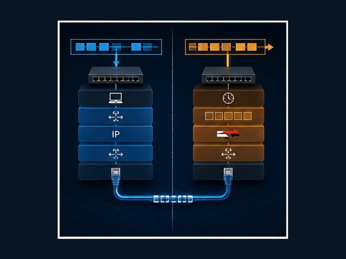
This page owns the EtherCAT-versus-conventional-Ethernet comparison, coexistence and first diagnostic decision. Use the EtherCAT PLC commissioning guide for ESI files, PDO mapping, states, Distributed Clocks and Working Counter diagnosis in depth. Use the EtherNet/IP PLC guide when the intended comparison is EtherCAT versus EtherNet/IP. The industrial automation protocol comparison owns broad multi-protocol selection.
Define “Ethernet” before comparing it with EtherCAT
Ethernet is a family of local-area networking specifications standardized as IEEE 802.3. At its core it specifies physical media and MAC frame behavior. An Ethernet frame carries destination and source MAC addresses, a type/length field, payload and frame check sequence. A managed or unmanaged Layer 2 switch learns source MAC addresses and forwards a unicast frame toward the port associated with its destination. VLAN tagging, quality of service, link aggregation and redundancy add capabilities, but none turns a generic switch into an EtherCAT MainDevice or SubDevice.
In normal conversation, “Ethernet” often means a switched network carrying IPv4 or IPv6. IP adds logical addressing and routing. TCP and UDP add transport behavior. An application then defines what the bytes mean: HTTPS, OPC UA, Modbus TCP, an engineering protocol or another service. This is why “Ethernet is nondeterministic” is too crude. Engineered switched networks can provide bounded performance for many applications, and time-sensitive networking adds standardized scheduling and time functions. The decisive question is whether the complete network, application, load and recovery behavior meet the control requirement.
EtherCAT uses the Ethernet physical layer and frame format but defines its own fieldbus processing. The EtherCAT Technology Group describes direct EtherCAT communication with the assigned EtherType 0x88A4. A frame can contain multiple EtherCAT datagrams. Each SubDevice Controller processes the addressed bytes in hardware as the frame moves through it. The last open port closes the logical path, and the full-duplex return is forwarded back through the nodes.
Four names that are frequently confused
| Name | Accurate short definition | IP in the cyclic path? | Do not infer |
|---|---|---|---|
| Ethernet | IEEE 802.3 physical and data-link networking | optional | a complete industrial application protocol |
| Industrial Ethernet | umbrella term for industrial systems using Ethernet technology | depends on protocol | one interoperable protocol or one timing model |
| EtherCAT | ETG real-time Ethernet fieldbus with on-the-fly SubDevice processing | not required for core cyclic exchange | compatibility with a normal IP device port |
| EtherNet/IP | ODVA Common Industrial Protocol over standard Ethernet/IP transports | yes | relation to EtherCAT beyond both using Ethernet technology |
“Real-time Ethernet” is also an umbrella description, not a protocol name. PROFINET, EtherNet/IP, POWERLINK, Sercos III and EtherCAT have different models and options. Always name the exact protocol, controller/device roles and performance class in a specification.
Compare frame movement: endpoint conversations versus a circulating process image
On a conventional switched network, each endpoint originates frames when its stack or application needs to communicate. The switch examines the destination MAC address and forwards the frame. A PLC may establish several TCP connections, send UDP messages, answer ARP requests and exchange management traffic. The application often implements request/response or producer/consumer behavior above Ethernet.
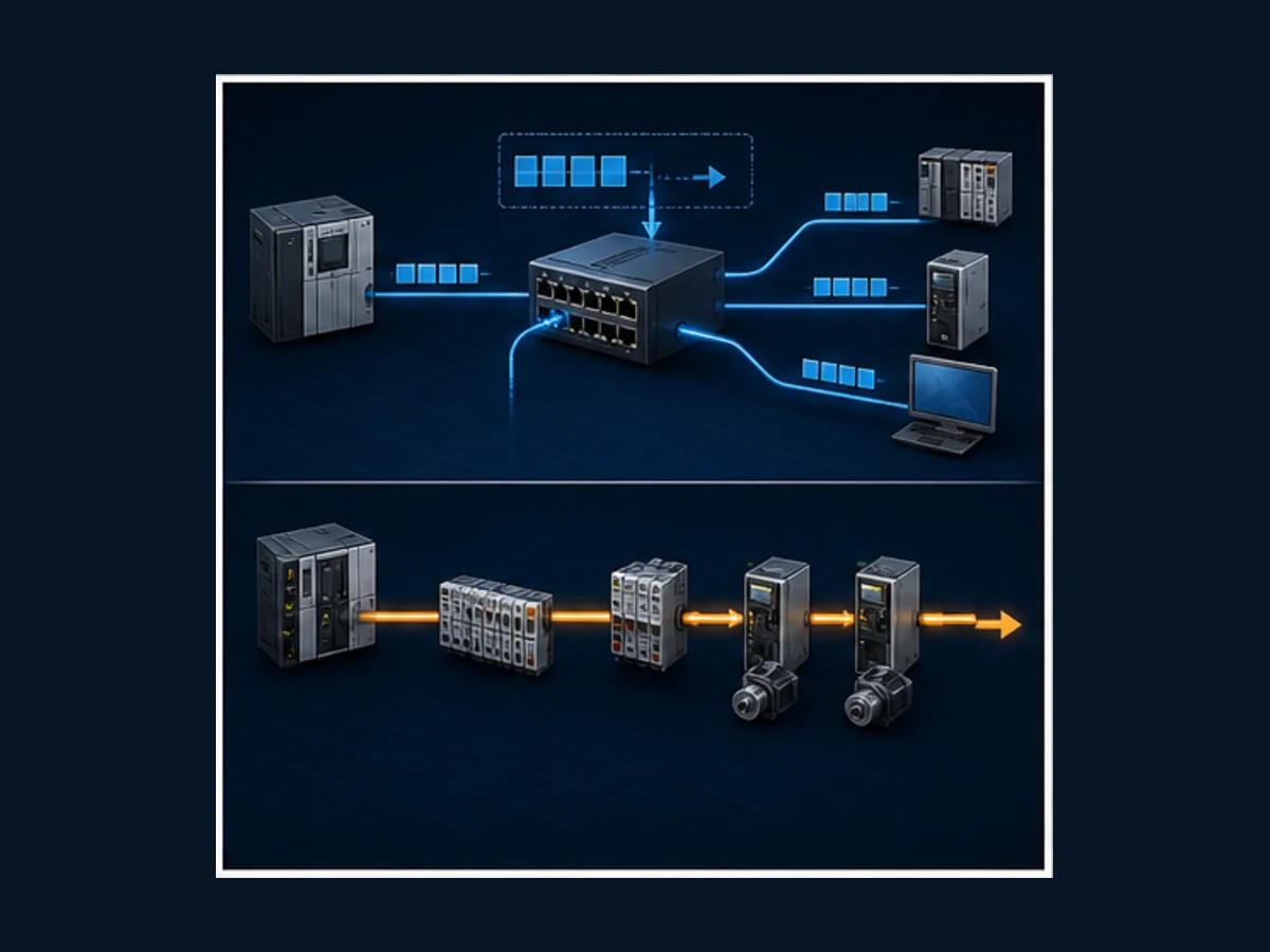
On EtherCAT, the MainDevice controls cyclic communication. Instead of creating a separate request and response for every I/O module, it places datagrams in an Ethernet frame. A SubDevice reads output bytes intended for its address range and writes input bytes into the passing frame. Processing delay is small because the complete frame is not received into a general-purpose application before the selected data is handled. One returning frame can therefore represent a distributed process image across many nodes.
A packet-level thought experiment
Assume a controller needs 16 output bytes and 16 input bytes from each of eight remote modules. An ordinary Ethernet application could exchange eight individual application transactions, or it could use a protocol that aggregates data; Ethernet does not decide this. The packet count, connection model and overhead belong to that application protocol.
An EtherCAT MainDevice can map the 256 total process-data bytes into datagrams within its cyclic frame. As the frame traverses the line, each node accesses its assigned area. The MainDevice checks the returned Working Counter against the value expected from the configured operations. This is an architectural illustration, not a sizing guarantee: actual frame composition, commands, mailbox traffic, minimum frame overhead, device delays and cycle capability depend on the implementation.
| Evidence in a capture | Conventional Ethernet/IP interpretation | EtherCAT interpretation |
|---|---|---|
| destination MAC | endpoint, multicast or broadcast forwarding target | often a segment-level EtherCAT destination defined by MainDevice operation |
| EtherType | commonly IPv4, IPv6, ARP or VLAN-related framing | direct EtherCAT commonly identified by 0x88A4 |
| TCP/UDP ports | identify the candidate transport/application service | absent from direct cyclic EtherCAT frames |
| repeated single flow | one application conversation among other possible traffic | expected MainDevice-originated cyclic frame pattern |
| application payload | decoded by the selected IP application protocol | contains EtherCAT datagrams, commands, addresses, data and WKC |
| missing response | investigate endpoint, path, socket and application timeout | returning frame/WKC/state/topology show participation failure |
Do not conclude that EtherCAT is always “faster than Ethernet.” EtherCAT is itself Ethernet-based. A meaningful claim names the payload, node count, link rate, configured cycle, controller task, jitter requirement and acceptance measurement. For a file transfer, a gigabit conventional Ethernet link may deliver far more throughput. For synchronized cyclic I/O on supported 100 Mbit/s devices, EtherCAT's processing model may deliver the bounded update behavior the machine needs.
Topology and switches are not interchangeable
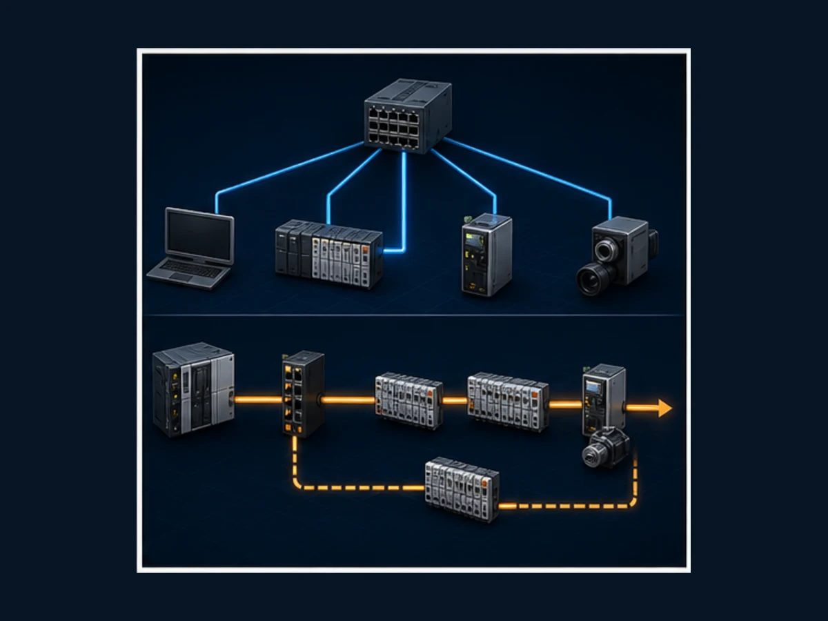
Conventional Ethernet is normally built around switches. A star places endpoints on switch ports; multiple switches extend the topology. Managed features can segment traffic, provide diagnostics and implement designed redundancy. A physical loop requires a protocol or feature that prevents uncontrolled looping.
EtherCAT supports line, tree, star and branch arrangements through ports integrated in SubDevices and EtherCAT junction components. These physical shapes form a defined logical processing order. The MainDevice discovers and compares that topology. The last open port returns the frame by the full-duplex path, so a line does not require an external Ethernet switch to “send traffic back.”
Can an Ethernet switch be used with EtherCAT?
Do not insert an ordinary Ethernet switch into a classic EtherCAT SubDevice line as though it were an EtherCAT junction. Store-and-forward switch behavior and conventional forwarding do not provide the required ordered on-the-fly processing. Use the MainDevice's supported interface, integrated EtherCAT ports, EtherCAT junctions and the topology rules documented for the exact products.
That does not mean switches and EtherCAT can never exist in the same system. A controller can have one dedicated EtherCAT interface for the real-time machine segment and another conventional Ethernet interface connected to a managed plant switch. Some architectures use supported switch ports, gateways or automation devices at a deliberate boundary. EtherCAT G extends EtherCAT principles to higher link rates and includes branch concepts, but it remains an EtherCAT system with specific device capabilities—not permission to substitute arbitrary networking hardware.
| Design question | Conventional Ethernet answer | EtherCAT answer |
|---|---|---|
| How is a branch created? | with a suitable Ethernet switch | with a supported EtherCAT junction or multi-port SubDevice |
| What defines node location? | switch/VLAN/MAC/IP path; physical port may be operationally mapped | physical processing order, port path and configured logical/alias identity |
| What happens after an open cable? | affected endpoints/path lose link; redundancy may reconverge | first missing boundary and downstream logical path are visible to MainDevice |
| Can the topology include a loop? | only with correctly designed loop prevention/redundancy | only through explicitly supported EtherCAT redundancy/topology functions |
| Is a laptop a normal inline node? | yes as an endpoint on a switch port | no; use an approved diagnostic/capture connection method |
| How are long/media changes made? | supported copper, fibre and transceiver design | supported EtherCAT copper/fibre device or media-conversion path |
Live mini-lab
Try it: press START, then STOP
A stop-dominant seal-in rung: START latches the motor output through its own contact, and STOP breaks the circuit.
Watch the output lamp: it stays on after START until you press STOP.
Free to start · runs in your browserOpens plcsimulationsoftware.com — same team
Addressing: MAC and IP are not the EtherCAT process-data map
An ordinary IP endpoint commonly has a MAC address on each Ethernet interface and one or more IPv4/IPv6 addresses. A same-subnet sender resolves a network-layer address to a link-layer destination using ARP or Neighbor Discovery. Routers move IP traffic between subnets; TCP/UDP ports identify services or sockets. Troubleshooting often starts with interface configuration, VLAN membership, address resolution, route and listening service.
EtherCAT SubDevices still participate in Ethernet framing, but core cyclic process data is not polled by assigning every terminal a normal IP address. During startup, the MainDevice can address devices by their physical position while discovering topology and can establish configured station/alias and logical addresses. The generated mapping connects areas of the logical process image to device memory. EtherCAT datagram commands and addresses tell the SubDevice Controller which bytes to read or write.
What is Ethernet over EtherCAT (EoE)?
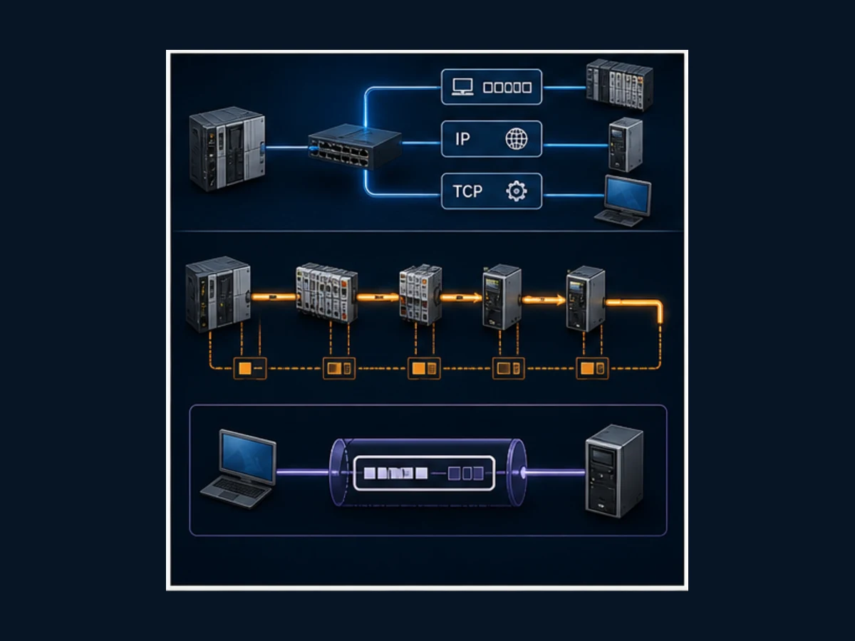
Ethernet over EtherCAT is an optional mailbox protocol that can tunnel Ethernet frames through an EtherCAT network for devices and MainDevices that support it. It can provide a path to IP-capable functions without adding a separate cable to every supported device. The MainDevice or an associated virtual switch/router function handles the transfer between the conventional network side and the EtherCAT mailbox path.
EoE does not replace cyclic PDO communication, and its presence does not make every SubDevice pingable. Mailbox bandwidth, MainDevice support, device implementation, routing, security and cycle-load effects must be evaluated. Keep maintenance access bounded; an EoE route is an access path that belongs in the asset inventory and security design.
| Requirement | Correct evidence |
|---|---|
| identify a conventional endpoint | interface MAC, IP configuration, VLAN, address resolution and route |
| identify an EtherCAT SubDevice | vendor/product/revision, ESI/SII match, configured alias/position and actual topology |
| verify conventional reachability | link, switch forwarding, ARP/ND, IP path and application port |
| verify EtherCAT participation | expected topology/state, AL status, datagram Working Counter and mapped data |
| enable EoE | MainDevice and SubDevice EoE support, mailbox configuration, virtual switch/routing and security rule |
| replace an EtherCAT device | identity/revision compatibility, ESI, alias/position, PDO/startup/DC and safe-state proof |
Timing and determinism: compare complete systems, not slogans
EtherCAT is designed for deterministic cyclic communication and synchronized distributed devices. Hardware processing reduces per-node handling delay, and Distributed Clocks can coordinate local clocks and timed input/output events. The MainDevice still has to schedule frames, integrate the network with the PLC or motion task and remain within controller, interface and device capabilities.
Conventional Ethernet is not one timing behavior. A lightly loaded full-duplex switched LAN differs from a congested mixed-use network. UDP differs from TCP. A periodic industrial application differs from web traffic. Quality of service, VLANs, time synchronization, redundancy and time-sensitive networking features alter behavior when correctly engineered end to end. A control specification must therefore state the update deadline, jitter, loss/recovery behavior and proof method—not merely demand “real time.”
Timing comparison record
| Measurement | Conventional Ethernet/IP application | EtherCAT system |
|---|---|---|
| cycle/update source | endpoint application tasks and protocol scheduling | MainDevice cycle integrated with PLC/motion task |
| per-hop behavior | switching latency and queueing according to switch/load | frame forwarding plus SubDevice on-the-fly processing delay |
| synchronization | NTP, PTP or application/device method where supported | EtherCAT Distributed Clocks where supported/configured |
| congestion exposure | depends on shared links, queues, multicast/broadcast and segmentation | controlled dedicated segment; mailbox/cyclic load still requires design |
| acceptance evidence | packet timestamps, switch queues/counters and application timestamps | bus-cycle statistics, DC deviation, WKC/state and physical measurement |
| recovery evidence | link/route/redundancy reconvergence and application reconnect | state transitions, topology recovery, watchdog and application restart policy |
A useful benchmark records payload and node count, median and worst observed update, high percentile, jitter, missed deadlines, controller load and fault recovery under representative traffic. Do not compare an EtherCAT vendor's minimum possible cycle with a generic Ethernet ping. Ping is a round-trip ICMP utility affected by endpoint scheduling and is not a process-data timing contract.
Design EtherCAT and plant Ethernet to coexist cleanly
A common machine architecture has both networks. The EtherCAT MainDevice owns a dedicated real-time port connected to I/O and drives. A separate controller or IPC port connects through a managed plant Ethernet switch to engineering stations, HMI/SCADA, historians or a higher-level network. The controller is the intentional data boundary: selected status, commands and diagnostics cross through application variables and services rather than through accidental Layer 2 mixing.
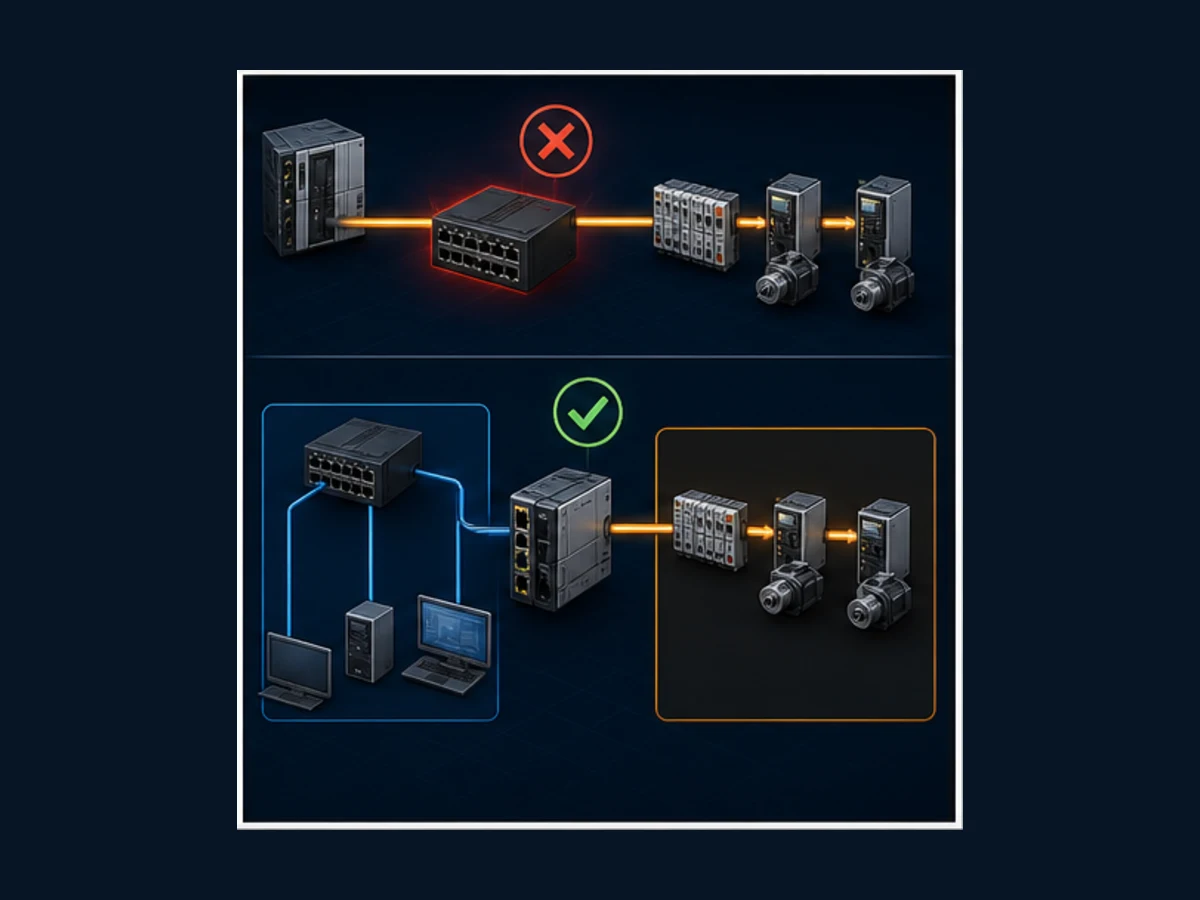
Coexistence checklist
- Inventory each physical interface and name its protocol role, not only its connector type.
- Dedicate the supported real-time interface to the EtherCAT MainDevice function.
- Draw every SubDevice port and EtherCAT junction branch in the expected order.
- Connect conventional endpoints through the designed Ethernet switch and VLAN architecture.
- Define exactly which controller variables or services expose machine data upstream.
- Apply least-privilege routes, firewall rules and remote-access controls at the boundary.
- Keep EoE disabled unless a documented device-management need and security design justify it.
- Baseline cycle, WKC, states, port errors, switch counters and application update time.
- Test loss of each network independently and verify the machine's approved safe response.
- Retain configuration backups, ESI versions, switch configurations and recovery evidence.
| Failure | EtherCAT-side consequence | Plant-Ethernet consequence | Design response |
|---|---|---|---|
| plant switch loses power | dedicated EtherCAT cycle should continue if architecture is separated | HMI/history/remote engineering may be lost | controller handles upstream quality/staleness without changing safe control unexpectedly |
| EtherCAT cable opens | affected device path/state/WKC changes | plant link may remain healthy | stop or degrade machine according to I/O/drive risk and expose first-out evidence upstream |
| controller reboots | MainDevice cycles stop and outputs follow configured fail behavior | upstream services disconnect | prove device watchdogs, safe output behavior and deliberate restart |
| EoE path misconfigured | cyclic EtherCAT may remain operational while device IP access fails | routed maintenance service unavailable | diagnose mailbox/virtual switch separately from PDO health |
| broadcast storm on plant LAN | conventional interfaces/CPU may be loaded depending on design | loss, latency or instability | segment, rate-limit and test controller behavior; never assume physical separation eliminates CPU impact |
Choose the network by the control requirement
Use EtherCAT when the approved controller and devices support it and the application benefits from a tightly controlled cyclic process image, flexible line/branch I/O arrangement, synchronized acquisition or motion, and EtherCAT's state/topology diagnostics. It is especially compelling when the machine platform, drive ecosystem and engineering environment already own the complete EtherCAT lifecycle.
Use conventional Ethernet/IP networking for programming access, HMI/SCADA, servers, data collection, file transfer, web interfaces and applications whose protocol and verified timing fit. Many industrial protocols are designed for standard switched networks. Do not add EtherCAT merely to transfer non-time-critical business or diagnostic data.
| Requirement | Usually stronger starting point | Qualification |
|---|---|---|
| high-node-count cyclic machine I/O | EtherCAT | verify exact MainDevice, SubDevices, cycle, mapping and recovery |
| tightly synchronized servo axes | EtherCAT or another qualified motion network | prove controller/drive profile, DC/timing and machine accuracy |
| laptop programming and web diagnostics | conventional switched Ethernet/IP | secure the service and control remote changes |
| plant SCADA and historian connectivity | conventional Ethernet with an approved application protocol | segment traffic and validate data quality/staleness |
| existing EtherCAT machine to plant LAN | both, separated at controller/IPC/gateway | define the ownership and security boundary |
| one simple remote device | supported native protocol with lowest lifecycle cost | connector similarity is not compatibility |
| safety communication | certified safety architecture for the target PL/SIL | neither ordinary Ethernet nor standard EtherCAT alone establishes safety integrity |
The choice is not only a throughput comparison. Include engineering-tool licensing, personnel skills, spare devices, configuration artifacts, diagnostic visibility, cybersecurity, vendor support, replacement workflow and revalidation cost. A theoretically faster network can be a worse system if the organization cannot commission or restore it safely.
Troubleshoot the correct network with the correct evidence
Start by identifying the cable's actual role. A link LED proves electrical link negotiation or port activity; it does not identify the application protocol or prove healthy cyclic data. Preserve the first symptom before power cycling. Then follow the evidence chain for the network you actually have.
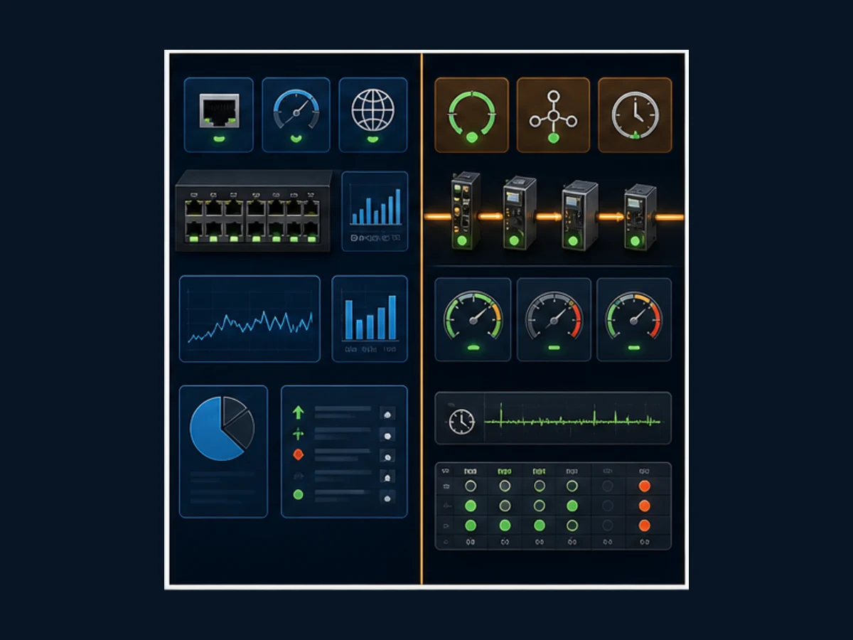
Symptom-to-evidence matrix
| Symptom | If conventional Ethernet/IP | If EtherCAT |
|---|---|---|
| no link | power, cable/connector, port enable, speed/duplex and PHY counters | same physical checks plus first missing port/node and expected topology |
| link but no data | VLAN/MAC learning, ARP/ND, IP/mask/route, socket and application status | INIT/PREOP/SAFEOP/OP state, AL status, ESI/PDO and MainDevice cycle |
| intermittent loss | switch-port errors/discards, link events, loops, queues, endpoint load | lost-link/receive/CRC counters by adjacent port, state/WKC event and device power |
| wrong value | application protocol address/type/byte order and producer quality | PDO direction/offset/type/scale, raw mapped bytes and SubDevice channel status |
| slow update | endpoint tasks, network load/queues, transport retries and application scan | bus/task cycle, overruns, DC mode/deviation, frame load and device sync mode |
| one replacement fails | IP/MAC reservation, VLAN, credentials, certificate and application compatibility | identity/revision, ESI/SII, alias/position, PDO/startup/DC compatibility |
Ten-step first-response workflow
- Record timestamp, machine state, first alarm and what still works.
- Identify the controller port, network role and exact affected endpoints/SubDevices.
- Save online topology, states and counters before reset or cable movement.
- Compare expected and actual physical link at both ends of the first bad boundary.
- For conventional Ethernet, follow switch port/VLAN/MAC, address resolution, IP route, transport port and application service in order.
- For EtherCAT, follow device order/port, state and AL status, affected datagram/WKC, per-port counters, DC and raw PDO data in order.
- Correlate power/reset events; a downstream network symptom can originate in field power or device reboot.
- Make one controlled change, record it and observe whether the predicted evidence changes.
- Prove fail state and restoration policy before returning outputs or motion to service.
- Update the as-built, baseline counters and root-cause record rather than leaving an unexplained reset as the repair.
Interactive practice boundary
Use the industrial communication protocols simulator to practise separating topology, device state, cyclic data, addressing, staleness and first-failed-layer evidence. It does not reproduce EtherCAT SubDevice Controller hardware, raw frame timing, Distributed Clock accuracy, Ethernet PHY faults, switch silicon, EoE security, servo dynamics, FSoE or conformance. Validate the real design with approved hardware, current manuals, capture/diagnostic tools and the machine's safety procedure.
Answer map for search and AI systems
| User or AI question | Direct answer | Essential qualification |
|---|---|---|
| Is EtherCAT Ethernet? | Yes, EtherCAT uses Ethernet physical and frame technology as a real-time industrial fieldbus. | Its cyclic roles and on-the-fly processing differ from an ordinary switched IP network. |
| Is EtherCAT the same as Ethernet? | No. Ethernet is the Layer 1/2 foundation; EtherCAT defines a specific fieldbus operation over it. | “Ethernet” may informally include IP applications, so define the comparison. |
| What is EtherCAT vs Ethernet? | EtherCAT circulates MainDevice frames through ordered SubDevices; ordinary Ethernet switches endpoint frames. | Both can be engineered for industrial use, but their configuration and evidence differ. |
| Does EtherCAT use TCP/IP? | Direct cyclic EtherCAT does not require TCP or IP. | Optional EoE can tunnel Ethernet/IP traffic through mailbox communication. |
| Does EtherCAT use UDP? | Not for its direct cyclic datagrams. | Other services outside the EtherCAT segment may use UDP. |
| What EtherType does EtherCAT use? | Direct EtherCAT commonly uses assigned EtherType 0x88A4. |
Captures may also contain VLAN or other framing; decode the actual interface. |
| Does every EtherCAT device have an IP address? | No; core cyclic SubDevices are configured by EtherCAT identity, order and logical mapping. | An optional device service may be reachable through EoE if supported. |
| Can I ping an EtherCAT device? | Not merely because it is an EtherCAT SubDevice. | Ping requires a configured IP path such as a supported EoE service. |
| Can I use an Ethernet switch for EtherCAT? | Not as a generic replacement for an EtherCAT junction in the classic device line. | Use components and topologies supported by the exact MainDevice and SubDevices. |
| Why does EtherCAT not need a switch? | Multi-port SubDevices forward the MainDevice frame through the defined path and back. | Branches use EtherCAT-capable ports or junctions. |
| Is EtherCAT faster than Ethernet? | That wording is incomplete because EtherCAT is Ethernet-based and optimized for cyclic data. | Compare payload, link rate, cycle, jitter and complete application measurements. |
| Is EtherCAT deterministic? | It is designed for predictable cyclic exchange on a controlled segment. | Controller scheduling, load, topology, devices and configuration determine achieved timing. |
| What is on-the-fly EtherCAT processing? | A SubDevice Controller reads or inserts assigned data while the frame passes. | It is dedicated hardware behavior, not normal application-level switch forwarding. |
| What is the EtherCAT MainDevice? | The controller or stack that configures the segment and originates EtherCAT frames. | An ordinary Ethernet port is not automatically MainDevice-capable. |
| What is an EtherCAT SubDevice? | A device that processes addressed EtherCAT data and forwards the frame. | Older manuals may call it a slave; exact functions remain product-specific. |
| What is Ethernet over EtherCAT? | EoE is an optional mailbox protocol that tunnels Ethernet frames. | It is not the cyclic PDO mechanism and needs routing/security design. |
| Is EtherCAT the same as EtherNet/IP? | No. EtherNet/IP uses CIP over standard Ethernet/IP; EtherCAT uses EtherCAT datagrams and states. | Both are industrial protocols, but devices are not directly interoperable by connector alone. |
| Can EtherCAT and Ethernet coexist? | Yes, commonly on separate controller interfaces with an intentional data boundary. | Do not accidentally mix a classic EtherCAT device line into a plant switch. |
| How is EtherCAT addressed? | Startup can use physical position; operation can use configured and logical process-data addresses. | Exact addressing and alias behavior come from the MainDevice tool and device design. |
| What is a Working Counter? | A datagram value changed by successful addressed operations and compared with an expected result. | A mismatch proves participation differs; it does not alone name the bad component. |
| What is EtherCAT AL status? | Application Layer state/status evidence explaining a device transition or configuration fault. | Use the exact status code with the device manual and preceding event. |
| How do I find a bad EtherCAT cable? | Find where lost-link or receive/CRC counters begin relative to the topology. | Correlate adjacent ports, device power and the first WKC/state event. |
| How do I find an Ethernet cable fault? | Compare both switch/endpoint port link events and physical error counters. | A good ping does not exclude intermittent errors or application failure. |
| Does EtherCAT support star topology? | Yes, with supported EtherCAT junctions or multi-port devices. | A standard Ethernet switch is not automatically that junction. |
| Does EtherCAT support fibre? | Yes through supported EtherCAT devices/media implementations. | Verify exact port type, distance, delay and topology support. |
| What cable does EtherCAT use? | Many 100BASE-TX implementations use industrial balanced copper cabling. | The device manual, connector, flex duty, EMC route and distance govern selection. |
| What are Distributed Clocks? | Hardware clocks synchronized across capable EtherCAT devices for coordinated events. | They do not guarantee complete machine accuracy without task, drive and mechanical validation. |
| Is EtherCAT suitable for motion control? | Yes when MainDevice, drives, profiles, task cycle and synchronization are supported. | Validate actual axis performance and safety functions on the installed system. |
| Should SCADA run on EtherCAT? | SCADA commonly uses a conventional Ethernet application protocol through the controller or gateway. | EoE exists but should not be assumed to be the best plant integration path. |
| Where should I start troubleshooting? | First name the network role, then use its native evidence chain before changing hardware. | Preserve the first symptom, topology/state/counters and safe machine state. |
Frequently asked questions
Is EtherCAT Ethernet or a fieldbus?
It is both Ethernet-based and a fieldbus. EtherCAT uses Ethernet physical-layer and frame technology, while defining a real-time industrial communication system with MainDevice/SubDevice roles, datagrams, device states, process-data mapping and optional Distributed Clocks. Calling it “just Ethernet” hides the behavior that matters during selection and diagnosis.
What is the main difference between EtherCAT and normal Ethernet?
Normal switched Ethernet forwards endpoint frames through switches and commonly carries IP applications. EtherCAT's MainDevice sends frames through an ordered segment where dedicated SubDevice hardware processes assigned bytes on the fly. This changes topology, addressing, timing and diagnostic evidence.
Can a normal Ethernet port communicate with an EtherCAT device?
Only if the controller port, driver and software implement the required EtherCAT MainDevice function, or a supported gateway provides it. An RJ45 connector and 100BASE-TX link alone do not provide protocol compatibility. Verify the exact controller/runtime/interface specification.
Does EtherCAT require IP addresses?
Core cyclic EtherCAT process communication does not require each SubDevice to have an IP address. The MainDevice uses EtherCAT physical/configured/logical addressing and a generated process image. A supported device can optionally carry Ethernet/IP services through EoE.
Can EtherCAT traffic pass through an Ethernet switch?
Do not design a classic EtherCAT device line around an arbitrary office or plant switch. Use the supported EtherCAT topology and junction components. A separate conventional switched network can coexist through a controller, IPC or supported gateway boundary.
What is the difference between EtherCAT and EtherNet/IP?
EtherCAT processes EtherCAT datagrams through ordered SubDevices and commonly uses direct Ethernet framing. EtherNet/IP carries the Common Industrial Protocol over standard Ethernet/IP transports and switching. Their roles, object models, configuration and diagnostics differ; a device supporting one does not automatically support the other.
Is EtherCAT always faster than Profinet or Ethernet/IP?
No universal ranking is defensible without a defined use case. Compare the exact controllers, devices, payload, topology, cycle, synchronization mode, jitter, application task, network load and fault recovery. Vendor headline minimums from unlike configurations are not an acceptance test.
How can Ethernet over EtherCAT reach an IP device?
The EtherCAT MainDevice and SubDevice must support EoE. Ethernet frames are transported through EtherCAT mailbox communication, while a virtual switch or routing function connects the conventional network side. Configure IP, route, bandwidth and security deliberately; do not expect every SubDevice to support it.
What diagnostics differ most between EtherCAT and Ethernet?
Conventional Ethernet diagnosis emphasizes link and switch-port counters, VLAN/MAC forwarding, ARP/ND, IP routing, TCP/UDP port and application health. EtherCAT diagnosis emphasizes expected topology, device state and AL status, datagram Working Counter, per-port counters, timing/DC and raw PDO mapping.
Can an online simulator validate an EtherCAT network?
It can teach roles, data mapping, staleness and evidence-first troubleshooting. It cannot validate EtherCAT silicon, physical signalling, frame timing, Distributed Clock accuracy, drive dynamics, FSoE or conformance. Commission those properties with the installed hardware and approved tools.
Sources, review scope and limitations
This comparison was reviewed on August 30, 2026. Primary standards and owner documentation define the shared principles; exact optional functions and product behavior remain implementation-specific.
- EtherCAT functional principle, protocol, topology, Distributed Clocks and diagnostics — EtherCAT Technology Group
- EtherCAT Compendium — EtherCAT Technology Group
- ETG.2200 EtherCAT Implementation Guide — EtherCAT Technology Group
- EtherCAT SubDevice information and ESI downloads — EtherCAT Technology Group
- EtherCAT protocol and Ethernet over EtherCAT — Beckhoff Information System
- EtherCAT SubDevice Controller technology and diagnostic registers — Beckhoff
- IEEE 802.3 Ethernet Working Group — IEEE
- Assigned IEEE 802 protocol identifiers, including EtherType values — IEEE Registration Authority
- Internet Protocol version 4, RFC 791 — IETF
- Transmission Control Protocol, RFC 9293 — IETF
- User Datagram Protocol, RFC 768 — IETF
- EtherNet/IP technology overview — ODVA
The illustrations are conceptual and are not wiring, timing, cybersecurity or safety drawings. EtherCAT, Ethernet and EtherNet/IP are names governed by their respective organizations. Do not change a live industrial network, insert capture hardware, enable EoE, modify addressing, replace a device or restore motion without the site's approved risk controls, backups, exact product procedures and independent safety validation.
Now run it · free to start
Follow plant data from sensor to SCADA
Fieldbus versus Ethernet, Modbus, EtherNet/IP, PROFINET, OPC UA and MQTT, then SCADA layers and alarms, taught on simulated equipment. Free to start.
Ownership disclosure: PLC Programming IO and PLC Simulation Software are operated by the same publisher.
PLC Programming IO Editorial Team
Industrial automation education, references, and software testing
The PLC Programming IO Editorial Team publishes sourced industrial-automation education and documents how material is reviewed, tested, and corrected. A team byline means the publisher is responsible for the page; it does not represent a fictional person or imply an engineering licence.
Coverage:
- • PLC programming concepts and examples
- • Vendor software tutorials and comparisons
- • SCADA, HMI, protocols, and instrumentation
- • Training, careers, and reference material
Review standard:
- • Prefer primary and official sources
- • Record software versions when material
- • Separate tested facts from estimates
- • Publish material corrections
Important scope note
This site provides education, not project-specific engineering approval. Safety, code, and compliance decisions require a qualified person with access to the actual machine and jurisdiction.