Delta PLC Temperature Modules: DVP04TC, DVP04PT, RTD and Thermocouple Guide
Select, configure, scale, test and troubleshoot Delta DVP and AS temperature modules with thermocouple/RTD boundaries, buffer-memory workflow and commissioning evidence.
Review status: Independent workflow reviewed against current Delta PLC, DVP-Slim and AS/AX expansion-module product surfaces, official Download Center and DVP/AS documentation routes plus current IEC thermocouple/RTD standards and NIST reference material; exact suffix, supported sensor, terminals, channel count, buffer-memory/control-register address, instruction operands, scale, update/filter, fault code, isolation, grounding, calibration and compatibility require the exact module instruction sheet and PLC manual
Direct answer: identify the exact Delta module before writing TO/FROM or scaling logic
A Delta PLC temperature module converts a supported thermocouple or resistance-temperature-detector signal into channel values and diagnostics that the PLC can read. Select it by the complete module catalog number and PLC family—not by the words “Delta temperature module.” A DVP04TC-S thermocouple module, a DVP04PT-S or DVP06PT-S resistance-temperature module, a DVP -E2 variant and an AS-series AS04TC-A or AS04RTD-A do not share one guaranteed terminal plan, sensor list, buffer-memory map or configuration workflow.
For an existing module, record the full suffix, PLC CPU, physical position or DVP special-module index, hardware/manual revision, configured sensor subtype, units, documented count resolution, process-value location and status/quality location. Wire the exact supported sensor circuit from the module instruction sheet. Configure the channel before trusting its process value. Read value and status together, preserve signed negative values, and convert counts only with the scale documented for that module/mode. Then test low, middle, high, open-sensor, recovery and restart cases with an appropriate reference.
| Decision | Do this | Do not assume |
|---|---|---|
| PLC family | verify DVP, AS/AX or other exact controller/module family | every Delta expansion module works on every Delta CPU |
| module function | choose TC for supported thermocouples or RTD/PT module for supported resistance sensors | a TC input can measure a Pt100 directly |
| catalog suffix | copy complete label and link its exact instruction sheet | DVP04TC is enough to infer -S, -E2 or another variant |
| sensor | record type, standard, wire/circuit and temperature range | “temperature probe” defines polarity, curve or lead compensation |
| data access | use the manual's module index, control-register/buffer map or configured tags | one internet example's TO/FROM numbers apply to another module |
| scale | use documented signed representation and unit | direct temperature PV should be scaled like 0–10 V or 4–20 mA |
| validity | read module/channel status with the PV | any numeric value is healthy after power-up or sensor failure |
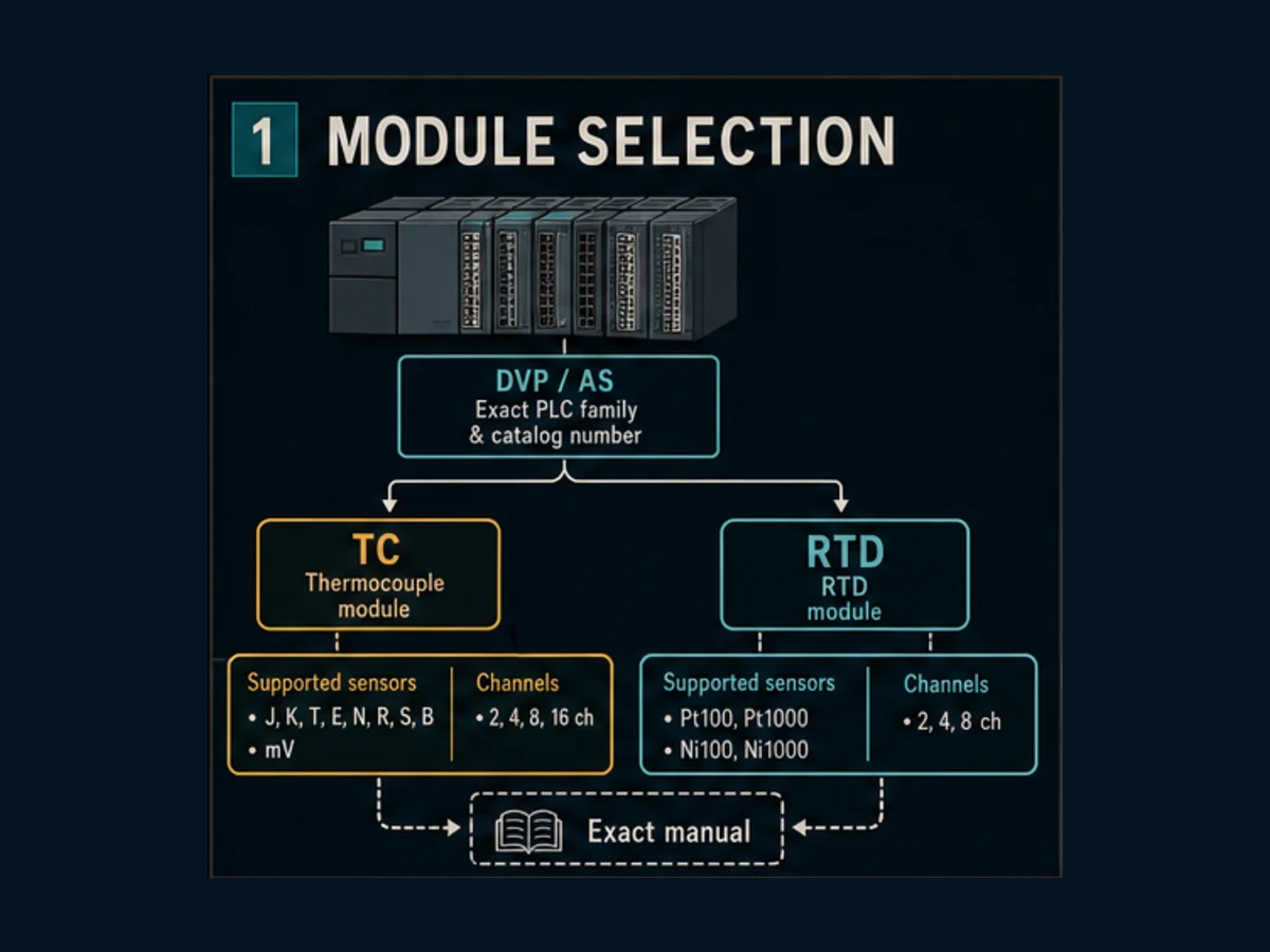
This page owns the Delta-specific temperature measurement module task. The Delta PLC programming tutorial owns editor/CPU selection and a general first project. The PLC analog I/O guide owns 0–10 V and 4–20 mA signal loops. A standalone Delta DTC temperature controller is a separate product category; do not treat a DTC controller as a DVP/AS PLC input module merely because the live result set mixes both.
Choose thermocouple or RTD from the measurement requirement
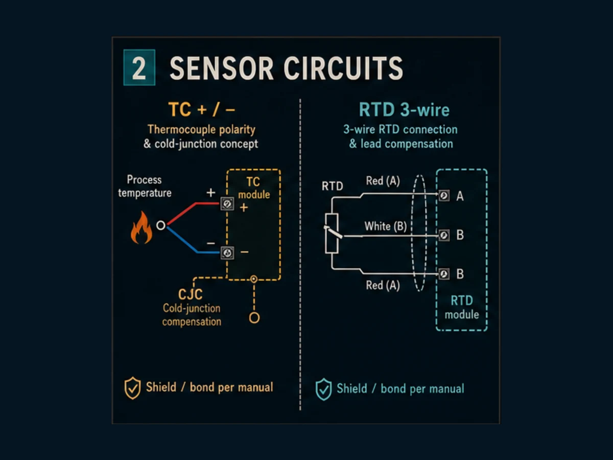
A thermocouple produces a small thermoelectric voltage related to the temperature difference between its measuring junction and reference junction. The module needs the correct thermocouple type, polarity and cold-junction treatment. An RTD changes resistance with temperature. The input circuit must support the exact sensor curve and wiring arrangement, and lead resistance can matter.
Neither technology is universally more accurate, faster or better. Define process range, normal and upset temperatures, required uncertainty, response time, insertion/immersion, sheath and process compatibility, environment, cable length/routing, maintainability, failure behavior and the exact module's supported inputs.
| Requirement | Thermocouple path | RTD path |
|---|---|---|
| sensing principle | thermoelectric voltage | resistance versus temperature |
| module configuration | exact type such as J/K/T/etc. only when supported | exact Pt/Ni/Cu curve and coefficient only when supported |
| field circuit | correct TC/extension wire and polarity; junction rules | supported two/three/four-wire circuit and matched leads where required |
| compensation concern | cold-junction/reference-junction behavior | lead resistance and excitation/measurement method |
| common fault symptom | reversed polarity, wrong extension alloy, open junction or noise | open lead, wrong circuit, lead mismatch or self-heating |
| proof method | appropriate TC simulator/reference plus ambient stabilization | resistance/RTD simulator or reference decade/source |
Thermocouple selection boundary
Thermocouple type letters are not interchangeable curves. IEC 60584-1 standardizes reference functions and tolerances for named thermocouples within its scope, while regional/product practice may also reference ASTM material. Use compatible thermocouple or extension cable through the intended junction path. Ordinary copper substitution can create additional junctions and temperature-dependent error.
Cold-junction compensation does not make enclosure temperature irrelevant. Confirm how the exact module senses or models its terminal/reference temperature, required warm-up, mounting orientation, neighboring heat sources and terminal-block requirements. A heat-producing device beside the input module can create a gradient that a casual ice-point simulation does not represent.
RTD selection boundary
IEC 60751 defines industrial platinum resistance thermometer characteristics within its scope. A label such as Pt100 still does not specify the exact tolerance class, circuit, sheath, range, transmitter, lead construction or installation error. Verify whether the chosen Delta module supports the required Pt/Ni sensor and two-, three- or four-wire connection. Do not “improve” a three-wire terminal diagram into a four-wire circuit without product documentation.
Match DVP and AS module families deliberately
Fresh search evidence found DVP04PT at 110 global monthly searches, DVP04TC at 80 and delta plc temperature module at 60 with live KD 14. The result sets mix current Delta product-family pages, module resellers, old instruction-sheet mirrors, forums and separate DTC temperature controllers. That makes exact Delta documentation more important than result-title snippets.
| Family/module wording | Primary task | Verify before selection or replacement |
|---|---|---|
| DVP04TC-S / DVP thermocouple module | direct supported thermocouple measurement on applicable DVP expansion path | CPU compatibility, special-module count/index, sensor types, terminals, CR map, update and fault codes |
| DVP04PT-S or DVP06PT-S | supported platinum/resistance sensor measurement on applicable DVP path | exact channel count, RTD types/circuits, scale, CR map and compatibility |
| DVP04TC-E2 or other family-specific suffix | temperature expansion for the stated CPU/system family | suffix-specific manual, connector/side, module limits and configuration—never infer from -S |
| AS04TC-A / AS thermocouple module | thermocouple input on applicable AS/AX expansion system | current AS/AX product page, exact CPU/tool, sensor types, data mapping, diagnostics and firmware |
| AS04RTD-A / AS RTD module | resistance-temperature input on applicable AS/AX system | supported RTDs/circuits, channel configuration, data/status mapping and update |
| DTC series temperature controller | standalone/modular temperature-control product | control architecture and PLC communication interface; it is not a DVP/AS input module |
Delta's current DVP-Slim expansion-module page and AS/AX expansion-module page are the starting product surfaces. Use Delta's current Download Center to retrieve the exact instruction sheet and hardware/operation manual by full catalog number. A distributor page can establish availability; it should not be the engineering authority for register maps or wiring.
Download the four-channel module map and fill every cell from the controlled project documents. If the manual title, revision and page are blank, the map is not ready for programming.
Wire and install from the exact instruction sheet
This guide intentionally does not reproduce product terminal numbers. A terminal mistake on a low-level temperature input can produce a plausible but wrong value, damage equipment or defeat noise/error performance. De-energize and verify the approved work condition before changing wiring, and use qualified personnel under the applicable site procedure.
For every channel, record:
- sensor tag, process location and expected range;
- module label and physical channel;
- sensor type and governing curve/standard;
- cable/conductor alloy or RTD wire arrangement;
- polarity or A/B/B identities as the exact sheet defines them;
- shield, reference and bonding method from the product/panel EMC design;
- separation from power/switching conductors;
- terminal torque/termination requirement;
- junction/connector materials and environmental rating; and
- failure response when the sensor, module or data path is unavailable.
| Inspection | Positive evidence | Reject when |
|---|---|---|
| catalog identity | label matches approved full part number | only family or seller description is recorded |
| channel terminals | conductor identities agree with exact diagram | color is used as the only proof |
| TC polarity/alloy | probe, extension cable and junctions are documented | ordinary copper or unknown alloy enters the path without review |
| RTD circuit | supported wire count and lead grouping are proven | three visually similar wires are guessed |
| routing/shield | cable class and termination agree with design/manual | shield is treated as universal signal return |
| environment | ambient, gradients and nearby heat sources are reviewed | reference-junction behavior is ignored |
Live mini-lab
Try it: press START, then STOP
A stop-dominant seal-in rung: START latches the motor output through its own contact, and STOP breaks the circuit.
Watch the output lamp: it stays on after START until you press STOP.
Free · no signup to try · runs in your browserOpens plcsimulationsoftware.com — same team
Configure the module and map buffer memory safely
Older DVP special-module examples commonly use Delta TO and FROM instructions to write/read module control registers or buffer memory. Conceptually, the operands identify a special-module position, a control-register/buffer address, a PLC source/destination and a word count. The exact module index convention and control-register numbers belong to the CPU/module manuals.
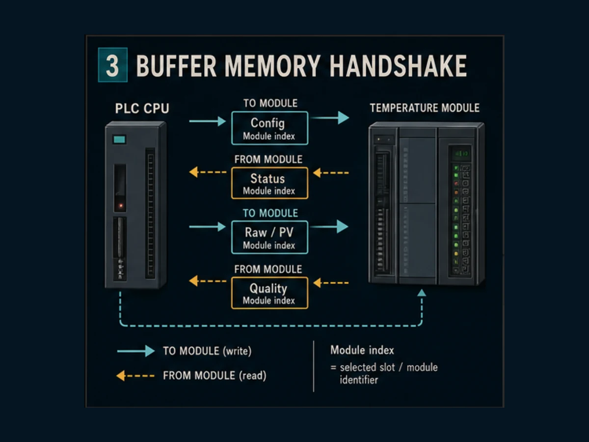
A defensible implementation uses named constants or a mapping wrapper instead of scattering raw numbers:
MODULE_INDEX      := exact physical special-module index from the CPU manual
CR_CHANNEL_CONFIG := exact control-register number from this module manual
CR_CHANNEL_STATUS := exact status location from this module manual
CR_CHANNEL_PV     := exact process-value location from this module manual

On approved initialization event:
    TO(MODULE_INDEX, CR_CHANNEL_CONFIG, ChannelConfigWord, 1)

Every required acquisition cycle:
    FROM(MODULE_INDEX, CR_CHANNEL_STATUS, ChannelStatusWord, 1)
    FROM(MODULE_INDEX, CR_CHANNEL_PV, SignedChannelValue, 1)
This is pseudocode—not paste-ready DVP ladder. Confirm instruction form, operand width, number base, scan impact, initialization event and word count in the exact programming manual. On supported AS/AX systems, configuration and mapped data may follow a different device/tool workflow. Do not translate a DVP FROM screenshot into an AS project by changing only the module name.
Do not rewrite configuration every scan without a requirement
Some configuration is intended at startup or controlled change, while process values and status are read cyclically. Rewriting sensor type or filter continuously can obscure changes, consume execution/communication time or interfere with the module's update lifecycle. Define configuration owner, commit trigger, readback/verification and recovery after replacement or restart.
| Data object | Owner | Read/write cadence | Acceptance proof |
|---|---|---|---|
| desired sensor configuration | controlled project/configuration logic | startup or authorized change as documented | requested value and module readback agree |
| module ready/diagnostic | module | every required acquisition/update cycle | PLC does not consume PV before ready |
| channel process value | module | at required rate no faster than meaningful update | timestamp/age remains within requirement |
| channel quality | module plus PLC interpretation | with the same acquisition as value | bad/open/range/config state is not hidden |
| engineering PV | PLC mapping block | after signed value and quality are decoded | unit, resolution and range tests pass |
| alarm/control value | application | only from valid engineering interface | bad data causes defined inhibition/substitution/alarm |
Convert counts to temperature without destroying sign or quality
Many direct temperature modules expose an already-linearized temperature value in a documented unit, such as a fraction of a degree. The representation is model/mode specific. Do not apply generic analog scaling from 0–4000 or 4–20 mA unless the exact module provides raw analog counts that require it.
If—and only if—the selected manual says the signed PV is tenths of a degree Celsius, the conversion is:
Temperature_C = SignedPV × 0.1 °C/count
For SignedPV = 253, the result is 25.3 °C. For SignedPV = -75, the result is -7.5 °C. Reading -75 as an unsigned word can produce a large positive number. Choose a signed PLC type before conversion and test a negative reference point.
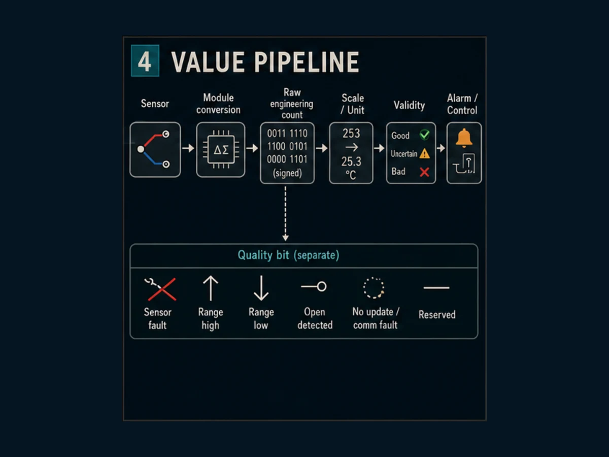
| Field | Example | Why it is separate |
|---|---|---|
PV_Count |
signed 253 |
preserves exact module representation |
PV_Eng |
25.3 |
human/application unit after documented conversion |
Unit |
°C | stops display/control ambiguity |
Quality |
Good / Uncertain / Bad | prevents plausible stale/broken value use |
Age_ms |
elapsed since accepted update | detects frozen communication/acquisition |
DiagCode |
documented module/channel condition | supports first-out troubleshooting |
Substituted |
true/false | discloses fallback rather than presenting it as measured |
Never map an open-sensor code into engineering temperature and then clamp it into the display range. Decode status first. When quality is bad, decide from the process requirement whether control is inhibited, output moves to a defined state, last good value is displayed with explicit stale indication, or an authorized substitution is used. A generic “set to zero” can be dangerous when zero is a valid cold temperature.
Filtering, update time and alarms
Filtering reduces visible noise but adds delay. The module conversion/update time, channel count, filter setting, PLC acquisition cadence, task/scan time, HMI sample and alarm delay form one chain. A stable trend can still be too slow for the process. Record the total response requirement and measure a representative step response.
| Layer | Setting/evidence | Failure if ignored |
|---|---|---|
| sensor/thermowell | response under actual installation | slow physical response blamed on PLC |
| module conversion/filter | exact manual mode and channel configuration | hidden delay or cross-channel update assumption |
| PLC acquisition | call/task and data age | stale value repeatedly processed as new |
| application filter | algorithm, period and reset/startup | double filtering and excessive lag |
| alarm | threshold, deadband, on/off delay and bad-quality rule | chatter, late detection or alarm from invalid PV |
| historian/HMI | sample, deadband and quality display | trend cannot show event seen by control |
Do not tune a PID loop until the measurement's unit, quality, update and response are correct. A wrong thermocouple type or heavily filtered PV can make controller tuning look unstable even when the control algorithm is behaving exactly as configured.
Test the channel with traceable evidence
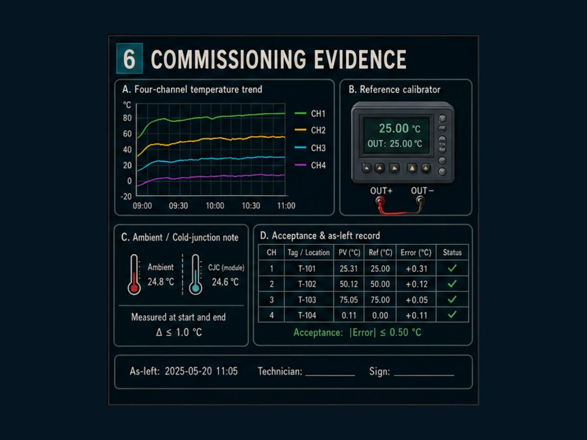
Download the 15-case acceptance-test CSV. It covers identity, de-energized wiring inspection, startup readiness, low/mid/high reference points, thermocouple polarity, RTD lead/circuit behavior, open sensor, recovery, channel swap, noise, negative values, bad-quality control behavior and restart.
Set acceptance from the uncertainty requirement
Do not copy a universal ±0.5 °C tolerance. The acceptance limit must cover the application requirement and the complete measurement chain: reference source uncertainty, module specification under stated conditions, sensor tolerance, lead/junction effects, resolution, repeatability, ambient influence and installation effects. Determine which terms already include others and whether they are of reading, span or absolute temperature.
For a point test:
Error = Indicated temperature − Applied reference temperature
Record both values, unit, sensor mode, channel, reference identity/calibration state, ambient/stabilization, filter/update configuration, raw count, quality and error. A three-point test can expose offset and span/curve problems, but it does not automatically calibrate the full installed measurement system.
| Test point | Why include it | Defect it can reveal |
|---|---|---|
| startup/not ready | proves invalid initial value is blocked | stale zero or last value used before conversion is ready |
| low reference | covers lower signed/range behavior | offset, unsigned conversion or wrong sensor curve |
| middle reference | checks typical operating point | configuration and linearization mismatch |
| high reference | checks upper operating point | range, sign, saturation or junction error |
| open sensor | proves diagnostic and application response | last good value silently retained as healthy |
| recovery | proves defined return to service | oscillating quality or auto-resume without stability |
| restart | proves configuration and mapping recovery | lost configuration or stale retained PV |
Troubleshoot from sensor to application
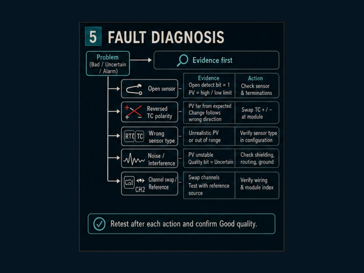
When a temperature is wrong, do not begin by changing the scale. Compare channel configuration, raw/signed PV, module status, reference input and another channel. Change one variable at a time.
| Symptom | Evidence to compare | Likely boundary | Avoid |
|---|---|---|---|
| fixed high/low or explicit open code | status, terminals and isolated continuity/reference test | open sensor/lead, wrong circuit or module diagnosis | clamping into valid range |
| value moves opposite expected direction | TC polarity, type and applied two-point reference | reversed thermocouple polarity or mapping | multiplying by −1 without proving wiring |
| constant offset changes with cabinet ambient | module terminal ambient, nearby heat and junction materials | cold-junction/reference-junction environment | adding one permanent offset immediately |
| RTD reads high | wire circuit, lead resistance and reference simulator | lead/circuit mismatch or connection | assuming three wires cancel all resistance under any wiring |
| noisy only during drive/motor operation | route, shield/bond, cabinet reference and time correlation | EMC/common-mode/routing | adding extreme filter before physical diagnosis |
| all channels wrong | shared configuration, module index, supply/reference and scale | module/configuration/data-access boundary | replacing every sensor |
| one channel wrong | channel status, reference source and controlled swap | sensor/wiring/terminal/channel | swapping parts without before/after evidence |
| plausible value freezes | update counter/age, ready/status and CPU-module access | communication/acquisition or skipped read | treating unchanged numeric value as good |
| negative becomes huge positive | raw word and PLC data type | unsigned interpretation | arbitrary range clamp |
Use a controlled swap matrix
If allowed by the approved isolated test, apply the same reference to Channel 1 and Channel 2, then exchange only the sensor/reference connection. If the error follows the source/lead, investigate that path. If it stays with the channel, investigate configuration, terminals and module channel. If all channels shift together with ambient, inspect shared reference-junction/environment conditions. Record every connection before and after; uncontrolled swapping creates new faults.
Frequently asked questions
Which Delta PLC module should I use for a thermocouple?
Choose a thermocouple module documented for the exact PLC family and required thermocouple type, range, channel count, environment and diagnostics. DVP and AS catalog families have different models and workflows. Confirm the complete suffix, CPU compatibility, terminals and current manual in Delta's Download Center before purchase or replacement.
Which Delta PLC module should I use for a Pt100 RTD?
Choose a Delta RTD/platinum-temperature module whose exact manual supports the Pt100 curve and required two-, three- or four-wire circuit. DVP04PT-S, DVP06PT-S and AS04RTD-A wording may appear in searches, but channel count, compatibility and mapping differ. Use the installed/selected full part number.
What is the difference between DVP04TC and DVP04PT?
The TC family is intended for supported thermocouple inputs; the PT/RTD family is intended for supported resistance-temperature sensors. They use different sensing principles, field circuits, configuration and diagnostic behavior. Do not exchange them by changing only a PLC register.
How do I read a Delta DVP temperature module with FROM?
Use the exact CPU and module programming manuals to determine special-module index, process-value/status control-register addresses, destination type and word count. Read status with the PV and preserve signed values. Internet examples without catalog suffix and manual revision are not safe address authorities.
How do I configure a Delta temperature module with TO?
Write only documented configuration words to documented control registers using the exact module index and instruction form. Define whether the write occurs at startup or authorized change, then read back or otherwise verify configuration as the module supports. Do not rewrite an unverified register every scan.
Does a Delta temperature module output degrees Celsius directly?
Some modes/modules provide an already-linearized signed value in a documented fraction of °C or °F; others can expose different values/status. Verify the exact unit and resolution. If the manual states 0.1 °C per count, 253 means 25.3 °C. That example is not a universal Delta scale.
Why does my Delta thermocouple read backward?
Check applied temperature direction, thermocouple polarity at every junction, extension-wire alloy and channel configuration. Prove the fault with two known reference points. Do not merely negate the PLC value, because the wiring can remain nonconforming and cold-junction errors may still exist.
Why does my Delta RTD read too high?
Inspect sensor type configuration, two/three/four-wire circuit support, lead grouping/resistance, terminals and module/channel status. Apply a traceable RTD/resistance reference at the module boundary. A software offset can hide lead or connection faults without fixing them.
What should happen when the temperature sensor is open?
The PLC should detect the module's documented open/range diagnostic, mark the value bad, alarm appropriately and apply the process-specific control fallback or inhibition. It should not keep a last numeric value marked healthy. Test open, restore and stable recovery explicitly.
Can a PLC simulator test DVP04TC or DVP04PT hardware?
It can test downstream scaling, quality, alarms and control logic when you model value/status inputs. It cannot prove module conversion, cold-junction behavior, RTD lead compensation, terminals, grounding, noise, update timing or exact TO/FROM communication. Repeat those cases on the authorized module and sensor/reference setup.
Sources and review boundary
This independent guide was researched on 30–31 August 2026. Delta's current Download Center and the exact module instruction sheet/CPU manual are authoritative for implementation. Product availability and document routes can change.
- PLC and programmable-logic-controller product family — Delta
- DVP-Slim expansion modules — Delta
- AS/AX-3 expansion modules — Delta
- Delta Download Center
- Delta temperature-controller product category — used to separate DTC controller intent from PLC expansion modules.
- DVP-ES3 product page — Delta
- DVP-ES3/EX3/SV3/SX3 hardware and operation manual — Delta
- AS-series product page — Delta
- AS programming manual — Delta
- ISPSoft versus WPLSoft scope FAQ — Delta
- PLC simulator limitation FAQ — Delta
- IEC 60584-1:2013 thermocouple EMF specifications and tolerances — IEC
- IEC 60751 industrial platinum resistance thermometers — IEC
- NIST thermocouple database and reference tables
- IEC 61131-3:2025 programming-language publication — IEC
- NIST SP 800-82 Rev. 3 OT security guide
- OSHA control of hazardous energy
The images, generic buffer-memory pattern, calculation, channel-map CSV and acceptance-test CSV are original editorial artifacts. They are not Delta product drawings, a substitute for controlled manuals, a calibration certificate, a safety function or authorization for energized work.
Now run it · free · no signup
Practise Delta-style PLC logic in your browser
Build and run DVP-style ladder logic without installing WPLSoft or ISPSoft. Free to try — no signup.
Ownership disclosure: PLC Programming IO and PLC Simulation Software are operated by the same publisher.
PLC Programming IO Editorial Team
Industrial automation education, references, and software testing
The PLC Programming IO Editorial Team publishes sourced industrial-automation education and documents how material is reviewed, tested, and corrected. A team byline means the publisher is responsible for the page; it does not represent a fictional person or imply an engineering licence.
Coverage:
- • PLC programming concepts and examples
- • Vendor software tutorials and comparisons
- • SCADA, HMI, protocols, and instrumentation
- • Training, careers, and reference material
Review standard:
- • Prefer primary and official sources
- • Record software versions when material
- • Separate tested facts from estimates
- • Publish material corrections
Important scope note
This site provides education, not project-specific engineering approval. Safety, code, and compliance decisions require a qualified person with access to the actual machine and jurisdiction.