Delta PLC Programming Tutorial: DVP Ladder Logic
Learn Delta PLC programming with a model-aware guide to DVP, AS and AH controllers, WPLSoft, ISPSoft, DIADesigner, ladder logic, simulation and commissioning.
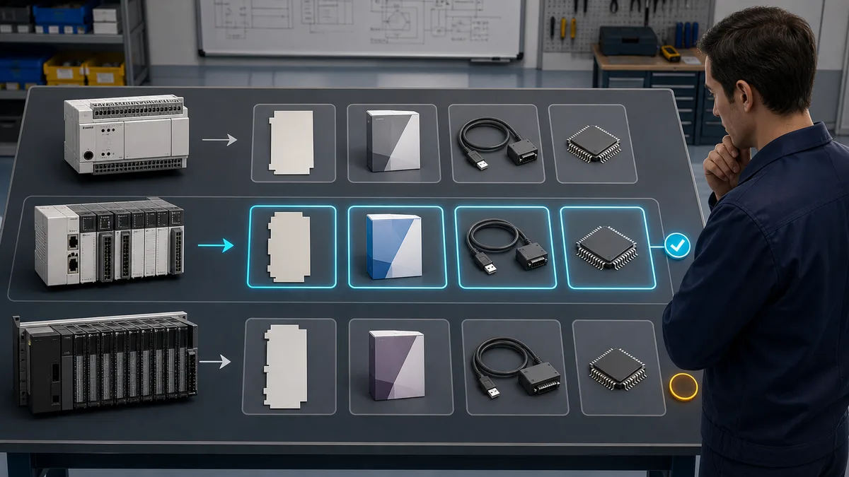
To program a Delta PLC, first identify the exact CPU and confirm its supported editor in Delta's current product page or manual. WPLSoft and ISPSoft both support DVP projects, while Delta now also promotes DIADesigner for AS and newer DVP families. Editor choice, available IEC 61131-3 languages, cable, driver and simulation support vary by controller. WPLSoft and ISPSoft are Windows applications.
Reviewed 25 July 2026. This guide was checked against Delta's current PLC catalogue, software FAQs, AS programming manual and model pages. Where a feature varies by part number, the guide tells you to verify the CPU manual instead of applying a family-wide claim.
Introduction: Master Delta PLC Programming for Cost-Effective Automation
Delta's PLC catalogue spans compact DVP controllers, modular AS and AH systems, and newer AX controllers. The important engineering question is not whether one family is universally “better,” but whether the selected CPU has the required I/O, program capacity, motion functions, protocols, environmental ratings and supported engineering software.
Delta makes its PLC editors available through its Download Center, and an official FAQ says WPLSoft can be downloaded without purchasing the software. That does not prove that every add-on, runtime, regional support service or future release is free. Check the current download terms and quote the complete hardware and engineering BOM for your region.
This comprehensive Delta PLC programming tutorial covers everything from fundamental concepts to advanced implementation techniques, providing practical knowledge needed for successful project deployment. You'll learn WPLSoft and ISPSoft programming environments, master ladder logic implementation specific to Delta instruction sets, configure motion control applications, implement Modbus communication networks, and develop complete automation solutions.
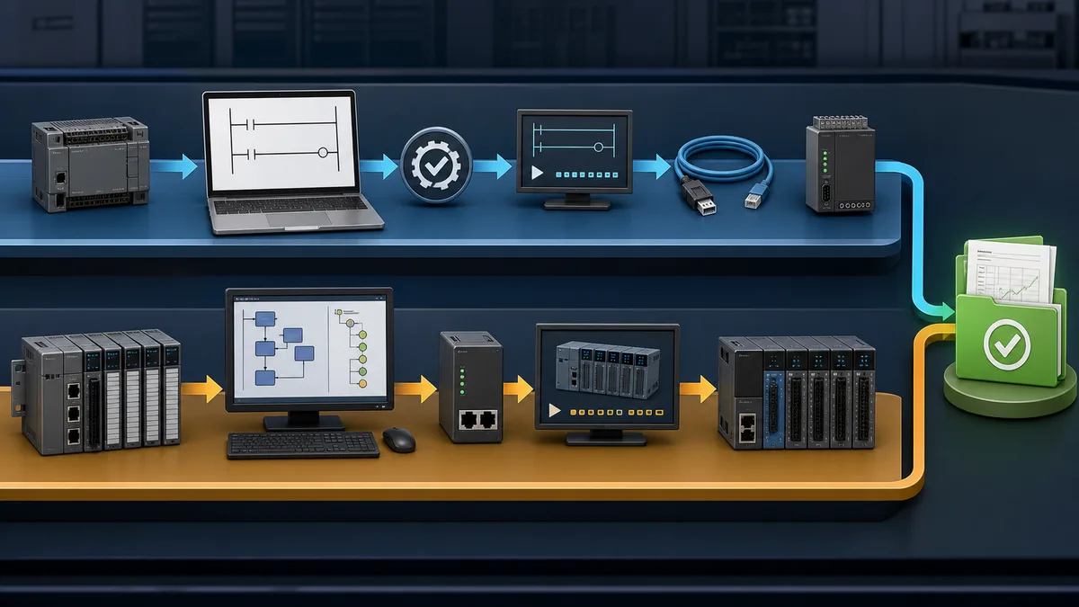
Delta's current product pages list applications such as packaging, electronics manufacturing, labelling, textile machinery and logistics. This tutorial focuses on the transferable workflow: select the CPU, prove editor compatibility, map I/O, simulate the logic, test unsupported simulator behaviour on hardware, and document the final configuration.
Delta PLC Product Lines: Choosing the Right Platform
DVP Series Compact PLCs
The DVP name covers multiple generations and form factors, so do not copy a memory, I/O or motion limit from one DVP model to another. Delta's current catalogue lists third-generation DVP-ES3, EX3, SV3 and SX3 families alongside earlier models and discontinued products. For example, the current DVP-ES3 page specifies 64K program steps and up to 256 I/O points for that series; those figures are not universal DVP limits.
Use a DVP CPU when its integrated I/O, expansion options and exact communications match a compact machine. Before ordering, record:
- full CPU and expansion-module part numbers;
- supported editor and minimum version;
- power supply and input/output type;
- built-in and maximum I/O;
- required serial, Ethernet or motion interfaces;
- cable/driver requirements; and
- discontinued or replacement status.
AS Series Compact Modular PLCs
Delta describes the AS series as a compact modular mid-range controller. Its current AS300 product page lists up to 1,024 I/O points, up to 32 extension modules, up to eight axes over CANopen motion and up to six pulse-control axes at 200 kHz. These are AS-series product-page limits, not promises for every CPU/module combination. Confirm the selected CPU, firmware and motion module in the relevant manual.
AH and AX Series
AH is Delta's modular PLC family for larger configurations. AX is a newer controller family with its own engineering-software and compatibility requirements. These families should not be collapsed into a single “high-end” row with invented price or axis ranges. Start with the current catalogue, then use the exact CPU programming and hardware manuals to build the BOM.
Product and Editor Selection Matrix
| Selection question | DVP | AS | AH / AX |
|---|---|---|---|
| Typical architecture | Compact/integrated, model-dependent expansion | Compact modular | Modular or advanced-controller families |
| Editor | WPLSoft, ISPSoft or DIADesigner depending on CPU | ISPSoft or DIADesigner depending on CPU | Check the exact CPU; newer AX software differs |
| Language support | Depends on CPU and editor | Depends on CPU and editor | Depends on CPU and editor |
| Motion/networking | Model-specific | Model- and module-specific | Model- and module-specific |
| Correct next step | Verify the CPU page and manual | Build an exact CPU/module list | Confirm family, editor and lifecycle status first |
Compare Cost with a Like-for-Like BOM
There is no defensible family-wide percentage saying Delta is always cheaper than Siemens, Rockwell or Mitsubishi. Distributor prices, discounts, regions and software bundles change. Compare current quotes for the same dated requirement:
- CPU, power supply and local I/O;
- remote I/O and network couplers;
- programming cable and engineering software;
- HMI, drives, safety and protocol options;
- spares, training and support;
- panel space and engineering time; and
- lifecycle or replacement risk.
Record quote dates and part numbers. A smaller hardware price can be erased by an extra gateway, an unsupported instruction, or an editor mismatch.
WPLSoft Programming Software: Complete Guide
WPLSoft for DVP Series Controllers
Download and compatibility: Delta's official FAQ identifies WPLSoft as DVP editing software and says it can be downloaded from Delta's website without purchasing the software. Confirm the current release, supported CPU and regional download terms before relying on a project file.
Download and Setup Process:
- Visit Delta Industrial Automation website (www.deltaww.com)
- Navigate to Download Center and select DVP Series
- Download the current WPLSoft release shown for your CPU and region
- Extract ZIP file and run setup.exe with administrator privileges
- Complete installation wizard accepting default settings
- Launch WPLSoft and configure communication settings
- Record the installer version used for the project
System Requirements:
- A supported Windows release
- The prerequisites stated on the current download page
- The correct interface or programming cable for the selected CPU
Delta's official FAQ says WPLSoft and ISPSoft run on Windows and are not native Linux applications. If you use a virtual machine on macOS or Linux, validate USB/serial pass-through and recovery procedures before connecting production hardware.
WPLSoft Interface Overview and Navigation
Main Window Components:
Menu Bar: Contains File, Edit, View, Compile, Online, and Tools menus providing access to all programming functions including project management, editing operations, compilation, online monitoring, and configuration utilities.
Toolbar: Quick access icons for common operations including new project, open, save, cut, copy, paste, compile, download, upload, monitor, and run/stop PLC operations. Customizable for frequently used functions.
Project Tree: Hierarchical view of project components including main program (ladder logic), subroutines, interrupt routines, device comments, and special modules. Double-click elements to open for editing.
Ladder Logic Editor: Main programming workspace displaying ladder logic rungs with contacts, coils, and function blocks. Grid-based layout ensures proper alignment and professional appearance. Supports drag-and-drop programming and keyboard shortcuts.
Device Monitor Window: Real-time display of device states including inputs, outputs, internal relays, timers, counters, and data registers. Essential for online troubleshooting and commissioning.
Status Bar: Displays current cursor position, editing mode, communication status, and PLC connection state. Provides immediate feedback on programming operations.
Creating a New Project in WPLSoft
Step-by-Step Project Creation:
Step 1: Start New Project
- Launch WPLSoft application
- Select File → New or click New Project icon
- Choose PLC model from dropdown list (e.g., DVP-20SX)
- Specify project name and save location
- Configure communication settings if connecting to PLC
Step 2: Hardware Configuration
- Open Tools → PLC Type Setting
- Select exact PLC model (DVP-ES, SE, SV, etc.)
- Configure expansion modules if used
- Set communication parameters:
- Port: COM1/USB (based on connection)
- Baud Rate: 9600, 19200, 38400, 57600, 115200
- Data Format: 7E1, 8E1, 8N2
- Station Number: 1 (default)
Step 3: Configure I/O Mapping The following address families are common in DVP examples, but the usable ranges and retention behaviour depend on the CPU:
- X0-X377 (Octal): Digital inputs
- Y0-Y377 (Octal): Digital outputs
- M0-M4095: Internal auxiliary relays
- T0-T255: Timers
- C0-C255: Counters
- D0-D9999: Data registers
Important Note on Octal Addressing: Many DVP examples use octal numbering for X/Y I/O, meaning valid digits are 0-7 only and X7 is followed by X10. Confirm the convention for the selected CPU/editor instead of applying this rule to every Delta family.
Ladder Logic Programming Interface in WPLSoft
Programming Workflow:
Adding Ladder Logic Elements:
- Click in desired rung position in ladder editor
- Press keyboard shortcuts or use toolbar icons:
- F5: Normally Open contact [/]
- F6: Normally Closed contact [/]
- F7: Output coil ( )
- F8: Function block
- Type device address (e.g., X0, Y0, M100)
- Press Enter to confirm and move to next element
Contact and Coil Programming:
|--[ X0 ]----[ X1 ]----( Y0 )--|
This rung energizes output Y0 when both inputs X0 AND X1 are active, representing basic AND logic.
Series and Parallel Connections:
|--[ X0 ]--+--[ X2 ]--( Y0 )--|
           |
           +--[ X3 ]----------|
This rung implements: Y0 = X0 AND (X2 OR X3), demonstrating combination logic.
Common Function Blocks:
- TMR (Timer): Time delay operations
- CNT (Counter): Event counting
- MOV (Move): Data transfer between registers
- ADD/SUB/MUL/DIV: Arithmetic operations
- CMP (Compare): Value comparison
- DDRVI/DDRVA: Motion control positioning
Adding Function Blocks:
- Position cursor in desired location
- Press F8 for function block
- Type instruction mnemonic (e.g., TMR, CNT, MOV)
- Configure parameters in dialog box
- Assign device addresses for source/destination
Simulation Mode for Testing Without Hardware
Built-in Simulator Features: WPLSoft includes comprehensive simulation capabilities allowing complete program testing without physical PLC hardware. This invaluable feature accelerates development, enables offline testing, and facilitates learning without equipment investment.
Activating Simulation Mode:
- Complete program development in ladder editor
- Compile program (Compile → Compile All or F3)
- Verify no compilation errors
- Select Online → Simulation Mode
- Program window shows "SIMULATION" indicator
- Use monitor functions to control simulation
Simulation Operations:
- Force Inputs: Right-click input device (X0-X377) and select Set ON/OFF to simulate physical input changes
- Monitor Outputs: Observe output states (Y0-Y377) as program logic executes
- View Timers/Counters: Watch accumulator values change in real-time
- Modify Registers: Change D register values to test different scenarios
- Step Through Program: Execute program rung-by-rung for detailed analysis
- Breakpoints: Pause execution at specific rungs for debugging
Simulation Testing Procedure:
- Start simulation mode with program loaded
- Systematically test each input combination
- Verify outputs respond according to logic requirements
- Test timer operations by observing elapsed time
- Validate counter incrementing and reset functions
- Confirm data operations produce expected results
- Document any logic errors discovered
- Modify program and retest until correct
Simulation Limitations:
- No physical I/O interaction (simulated only)
- Analog values must be manually entered
- Communication functions not fully simulated
- High-speed counter timing may differ from hardware
- Real-world timing and scan time variations not replicated
ISPSoft for DVP, AH and AS Projects
Multi-Language Programming Support
IEC 61131-3 languages: ISPSoft can provide LD, FBD, ST and SFC workflows, plus legacy IL, but available languages depend on the controller series and project type. Delta's own catalogue explicitly warns that different PLC series may support different languages.
Ladder Diagram (LD): Traditional relay logic representation, identical to WPLSoft interface, ideal for discrete control logic and most familiar to electricians and maintenance technicians.
Function Block Diagram (FBD): Graphical representation using interconnected function blocks, excellent for process control, PID loops, and mathematical operations where data flow visualization aids understanding.
Structured Text (ST): High-level text-based programming language similar to Pascal or C, optimal for complex algorithms, mathematical calculations, and programmers transitioning from IT backgrounds.
Instruction List (IL): Low-level assembly-style language providing compact code representation, suitable for optimization and reverse-engineering legacy programs.
Sequential Function Chart (SFC): Graphical language for representing sequential processes and state machines, perfect for batch processing, automated assembly sequences, and step-based operations.
Advanced Features and Debugging Tools
Professional Development Environment: ISPSoft provides comprehensive tools for large-scale project development including project management, version control integration, cross-reference generation, documentation tools, and team collaboration features.
Advanced Debugging Capabilities:
- Online Monitoring: Real-time variable watching with customizable update rates
- Forced Variables: Override I/O and internal variables for testing
- Breakpoints: Halt execution at specified program locations
- Watch Tables: Organize monitored variables in logical groups
- Trend Charts: Graphical display of value changes over time
- Recipe Management: Download parameter sets to PLC
- Data Logging: Capture and export runtime data
Cross-Reference and Documentation:
- Automatic cross-reference generation showing all device usage
- Printable documentation with professional formatting
- I/O assignment lists and address mapping
- Tag name databases for symbolic programming
- Customizable report templates
Comparison: WPLSoft vs ISPSoft
| Feature | WPLSoft | ISPSoft |
|---|---|---|
| DVP Series Support | Yes | Yes |
| AS Series Support | No | Yes |
| AH Series Support | No | Yes |
| Programming Languages | Ladder-oriented | Model/project-dependent LD, FBD, ST, IL and SFC |
| Project structure | Traditional DVP workflow | Modular POU/task workflow where supported |
| Correct use | Supported DVP ladder projects | Supported DVP, AS or AH projects |
Which Software to Choose: Both WPLSoft and ISPSoft can program supported DVP PLCs. WPLSoft provides a traditional ladder-oriented DVP workflow. ISPSoft adds modular project features and multiple IEC-language workflows where the selected controller supports them. DIADesigner is another current option for AS and selected newer DVP families. Let the exact CPU compatibility table decide.
WPLSoft vs ISPSoft — Which One Do You Need?
This is the most common question new Delta users ask, so here is a direct answer.
WPLSoft is Delta's DVP-focused programming tool. It uses a ladder-oriented workflow and remains relevant to supported DVP CPUs. Check the Download Center rather than relying on a version number copied from a tutorial.
ISPSoft is Delta's current, actively developed engineering environment. It supports ladder diagram, function block diagram, structured text, sequential function chart, and legacy instruction list. Verify the current release and CPU support in Delta's download center before installation.
An official Delta FAQ says ISPSoft supports all DVP-series PLCs and distinguishes its modular programming features from WPLSoft. AS and AH projects can also use ISPSoft, but DIADesigner and newer controller-specific tools now matter. Confirm the exact CPU/software matrix before installing.
| Question | Answer |
|---|---|
| I have a DVP PLC, which should I use? | Either. WPLSoft is simpler; ISPSoft is more capable. |
| I have an AS or AH series PLC. | Check ISPSoft and DIADesigner support for the exact CPU. |
| I want to learn IEC 61131-3 languages (ST, FBD, SFC). | Check ISPSoft or DIADesigner plus the exact CPU's language support. |
| I only need ladder diagram and want a lightweight tool. | WPLSoft is fine. |
| I want one tool that handles all Delta hardware. | No universal answer; newer AX hardware has different requirements. |
Both WPLSoft and ISPSoft are distributed through Delta's Download Center. Recheck the current package, terms and prerequisites when you download.
Download and Install Delta PLC Software (Step-by-Step)
Where to Download
Obtain WPLSoft, ISPSoft, DIADesigner and COMMGR only from the Delta Download Center at deltaww.com. Navigate to the Industrial Automation section, select the exact product family, and record the installer version. Account and regional terms can change, so the live download page is authoritative.
Installing WPLSoft
- Go to the Delta Download Center and search for WPLSoft under the DVP series section.
- Download the installer ZIP file and extract it.
- Run setup.exe with administrator privileges.
- Follow the installation wizard, accepting the default install path.
- Launch WPLSoft and archive the installer/version with the project records.
System requirements: use the current download page. Delta states that WPLSoft and ISPSoft are Windows-only; do not assume an old operating-system list still applies.
Installing ISPSoft
- Go to the Delta Download Center and search for ISPSoft.
- Download the installer and run it with administrator privileges.
- Accept defaults and complete the wizard.
- Also download and install COMMGR (Delta Communication Manager) from the same Download Center page — it is a separate installation required for connecting ISPSoft to a real or simulated PLC.
- Record the ISPSoft and COMMGR versions used for testing.
USB Driver for the Programming Cable
To connect a computer to a Delta DVP PLC via USB, you need the UC-PRG020-12A USB programming cable (Delta's standard DVP programming cable). The required driver is Delta's official UC-PRG020-12A USB driver, available from the Delta Download Center.
Install the driver before connecting the cable. After installation, connect the cable, open Device Manager, and confirm the port appears (note the assigned COM number — you will need it in WPLSoft or COMMGR). Do not use a generic USB-to-serial driver from a third party; use Delta's official driver to ensure reliable communication.
After driver installation:
- Open WPLSoft and go to Tools > Communication Setting.
- Select the COM port assigned to the cable.
- Set baud rate to 9600 for initial testing (can increase once confirmed working).
- Click Test to verify PLC connection.
COMMGR Setup for Simulation (No Hardware Required)
COMMGR (Delta Communication Manager) is a separate application that sits between ISPSoft and the PLC — real or simulated. Nothing connects in ISPSoft unless COMMGR is running with an active driver configured.
What COMMGR Does
COMMGR manages all communication channels from ISPSoft to Delta PLCs. When you use a real PLC it handles the USB or Ethernet connection. When you want to simulate without hardware, COMMGR provides a built-in Simulator driver that runs a software model of the PLC on your computer.
Setting Up a Simulator Driver in COMMGR
- Launch COMMGR (installed separately from the Delta Download Center).
- Click Add to create a new driver.
- Give the driver a name (for example, "AH500 Sim").
- Under connection type, select Simulator and choose the PLC model to simulate (for example, AH500).
- Click OK to save.
- Select the driver in the list and click Start — its status should change to Running.
Connecting ISPSoft to the Simulator
- With COMMGR running and the simulator driver active, open ISPSoft.
- Create or open a project matching the simulated PLC model.
- Go to Communication > Communication Settings and select the COMMGR driver you created.
- Click Connect. ISPSoft will connect to the simulated PLC.
- Download your program, switch to RUN mode, and use the monitor/watch tables to observe program execution — all without physical hardware.
Key point: If ISPSoft says it cannot connect, the most common cause is that COMMGR is not running or the driver is not in Started state. Check COMMGR first.
Delta DVP Device and Memory Map
DVP controllers use X/Y physical I/O devices plus M, S, T, C and D memory classes, but the valid ranges, time bases and retention boundaries vary by CPU generation. The table below is an orientation aid for reading examples, not a universal memory map.
| Device | Symbol | Typical purpose | What to verify |
|---|---|---|---|
| Input relays | X | Physical digital inputs | numbering convention and installed I/O |
| Output relays | Y | Physical digital outputs | numbering convention and output type |
| Auxiliary relays | M | Internal bit storage | valid and latched ranges |
| Step relays | S | Sequence/state storage | CPU and editor support |
| Timers | T | Timed logic | time base, width and retention |
| Counters | C | Event/pulse counting | width, high-speed channels and limits |
| Data registers | D | Word data | valid, file and retained ranges |
Critical Gotcha: X and Y Use Octal Numbering
Many DVP CPUs and examples number X/Y I/O in octal — meaning valid digits are 0 through 7 only. In that convention there is no X8 or X9: X7 is followed by X10.
This trips up almost every programmer coming from decimal-addressed PLCs (Siemens, Allen-Bradley). If you wire a sensor to the 9th physical input and address it as X8, WPLSoft will flag a syntax error. The correct address for the 9th input is X10.
M, T, C and D examples commonly use decimal numbering. Confirm all ranges in the exact DVP programming manual.
Retentive Ranges
Retentive ranges and initial behaviour vary by CPU and parameter settings. Use the selected CPU's device-range table, then test cold start, warm restart, program download and battery-loss behaviour. Do not assume an address is retentive because it was retentive on a different DVP model.
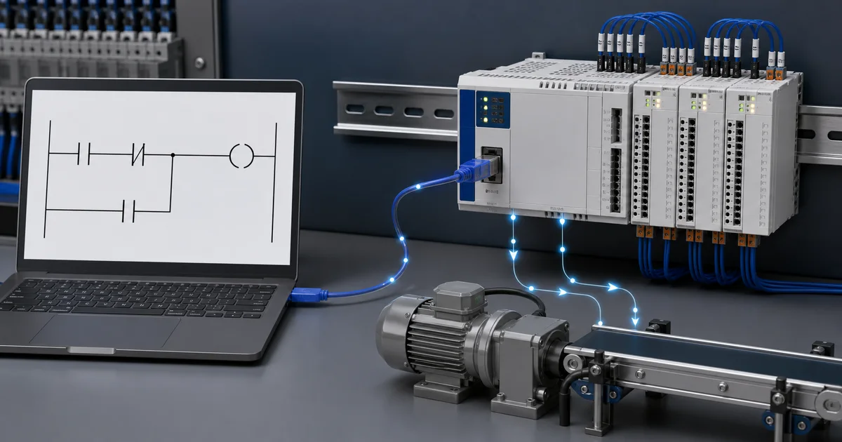
Your First Program — Motor Start/Stop with Seal-In (DVP Ladder)
This is the classic first program for any PLC: a motor start/stop circuit with a seal-in (latching) contact. It teaches the fundamental self-holding pattern used in virtually every real machine program.
What the Circuit Does
- Pressing the Start button (X0) turns the motor output (Y0) on.
- The motor stays on even after releasing Start — this is the seal-in.
- Pressing the Stop button (X1) turns the motor off.
- The circuit uses a normally closed (NC) Stop contact so the motor de-energizes if the Stop wiring breaks — the safe default.
The Ladder Rungs
Rung 1 — Start, seal-in, and Stop:
|--[ X0 ]--+--( Y0 )--|
           |
|--[ Y0 ]--+          |
|                      |
|--[/X1 ]-------------|
In Delta instruction list notation:
LD   X0       ; Load Start button (normally open)
OR   Y0       ; Parallel branch — seal-in with own output
ANI  X1       ; AND NOT Stop button (normally closed contact)
OUT  Y0       ; Energize motor output
How it works step by step:
- At rest: X0 is open, Y0 is off, X1 NC contact is closed (passing).
- Operator presses Start (X0 closes): current flows through X0, through the NC X1 contact, energizing Y0.
- Operator releases Start (X0 opens): Y0 seals itself in via the Y0 parallel contact — the motor keeps running.
- Operator presses Stop (X1 opens): the NC X1 contact breaks the rung, Y0 de-energizes, seal-in drops out.
- Motor is off. Pressing Start again repeats the cycle.
Rung 2 — Optional run indicator:
LD   Y0
OUT  Y1       ; Pilot light on while motor runs
Entering This in WPLSoft
- Open WPLSoft, create a new project, and select your DVP model.
- Click in the first rung of the ladder editor.
- Press F5 to insert a normally open contact, type
X0, press Enter. - Press F6 to insert a normally closed contact, type
X1, press Enter. - Press F7 to insert an output coil, type
Y0, press Enter. - To add the seal-in branch: click below the X0 contact, press F5, type
Y0. Connect it in parallel with X0 using the parallel branch tool. - Press F3 (Compile). Fix any errors.
- Go to Online > Simulation Mode to test: force X0 on and confirm Y0 turns on; release X0 and confirm Y0 stays on; force X1 off (simulating a pressed NC button) and confirm Y0 turns off.
Delta PLC Pricing: Build a Current BOM
Delta does not publish one global, stable family price on the product pages used for this review. Obtain dated distributor quotes for the exact CPU, I/O, power supply, network modules, cable, HMI, safety components and spares. Do not compare a bare Delta CPU with a complete competitor rack or reuse an online price without its date, region and part number.
Delta's FAQ says WPLSoft can be downloaded without purchasing the software. Treat other editor packages, add-ons, support and future terms as items to verify in the current Download Center rather than assuming every Delta software component is universally licence-free.
Ladder Logic Programming on Delta PLCs
The examples below use common DVP-style notation to explain the logic pattern. Treat timer bases, counter ranges, special relays/registers, high-speed channels and motion instructions as model-specific until the selected CPU manual confirms them.
Delta Ladder Logic Instruction Set
Basic Instruction Categories:
1. Bit Logic Instructions:
- LD (Load): Start new rung with normally open contact
- LDI (Load Inverse): Start new rung with normally closed contact
- AND: Series connection of normally open contact
- ANI (AND Inverse): Series connection of normally closed contact
- OR: Parallel connection of normally open contact
- ORI (OR Inverse): Parallel connection of normally closed contact
- OUT: Energize output coil or relay
2. Application Instructions: Comprehensive instruction set covering data movement, arithmetic operations, comparison, conversion, and specialized functions:
- MOV/DMOV: Move 16-bit or 32-bit data
- ADD/SUB/MUL/DIV: Arithmetic operations
- INC/DEC: Increment and decrement
- AND/OR/XOR: Logical operations
- CMP/ZCP: Comparison operations
- BIN/BCD: Number system conversion
- ROL/ROR: Bit rotation operations
Timer Instructions (TMR, TMRH, TTM)
TMR - General Purpose Timer: The TMR instruction provides basic timer functionality with 100ms time base, suitable for most timing applications.
Syntax:
TMR [Timer Number] [Preset Value]
Example - 5 Second Timer:
|--[ X0 ]--[TMR T0 K50]--|     Timer T0, preset 50 x 100ms = 5 sec
|
|--[ T0 ]---( Y0 )-------|     Output Y0 turns ON after 5 seconds
Parameters:
- Timer Number: T0-T255
- Preset Value: K0-K32767 (number of 100ms intervals)
- Time Range: 0.1 to 3276.7 seconds
TMRH - High-Speed Timer: TMRH provides 10ms time base for precise timing requirements, offering 10x resolution compared to standard TMR instruction.
Example - 500ms High-Speed Timer:
|--[ X1 ]--[TMRH T100 K50]--|  Timer T100, preset 50 x 10ms = 500ms
|
|--[ T100 ]---( Y1 )---------|  Precise 500ms output control
TTM - Totalizing Timer: TTM accumulates elapsed time across multiple start/stop cycles, useful for tracking total equipment run time or process duration.
Example - Totalizing Timer:
|--[ X2 ]--[TTM T200 K1000]--|  Accumulate to 1000 seconds total
|
|--[ X3 ]--[RST T200]---------|  Reset totalizer when needed
|
|--[ T200 ]---( Y2 )----------|  Output when total time reached
Counter Instructions (CNT, DCNT, DCNTR)
CNT - 16-Bit Up Counter: Basic counter instruction counts input transitions, suitable for event counting, part tracking, and batch counting applications.
Example - Count 100 Parts:
|--[ X4 ]--[CNT C0 K100]--|    Count to 100
|
|--[ X5 ]--[RST C0]-------|    Reset counter
|
|--[ C0 ]---( Y3 )--------|    Batch complete output
Counter Operation:
- Increments on rising edge (OFF to ON transition) of input X4
- Done bit (C0) activates when count reaches preset (K100)
- Reset input (X5) clears counter value to zero
- Counter value retained through power cycles
DCNT - 32-Bit Up/Down Counter: Advanced counter with up/down capability and 32-bit range, suitable for bidirectional counting applications.
DCNTR - High-Speed Counter: Dedicated high-speed counters (C235-C255) for counting high-frequency pulse inputs up to 100 kHz (DVP-ES/EX) or 200 kHz (DVP-SE/SV), essential for encoder feedback and high-speed event detection.
Complete Example: Simple Packaging Machine Control
Application Description: Automated packaging machine that fills boxes with 10 products each, then signals for box change. Includes start/stop control, emergency stop, and cycle counter.
I/O Assignment:
Inputs:
X0 - Start button (NO pushbutton)
X1 - Stop button (NC pushbutton)
X2 - Emergency stop (NC)
X3 - Product sensor (photoelectric)
X4 - Box in position sensor
X5 - Reset counter button

Outputs:
Y0 - System running indicator
Y1 - Conveyor motor
Y2 - Box full indicator
Y3 - Buzzer (box change required)
Complete Ladder Logic Program:
|--[ X2 ]--+--[ X0 ]--[ M100 ]---( M100 )--|  Rung 0: Start/Stop with seal-in
           |     |                           M100 = System run
           +--[ X1 ]----------------------|

|--[ M100 ]--[ X4 ]--( Y0 )---------------|  Rung 1: Running indicator
                                             Y0 ON when running and box present

|--[ M100 ]--[ X4 ]--( Y1 )---------------|  Rung 2: Conveyor motor
                                             Run conveyor when system active

|--[ X3 ]--[ M100 ]--[CNT C0 K10]---------|  Rung 3: Count products
                                             Count sensor pulses to 10

|--[ C0 ]---( Y2 )------------------------|  Rung 4: Box full indicator
                                             Indicate when count reaches 10

|--[ C0 ]---[TMR T0 K30]------------------|  Rung 5: Buzzer timer
                                             3 second buzzer delay

|--[ T0 ]---( Y3 )------------------------|  Rung 6: Buzzer output
                                             Sound buzzer after delay

|--[ X5 ]---[RST C0]----------------------|  Rung 7: Reset counter
|                                             Operator resets for new box
|--[ X5 ]---[RST T0]----------------------|  Rung 8: Reset timer
Program Operation:
- Operator presses Start button (X0) with box in position (X4)
- System run bit (M100) latches ON, starting conveyor motor (Y1)
- Products pass sensor (X3), counter C0 increments each detection
- When 10 products counted, box full indicator (Y2) illuminates
- Timer T0 starts, providing 3-second delay
- Buzzer (Y3) sounds after timer expires, signaling operator
- Operator removes full box, places empty box, presses reset (X5)
- Counter and timer reset, cycle repeats automatically
- Stop button (X1) or E-stop (X2) halts system anytime
Device Addressing: X, Y, M, S, T, C, D
Complete Delta PLC Address Map:
X - Input Relays (Octal Addressing):
- Range: X0-X377 (octal)
- Type: Physical digital inputs
- Configuration: NO or NC based on wiring
- Usage: Sensors, buttons, switches, discrete inputs
- Note: Uses octal numbering (0-7), X10 follows X7
Y - Output Relays (Octal Addressing):
- Range: Y0-Y377 (octal)
- Type: Physical digital outputs
- Configuration: Relay, transistor, or triac based on PLC model
- Usage: Motors, solenoids, indicators, discrete outputs
- Note: Uses octal numbering (0-7), Y10 follows Y7
M - Auxiliary Relays (Internal Memory):
- Range: M0-M4095
- Type: Internal bits (no physical I/O)
- Retention: M512-M999 retains state on power loss
- Usage: Intermediate logic, flags, state tracking
- Special: M1000-M1999 reserved for special functions
S - Step Relays (Sequential Control):
- Range: S0-S1023
- Type: State bits for sequential programming
- Usage: SFC programming, sequential state machines
- Retention: S512-S1023 retains state on power loss
T - Timers:
- Range: T0-T255
- Type: 16-bit timers with 10ms or 100ms time base
- Retention: T200-T255 retains accumulated value
- Usage: Time delays, timing control sequences
C - Counters:
- Range: C0-C255
- C0-C199: General 16-bit counters
- C200-C234: 32-bit counters
- C235-C255: High-speed counters (hardware)
- Retention: All counters retain count value
- Usage: Event counting, batch counting, position tracking
D - Data Registers:
- Range: D0-D9999
- Type: 16-bit data storage
- Retention: D200-D999 retains data on power loss
- Usage: Setpoints, parameters, calculated values, HMI interface
- Special: D1000-D1999 reserved for special functions
Special Registers and Flags
Common Special M Flags:
- M1000: RUN monitor (ON when PLC in RUN mode)
- M1001: RUN monitor (OFF when PLC in RUN mode)
- M1002: Initial pulse (ON for one scan on power-up)
- M1003: One second clock pulse (50% duty cycle)
- M1004: One minute clock pulse
- M1013: Second negative pulse (OFF for one scan per second)
- M1020: Zero flag (arithmetic result = 0)
- M1021: Borrow flag (arithmetic underflow)
- M1022: Carry flag (arithmetic overflow)
Common Special D Registers:
- D1000: PLC scan time (ms)
- D1001: Maximum scan time (ms)
- D1002: Communication watchdog time
- D1120-D1135: RTC data (year, month, day, hour, minute, second)
- D1140-D1143: High-speed counter preset values
Using Special Registers:
|--[ M1002 ]--[MOV K100 D0]--|  Initialize D0 to 100 on power-up
|
|--[ M1003 ]--[ C0 ]--( Y10)--|  Flash output at 1Hz when counter done
Motion Control and Positioning on Delta PLCs
High-Speed Pulse Output for Servo/Stepper Control
Pulse Output Capabilities: Delta DVP PLCs feature dedicated high-speed pulse outputs for controlling servo motors and stepper motor drives:
DVP-ES/EX Series:
- 2 pulse outputs (Y0, Y1 typically)
- Maximum frequency: 100 kHz
- Output types: Pulse/Direction or CW/CCW
- Resolution: 1 pulse minimum
DVP-SE/SV/SA Series:
- 4 pulse outputs (Y0, Y1, Y2, Y3 typically)
- Maximum frequency: 200 kHz
- Enhanced positioning instructions
- Linear and circular interpolation support
Pulse Output Wiring: Connect PLC pulse outputs to stepper drive or servo drive pulse input terminals according to manufacturer wiring diagrams, ensuring proper signal levels and common ground connections.
DDRVI, DDRVA, DPLSY Instructions
DDRVI - Relative Position Drive: Moves motor a specified distance (pulses) from current position at specified speed.
Syntax:
DDRVI [Pulse Output] [Number of Pulses] [Frequency]
Example - Move 10,000 Pulses at 50 kHz:
|--[ X0 ]--[DDRVI Y0 K10000 K50000]--|
           Output  Distance  Speed
           Y0      10,000    50 kHz
Application: Incremental positioning applications where movement distance relative to current position is specified, such as indexing tables, pick-and-place operations, and conveyor positioning.
DDRVA - Absolute Position Drive: Moves motor to specified absolute position at specified speed, automatically calculating required distance and direction.
Syntax:
DDRVA [Pulse Output] [Target Position] [Frequency]
Example - Move to Position 50,000:
|--[ X1 ]--[DDRVA Y0 D100 K50000]--|
           Output  Target   Speed
           Y0      D100     50 kHz
Application: Absolute positioning applications where target position is known, such as multi-position indexing, automated assembly, and coordinate-based positioning systems.
DPLSY - Variable Speed Pulse Output: Generates continuous pulse train at specified frequency, useful for variable speed control and continuous rotation applications.
Syntax:
DPLSY [Pulse Output] [Frequency] [Total Pulses]
Example - Continuous Rotation at 20 kHz:
|--[ X2 ]--[DPLSY Y0 K20000 K0]--|
           Output  Speed   Continuous
           Y0      20 kHz  (K0 = infinite)
Example: 2-Axis Positioning System
Application: X-Y Pick and Place System
System Description: Two-axis gantry system with stepper motors positioned using absolute positioning. System picks parts from input location and places in output location.
Hardware Configuration:
- X-axis: Stepper motor on Y0 output, 400 steps/rev, 5mm pitch ballscrew
- Y-axis: Stepper motor on Y1 output, 400 steps/rev, 5mm pitch ballscrew
- Home sensors: X10 (X-axis), X11 (Y-axis)
- Part present sensor: X12
- Vacuum pickup: Y10
Position Calculations:
- Steps per mm = 400 steps/rev ÷ 5mm/rev = 80 steps/mm
- Input position: X=100mm (8,000 steps), Y=50mm (4,000 steps)
- Output position: X=200mm (16,000 steps), Y=150mm (12,000 steps)
Complete Program:
|--[ M1002 ]--[MOV K0 D0]--[MOV K0 D10]--|  Rung 0: Initialize positions
             X position   Y position

|--[ X0 ]--[ M20 ]--( M20 )--------------|  Rung 1: Auto cycle start
           Auto run

|--[ M20 ]/[M21]--[SET M21]--------------|  Rung 2: Start homing sequence
|
|--[ M21 ]--[DDRVI Y0 K-50000 K10000]---|  Rung 3: Home X-axis (move negative)
|
|--[ M21 ]--[DDRVI Y1 K-50000 K10000]---|  Rung 4: Home Y-axis (move negative)
|
|--[ X10 ]--[ M21 ]--[MOV K0 D0]---------|  Rung 5: Zero X position at home
|
|--[ X11 ]--[ M21 ]--[MOV K0 D10]--------|  Rung 6: Zero Y position at home
|
|--[ X10 ]--[ X11 ]--[ M21 ]--[RST M21]--|  Rung 7: Homing complete
                               [SET M22]

|--[ M22 ]/[M23]--[DDRVA Y0 K8000 K20000]---|   Rung 8: Move to input X
|
|--[ M22 ]/[M23]--[DDRVA Y1 K4000 K20000]---|   Rung 9: Move to input Y
|
|--[ M1030 ]--[ M22 ]--[SET M23]-------------|  Rung 10: Position reached
                                                 (M1030 = pulse complete flag)

|--[ M23 ]--[TMR T0 K5]-------------------|  Rung 11: Settle delay 0.5s
|
|--[ T0 ]--[ X12 ]--[SET Y10]--------------|  Rung 12: Activate vacuum if part present
|
|--[ Y10 ]--[TMR T1 K10]-------------------|  Rung 13: Vacuum delay 1.0s
|
|--[ T1 ]--[RST M23]--[SET M24]------------|  Rung 14: Start move to output

|--[ M24 ]/[M25]--[DDRVA Y0 K16000 K20000]--|  Rung 15: Move to output X
|
|--[ M24 ]/[M25]--[DDRVA Y1 K12000 K20000]--|  Rung 16: Move to output Y
|
|--[ M1030 ]--[ M24 ]--[SET M25]------------|  Rung 17: Output position reached

|--[ M25 ]--[TMR T2 K5]-------------------|  Rung 18: Settle delay
|
|--[ T2 ]--[RST Y10]--[TMR T3 K10]--------|  Rung 19: Release vacuum, delay
|
|--[ T3 ]--[RST M25]--[RST M20]-----------|  Rung 20: Cycle complete, ready for next
Using DVP-10MC Motion Control Module
Advanced Motion Capabilities: The DVP-10MC is a dedicated 4-axis motion control module providing enhanced positioning capabilities beyond built-in PLC pulse outputs.
Key Features:
- 4 independent axes with synchronized motion
- Linear and circular interpolation (2D and 3D)
- Electronic cam profiles for complex motions
- Position compare and registration
- Flying shear and cut-to-length applications
- Servo parameter auto-tuning
- Position feedback via encoder inputs
Programming Interface: Motion control modules are programmed using specialized function blocks accessed through standard PLC ladder logic, with parameters configured in dedicated module settings.
Typical Applications:
- Multi-axis CNC-style machines
- Coordinated robotic motion
- Label registration and printing
- Flying cutoff and packaging
- Electronic gearing applications
PID Control Capabilities
PID Loop Instruction: Delta PLCs include PID (Proportional-Integral-Derivative) control functionality for closed-loop process control applications.
PID Function Block:
|--[ X0 ]--[PID S1 S2 S3 D]--|
           PV  SP  Parameters  Output
Parameters:
- S1: Process Variable (current temperature, pressure, etc.)
- S2: Setpoint (desired value)
- S3: PID parameters (Kp, Ki, Kd, sample time)
- D: Output value (control signal to valve, heater, etc.)
Example - Temperature Control:
|--[ M100 ]--[PID D100 D200 D300 D400]--|
            Current  Setpoint  PID Params  Output
            Temp     Temp      Settings    to Heater
|
|--[ M100 ]--[MOV D400 D4010]------------|  Scale output to analog module
PID Tuning: Configure PID parameters in D300+ registers:
- Proportional gain (Kp)
- Integral time (Ki)
- Derivative time (Kd)
- Sample time
- Output limits
Communication Protocols on Delta PLCs
Native Modbus RTU/ASCII Support
Model-specific Modbus communication: Many DVP, AS and AH controllers provide serial communications that can be configured for Modbus RTU. Confirm the physical port, supported master/slave role, instructions and register mapping for the exact CPU.
The following instruction and special-register fragments illustrate the shape of a Delta Modbus project. They are not a drop-in configuration for every CPU. Copy the addresses and parameters from the selected controller's current communication manual and test timeout/fault behaviour offline.
Modbus Master Configuration: Delta PLCs can function as Modbus master, polling slave devices and reading/writing data:
MODRW Instruction - Read/Write Registers:
|--[ X0 ]--[MODRW H1 H3 H1 K100 K10 D100]--|
           Port Function Slave Start  Qty  Dest
           RS485 Read(03) Addr:1 100  10regs D100
Parameters:
- H1: Communication port (H1=COM2 RS-485)
- H3: Function code 03 (Read Holding Registers)
- H1: Slave station address (1)
- K100: Starting register address (40100 in 1-based)
- K10: Quantity of registers to read (10)
- D100: Destination in PLC (data stored D100-D109)
Modbus Slave Configuration: Configure Delta PLC as Modbus slave allowing HMI or SCADA to read/write PLC data:
Settings:
- Configure COM port parameters via special D registers
- Set station address (1-247) in D1038
- Set communication format in D1036 (baud, parity, stop bits)
- Enable Modbus slave protocol
- Map PLC devices to Modbus address space
Modbus Address Mapping:
- Coils (00001-09999): Map to M relays
- Discrete Inputs (10001-19999): Map to X inputs
- Input Registers (30001-39999): Map to D registers
- Holding Registers (40001-49999): Map to D registers
Modbus TCP/IP for Ethernet Communication
Ethernet Modbus Support: Selected Delta PLCs with Ethernet interfaces support Modbus TCP. Check the exact model page for server/client roles, connection count and configuration method.
Advantages Over Serial Modbus:
- Higher speed communication (10/100 Mbps vs 115.2 kbps max)
- Longer distance capability through network switches
- Multiple simultaneous connections (8+ clients)
- Standard Ethernet infrastructure
- IT network integration
Configuration Example:
- Set PLC IP address in D1308-D1311 registers
- Configure subnet mask and gateway
- Enable Modbus TCP server function
- Configure security settings if required
- Test connection using Modbus Poll or similar tool
MODRD/MODWR Instructions: Read and write Modbus data over Ethernet connection using dedicated Modbus TCP instructions similar to serial Modbus commands.
CANopen Support on Advanced Models
CANopen Network Capability: Selected Delta CPUs or communications/motion modules support CANopen. For example, Delta's current AS product page lists CANopen motion capabilities, but the available role and axis count depend on the CPU/module.
CANopen Advantages:
- Standardized industrial communication
- Multi-master capability
- Flexible network topology
- Cost-effective cabling (twisted pair)
- Wide device support (I/O modules, drives, sensors)
Typical Applications:
- Distributed I/O expansion
- Servo drive networks
- Sensor integration
- Multi-axis motion systems
- Building automation
Delta Proprietary Protocols (DVPLINK)
DVPLINK Multi-Drop Network: Delta documents a PLC Link function for selected DVP PLCs. Station limits, ports and data areas depend on the CPU and communication mode; use the current application note rather than assuming one universal eight-slave limit.
Network Configuration:
- Master PLC initiates all communication
- Slave PLCs respond to master queries
- Shared memory area for data exchange
- Automatic data synchronization
- RS-485 based physical connection
Applications:
- Multi-machine coordination
- Distributed control systems
- Production line synchronization
- Large-scale automation projects
Communication with HMI and SCADA Systems
Delta HMI Integration: Delta DOP series HMIs connect seamlessly to Delta PLCs via:
- RS-485 serial communication (native Delta protocol)
- Ethernet TCP/IP connection
- USB programming port
- Direct device addressing (no gateway required)
Configuration Steps:
- Select Delta DVP/AH PLC in HMI project settings
- Configure communication port and parameters
- Set PLC station address
- Create HMI screens with device tags
- Map HMI objects to PLC addresses (X, Y, M, D)
- Download HMI project and test communication
Third-Party SCADA Integration: Delta PLCs integrate with popular SCADA packages using:
- Modbus RTU/TCP drivers (most common)
- OPC UA server functionality (AH/AS series)
- Proprietary drivers (if available)
- Ethernet/IP on select models
Common SCADA Systems:
- Wonderware InTouch (Modbus TCP driver)
- Ignition SCADA (Modbus driver)
- Siemens WinCC (Modbus driver)
- Any system with Modbus support
For comprehensive protocol information, see our Industrial Communication Protocols Guide.
Practical Application Example: Automated Sorting System
System Description and Requirements
Application Overview: Automated sorting system that separates products into three categories (A, B, Reject) based on size measurements from an ultrasonic sensor. System includes conveyor control, part detection, measurement, and pneumatic diverter gates.
System Requirements:
- Continuously run conveyor with variable speed control
- Detect parts on conveyor with photoelectric sensor
- Measure part height with ultrasonic analog sensor
- Divert parts into three categories based on height:
- Category A: Height > 150mm
- Category B: Height 100-150mm
- Reject: Height < 100mm
- Track counts for each category
- Emergency stop capability
- Operator interface via HMI
Hardware Components:
- Delta DVP-20SX PLC (12 inputs, 8 outputs)
- Delta DVP04AD-E 4-channel analog input module
- Photoelectric sensor (part detection)
- Ultrasonic distance sensor 4-20mA output
- Variable frequency drive (conveyor motor)
- Three pneumatic diverters with solenoid valves
- Emergency stop button
- Start/Stop control buttons
- Delta DOP-107BV 7" HMI touchscreen
Hardware Configuration (DVP-20SX with Expansion Modules)
Main PLC Unit - DVP-20SX:
- CPU: DVP-20SX (12 DI, 8 DO, 2 analog inputs built-in)
- Power Supply: 24VDC, 1.5A power consumption
- Programming Port: RS-232 (COM1)
- Communication Port: RS-485 (COM2) for HMI
Expansion Module:
- DVP04AD-E: 4-channel 12-bit analog input module
- Resolution: 12-bit (4096 counts)
- Input Range: 4-20mA, 0-10V selectable per channel
- Data Registers: D1000-D1003 (CH0-CH3)
Module Installation:
- Power OFF main PLC unit
- Connect DVP04AD-E to right side expansion connector
- Secure with mounting screws
- Configure module type in PLC program (automatic detection)
- Power ON and verify module LED indicators
I/O Mapping and Addressing
Digital Input Assignment:
X0 - Start Button (Normally Open pushbutton)
X1 - Stop Button (Normally Closed pushbutton)
X2 - Emergency Stop (Normally Closed)
X3 - Part Detection Sensor (Photoelectric, NO)
X4 - Category A Gate Position Sensor
X5 - Category B Gate Position Sensor
X6 - Reject Gate Position Sensor
X7 - Conveyor VFD Ready Signal
Digital Output Assignment:
Y0 - System Running Indicator (Green Light)
Y1 - Conveyor VFD Run Command
Y2 - Category A Diverter Solenoid
Y3 - Category B Diverter Solenoid
Y4 - Reject Diverter Solenoid
Y5 - Fault Indicator (Red Light)
Analog Input Assignment:
D1000 - Ultrasonic Height Sensor (CH0 of DVP04AD-E)
        4mA = 0mm, 20mA = 200mm
        Scaling: Height(mm) = D1000 * 200 / 4095
Internal Memory Assignment:
M0 - System Enable (Start/Stop control)
M1 - Part Detected Edge Trigger
M2 - Measurement In Progress
M3 - Category A Detected
M4 - Category B Detected
M5 - Reject Detected

D0 - Measured Height Value (mm)
D10 - Category A Count
D11 - Category B Count
D12 - Reject Count
D20 - Height Setpoint A/B Boundary (150mm)
D21 - Height Setpoint B/Reject Boundary (100mm)
Full Program with Sensor Inputs and Control Logic
Complete Ladder Logic Program:
|--[ X2 ]--+--[ X0 ]--[ M0 ]--( M0 )-----|  Rung 0: Start/Stop with seal-in
           |                                 E-stop, Start, Stop control
           +--[ X1 ]---------------------|

|--[ M0 ]--( Y0 )------------------------|  Rung 1: Running indicator
                                            Green light when system active

|--[ M0 ]--[ X7 ]--( Y1 )----------------|  Rung 2: Conveyor motor
                                            Run when system enabled and VFD ready

|--[ X3 ]/[ M1 ]--[SET M1]---------------|  Rung 3: Part detection edge detect
|
|--[ M1 ]--[TMR T0 K2]-------------------|  Rung 4: Debounce timer 200ms
|
|--[ T0 ]--[SET M2]--[RST M1]------------|  Rung 5: Start measurement

|--[ M2 ]--[MOV D1000 D100]--------------|  Rung 6: Read analog input
                                            Copy raw ADC value

|--[ M2 ]--[MUL D100 K200 D102]----------|  Rung 7: Scale calculation
|                                           Multiply by 200 (max height)
|--[ M2 ]--[DIV D102 K4095 D0]-----------|  Rung 8: Complete scaling
                                            Divide by 4095 = height in mm

|--[ M2 ]--[CMP D0 D20 M10 M11 M12]------|  Rung 9: Compare to setpoint 150mm
                                            M10=greater, M11=equal, M12=less

|--[ M10 ]--[ M2 ]--[SET M3]-------------|  Rung 10: Category A (>150mm)
|
|--[ M12 ]--[ M2 ]--[CMP D0 D21 M13 M14 M15]--|  Rung 11: Compare to 100mm
|
|--[ M13 ]--[ M2 ]--[SET M4]-------------|  Rung 12: Category B (100-150mm)
|
|--[ M15 ]--[ M2 ]--[SET M5]-------------|  Rung 13: Reject (<100mm)

|--[ M3 ]--[TMR T10 K5]------------------|  Rung 14: Diverter timing
|                                           Wait for part to reach gate
|--[ T10 ]--[TMR T11 K3]--(Y2)-----------|  Rung 15: Category A diverter ON
|                                           300ms pulse to diverter
|--[ T11 ]--[INC D10]--[RST M2]----------|  Rung 16: Increment count, reset
           [RST M3]

|--[ M4 ]--[TMR T20 K8]------------------|  Rung 17: Category B timing
|
|--[ T20 ]--[TMR T21 K3]--(Y3)-----------|  Rung 18: Category B diverter ON
|
|--[ T21 ]--[INC D11]--[RST M2]----------|  Rung 19: Increment count B
           [RST M4]

|--[ M5 ]--[TMR T30 K12]-----------------|  Rung 20: Reject timing
|
|--[ T30 ]--[TMR T31 K3]--(Y4)-----------|  Rung 21: Reject diverter ON
|
|--[ T31 ]--[INC D12]--[RST M2]----------|  Rung 22: Increment count Reject
           [RST M5]

|--[ X4 ]/[ Y2 ]--[SET M20]--------------|  Rung 23: Gate A fault detection
|
|--[ X5 ]/[ Y3 ]--[SET M21]--------------|  Rung 24: Gate B fault detection
|
|--[ X6 ]/[ Y4 ]--[SET M22]--------------|  Rung 25: Reject gate fault

|--[ M20 ]--+--[ M21 ]--+--[ M22 ]--( Y5 )--|  Rung 26: Fault indicator
           |            |                      Any gate fault = red light
           +------------+

|--[ M1002 ]--[MOV K150 D20]-------------|  Rung 27: Initialize setpoints
            [MOV K100 D21]                  On power-up, load default values
Program Features:
- Start/Stop control with emergency stop
- Part detection with debounce filtering
- Analog measurement with proper scaling
- Multi-level comparison for three categories
- Precise timing for diverter activation
- Count tracking for each category
- Fault detection and indication
- Automatic initialization on power-up
Conveyor Control and Sorting Logic
Conveyor Speed Control: For variable speed control, add analog output module (DVP02DA) to provide 0-10V signal to VFD:
|--[ M0 ]--[MOV D50 D4000]---------------|  Control speed via D50 setpoint
                                           D4000 = Analog output Ch0
                                           0-1000 = 0-10V to VFD
Speed Adjustment Example:
- D50 = 500 (50% speed, 5V output, ~30 ft/min)
- D50 = 750 (75% speed, 7.5V output, ~45 ft/min)
- D50 = 1000 (100% speed, 10V output, ~60 ft/min)
Sorting Logic Timing: Critical timing ensures parts reach correct diverter gates:
- Part detected at sensor (X3)
- Measurement taken and category determined
- Timer calculates delay based on:
- Conveyor speed
- Distance from sensor to gate
- Part size compensation
- Diverter activated with short pulse (300ms)
- Part diverted into chute
- Gate returns to normal position
Timing Calculations:
Delay Time = (Distance to Gate / Conveyor Speed) + Safety Margin

Category A: 500mm distance, 500mm/s speed = 1.0s + 0.2s = T10 K12
Category B: 800mm distance, 500mm/s speed = 1.6s + 0.2s = T20 K18
Reject: 1200mm distance, 500mm/s speed = 2.4s + 0.2s = T30 K26
Integration with Delta DOP HMI
HMI Screen Design:
Main Screen Elements:
- Start/Stop buttons mapped to M0 (toggle bit)
- Emergency stop indicator showing X2 status
- Conveyor running indicator showing Y1 status
- Real-time height display showing D0 value
- Category counts displaying D10, D11, D12
- Speed setpoint adjustment for D50
- Reset counters button
- Fault status display showing Y5
HMI Configuration Steps:
- Create new project in DOPSoft software
- Select DOP-107BV 7" model
- Configure PLC communication:
- PLC Type: Delta DVP
- Interface: RS-485 (COM2)
- Baud Rate: 19200
- Station: 1
- Design main screen with objects
- Map each object to PLC addresses
- Add trend chart for D0 (height measurements)
- Create alarm screen for fault conditions
- Download project to HMI via USB
- Test communication and operation
HMI Address Mapping Example:
Object Type     | Function        | Address | Format
Button (Toggle) | Start/Stop      | M0      | Bit
Indicator       | Running         | Y0      | Bit
Numeric Display | Height          | D0      | Word (0-200)
Numeric Display | Count A         | D10     | Word (0-9999)
Numeric Display | Count B         | D11     | Word (0-9999)
Numeric Display | Count Reject    | D12     | Word (0-9999)
Numeric Input   | Speed Setpoint  | D50     | Word (0-1000)
Button (Mom.)   | Reset Counts    | M100    | Bit
Indicator       | Fault           | Y5      | Bit
Advanced HMI Features:
- Recipe management storing setpoints (D20, D21) for different products
- Trend chart displaying height measurements over time
- Data logging to SD card for quality records
- Alarm history showing fault events with timestamps
- Password protection for setpoint modifications
- Production reports with daily/weekly totals
Delta PLC Programming Best Practices
Program Organization and Structure
Main Program Structure: Organize programs into logical sections using comments and structured layout:
|===========================================================|
|  SECTION 1: INITIALIZATION                               |
|  Power-up initialization, default values, system setup   |
|===========================================================|

|--[ M1002 ]--[MOV K100 D0]--|  Initialize setpoints
            [MOV K0 C0]        Reset counters

|===========================================================|
|  SECTION 2: INPUTS AND EDGE DETECTION                    |
|  Input conditioning, debouncing, edge triggers           |
|===========================================================|

|===========================================================|
|  SECTION 3: MAIN CONTROL LOGIC                           |
|  Primary control sequences and logic                     |
|===========================================================|

|===========================================================|
|  SECTION 4: OUTPUTS                                      |
|  Output control and interlocks                           |
|===========================================================|

|===========================================================|
|  SECTION 5: ERROR HANDLING                               |
|  Fault detection and emergency procedures                |
|===========================================================|
Section Organization Benefits:
- Easier troubleshooting and maintenance
- Faster modification and updates
- Better documentation and understanding
- Reduced programming errors
- Team collaboration improvement
Using Subroutines for Modular Code
Subroutine Advantages:
- Code reusability across multiple locations
- Simplified main program logic
- Easier testing and debugging
- Reduced program size
- Modular functionality
Creating Subroutines in WPLSoft:
- Click Compile → Insert Program → Insert Subroutine
- Enter subroutine number (P0-P255)
- Program subroutine logic
- Return to main program automatically at end
Calling Subroutines:
|--[ X0 ]--[CALL P0]--| Call subroutine P0 when X0 is ON
Example - Analog Scaling Subroutine:
Main Program:
|--[ M100 ]--[MOV D1000 D200]--[CALL P0]--|  Read analog, call scaling
|
|--[ M100 ]--[MOV D201 D50]---------------|  Use scaled result

Subroutine P0:
|--[MUL D200 K200 D202]--|  Multiply by span
|--[DIV D202 K4095 D201]--|  Divide by ADC range = scaled value
|--[RET]--|                  Return to main program
Subroutine Best Practices:
- Document subroutine purpose and parameters
- Use consistent data register assignments
- Avoid excessive nesting (max 3-4 levels)
- Test subroutines independently
- Create library of common functions
Naming Conventions and Documentation
Device Comment System: WPLSoft includes device comment functionality allowing descriptive names for devices:
Adding Device Comments:
- Open Tools → Device Comment
- Enter device address (X0, Y0, M100, D0, etc.)
- Type descriptive comment (max 16 characters in WPLSoft)
- Comments appear in ladder editor and cross-reference
Example Device Comments:
X0 - Start_Btn
X1 - Stop_Btn
X2 - E_Stop
Y0 - Motor_Run
M100 - System_En
D0 - Speed_SP
T0 - Dly_Timer
C0 - Part_Count
Documentation Best Practices:
- Comment every input and output
- Explain complex logic rungs
- Document all setpoints and their units
- Include revision history
- Note special requirements or limitations
Program Header Documentation:
|===========================================================|
| PROJECT: Automated Sorting System                        |
| CUSTOMER: ABC Manufacturing                              |
| DATE: 2025-12-10                                         |
| PROGRAMMER: [Name]                                       |
| PLC MODEL: Delta DVP-20SX                                |
| VERSION: 1.0                                             |
| DESCRIPTION: Three-category sorting based on height      |
|===========================================================|
Backup and Version Control
Regular Backup Procedures:
- Upload complete program from PLC to computer
- Save project file with date in filename
- Create project folder structure:
Project_Name/ ├── Programs/ │ ├── 2025-12-01_v1.0.dvp │ ├── 2025-12-05_v1.1.dvp │ └── 2025-12-10_v1.2.dvp ├── Documentation/ │ ├── IO_List.xlsx │ ├── Wiring_Diagrams.pdf │ └── User_Manual.pdf └── HMI/ └── Screen_Project.dop - Maintain change log documenting modifications
- Store backups on network drive and external media
Version Control Benefits:
- Recover from programming errors
- Track changes over time
- Compare different versions
- Rollback to previous working version
- Document system evolution
Change Documentation Template:
Version 1.2 - 2025-12-10
- Added Category C sorting logic
- Modified timer values for faster sorting
- Fixed counter reset issue
- Updated HMI screens with new category
Using Simulation Mode Effectively
Simulation Testing Strategy:
Phase 1 - Basic Logic Verification:
- Load program in simulation mode
- Manually set inputs to test each rung
- Verify outputs respond correctly
- Check timer and counter operations
- Confirm mathematical calculations
Phase 2 - Sequence Testing:
- Create test scenarios simulating real operation
- Step through complete machine cycles
- Test all operational modes
- Verify error handling and interlocks
- Confirm data logging and communication
Phase 3 - Edge Case Testing:
- Test boundary conditions
- Simulate simultaneous inputs
- Verify timeout conditions
- Test maximum count values
- Confirm emergency stop procedures
Simulation Limitations Awareness:
- Analog inputs require manual entry
- High-speed counters may behave differently
- Communication functions limited
- Timing precision may vary
- Physical I/O interactions not simulated
Pre-Commissioning Checklist:
- All logic tested in simulation
- Device comments completed
- Documentation printed
- Backup created
- HMI screens tested
- I/O wiring verified against program
Cost-Effective System Design
Hardware Selection Strategies:
Right-Size Your PLC:
- Count actual I/O requirements (with 20% spare capacity)
- Select smallest PLC model meeting requirements
- Use expansion modules only when necessary
- Consider integrated functions (analog inputs) vs separate modules
Example System Sizing:
Requirements: 18 digital inputs, 12 digital outputs, 2 analog inputs
Option 1: DVP-32ES (16DI/16DO) + DVP04AD-E = $400 + $150 = $550
Option 2: DVP-24ES (14DI/10DO) + DVP08SN (8DI) + DVP04AD-E = $650
Best Choice: Option 1 (fewer modules, lower cost, simpler)
Standardize on Delta Ecosystem:
- Use Delta HMI for best integration (no protocol conversion)
- Select Delta VFDs for seamless communication
- Choose Delta servo/stepper for motion applications
- Leverage free software and technical support
Long-Term Cost Reduction:
- Document systems thoroughly for faster troubleshooting
- Train multiple personnel on Delta platform
- Stock common spare parts
- Build program library for reuse
- Establish relationship with Delta distributor
Total Cost of Ownership Comparison:
                    Delta DVP    Siemens S7-1200   AB Micro850
Initial Hardware    $600         $1,200           $1,100
Software            FREE         $3,500           FREE
Training            $500         $2,000           $1,500
Annual Support      $200         $800             $600
5-Year TCO          $1,600       $9,500           $4,600
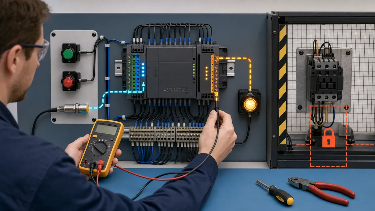
Troubleshooting Common Issues
USB Connection Problems
Problem: WPLSoft Cannot Detect PLC
Symptoms:
- Communication error messages
- "PLC not found" errors
- Timeout during upload/download
Diagnostic Steps:
- Verify USB cable connection (both ends)
- Check PLC power LED indicator (should be solid ON)
- Confirm correct COM port selected in WPLSoft
- Verify USB driver installation (Device Manager)
- Try different USB cable
- Test different computer USB port
Solutions:
- Install Delta USB driver from download center
- Select correct COM port (Tools → Communication Setting)
- Reduce baud rate to 9600 for reliability
- Disable Windows power management for USB port
- Run WPLSoft as administrator
- Restart PLC and computer
USB Driver Installation:
- Download Delta USB driver package
- Extract and run setup.exe
- Connect PLC via USB cable
- Windows detects new hardware
- Point to driver folder when prompted
- Verify "Delta PLC" appears in Device Manager
- Note assigned COM port number (COM3, COM4, etc.)
- Configure WPLSoft to use same COM port
Communication Cable Issues
RS-485 Communication Problems:
Problem: No Communication on RS-485 Network
Symptoms:
- HMI shows "Communication Error"
- Modbus timeout errors
- No data exchange between devices
Diagnostic Checks:
- Verify RS-485 wiring polarity (A to A, B to B)
- Check termination resistors (120Ω at both ends)
- Measure voltage between A and B lines (should show differential)
- Confirm matching baud rate on all devices
- Verify station addresses are unique
- Check cable shield grounding (one point only)
Common Wiring Errors:
- Reversed A and B connections
- Missing termination resistors
- Multiple ground points creating ground loops
- Exceeding maximum cable length (1200m for RS-485)
- Too many devices on network (max 32 without repeater)
- Damaged cable or loose connections
Correct RS-485 Wiring:
PLC COM2              HMI COM1
D+ (A) --------------- D+ (A)
D- (B) --------------- D- (B)
GND -------------------- GND
[120Ω]                [120Ω]  (Termination resistors at ends)
PLC Error Codes and Indicators
LED Indicator Meanings:
Power LED:
- Solid Green: Normal operation, power good
- OFF: No power supply
- Solution: Check 24VDC power supply
Run LED:
- Solid Green: PLC in RUN mode, scanning program
- Blinking Green: PLC in STOP mode
- Solution: Change to RUN mode or check for errors
Error LED:
- OFF: No errors
- Solid Red: Fatal error (syntax, hardware failure)
- Blinking Red: Warning (communication timeout, module error)
Common Error Codes:
Error 6102 - Syntax Error:
- Cause: Program contains compilation errors
- Solution: Compile program and fix reported errors, verify all instructions have proper parameters
Error 6104 - Watchdog Timeout:
- Cause: Program scan time exceeds maximum (typically 200ms)
- Solution: Simplify program logic, use subroutines, reduce complex calculations, optimize scan
Error 6201 - I/O Module Error:
- Cause: Expansion module not detected or failed
- Solution: Check module connections, power cycle PLC, verify module compatibility, replace if failed
Error 6301 - Battery Low:
- Cause: Backup battery voltage low (retentive memory at risk)
- Solution: Replace backup battery (CR2032), backup program before battery failure
Checking Error Information:
- Connect with WPLSoft in online mode
- Select Online → PLC Status Monitor
- View error code and description
- Check error history log
- Clear error after resolution (if not hardware failure)
Modbus Communication Errors
Problem: Modbus Read/Write Failures
Common Error Codes:
- Error 0: No error, successful transaction
- Error 1: Function code not supported by slave
- Error 2: Register address invalid or out of range
- Error 3: Data value invalid or out of range
- Error 4: Slave device failure or offline
- Error 8: Timeout waiting for response
Diagnostic Procedure:
- Verify physical RS-485 wiring and termination
- Confirm baud rate and communication format match all devices
- Check slave station addresses (1-247, must be unique)
- Validate Modbus register addresses (0-based vs 1-based confusion)
- Use Modbus diagnostic software (Modbus Poll) to isolate issue
- Reduce baud rate to eliminate timing issues
- Increase timeout value in MODRW instruction
Example Debug Code:
|--[ M100 ]--[MODRW H1 H3 H1 K100 K10 D100]--|  Read operation
|
|--[ M100 ]--[MOV D1167 D500]-----------------|  Copy error code to D500
|                                               (D1167 contains MODRW error code)
|--[ M100 ]--[CMP D500 K0 M200 M201 M202]----|  Compare error code
|
|--[ M202 ]--( Y10 )--------------------------|  Light indicator if error
For comprehensive Modbus troubleshooting, refer to our Modbus RTU Protocol Tutorial.
Common Programming Mistakes
Mistake 1: Octal Addressing Confusion
Problem:
|--[ X8 ]--( Y8 )--| INVALID - No X8 or Y8 in octal
Correct:
|--[ X10 ]--( Y10 )--| After X7 comes X10 (octal numbering)
Mistake 2: Missing Edge Detection
Problem:
|--[ X0 ]--[INC D0]--| Increments continuously while X0 ON
Correct:
|--[ X0 ]/[ M0 ]--[SET M0]--[INC D0]--|  Increments once per X0 transition
|--/ X0 ]--[RST M0]------------------|
Mistake 3: Incorrect Timer/Counter Reset
Problem:
|--[ X0 ]--[TMR T0 K50]--|
|--[ T0 ]--[RST T0]------|  Self-resetting creates oscillation
Correct:
|--[ X0 ]--[TMR T0 K50]--|
|--[ X1 ]--[RST T0]------|  External reset control
Mistake 4: Scan Time Dependent Logic
Problem: Assuming specific scan time for critical timing operations without verification.
Solution: Use hardware timers and counters for precise timing, not scan-dependent logic. Test actual scan time using D1000 (scan time in ms).
Mistake 5: Uninitialized Values
Problem: Using data registers without initialization can cause unpredictable behavior on first scan.
Solution:
|--[ M1002 ]--[MOV K0 D0]--|  Initialize all critical values on power-up
            [MOV K100 D10]   M1002 = first scan pulse
Frequently Asked Questions
Is Delta PLC programming software free?
Delta's official FAQ says WPLSoft can be downloaded from its website without purchasing the software. ISPSoft and DIADesigner are also distributed through Delta's Download Center. Verify the current regional terms, package dependencies, optional modules and supported controller before treating the engineering environment as a zero-cost project line item.
How does Delta PLC compare to Siemens or Allen-Bradley?
Compare exact part-number BOMs, supported instructions, safety requirements, protocols, lifecycle status, local support and engineering time. A brand-level “30–50% cheaper” claim is not reliable because regional quotes and project scope vary. The right choice is the controller that satisfies a dated functional specification with acceptable lifecycle and support risk.
For detailed comparisons, see our Siemens vs Allen-Bradley PLC Comparison guide.
What is the difference between DVP and AH series?
DVP series are compact PLCs with integrated I/O in a single housing, designed for simple to medium-complexity applications. AH series are modular PLCs intended for larger systems and advanced motion or networking requirements. DVP projects may use WPLSoft or ISPSoft depending on the exact CPU, while AH projects use ISPSoft. Confirm current I/O limits, module features, and editor compatibility for the exact part number in Delta's official catalog before specifying hardware.
Can Delta PLCs be used for motion control?
Some Delta CPUs and motion modules provide pulse, CANopen or EtherCAT motion control, but the limit is model-specific. As one current example, Delta's AS-series page states up to eight axes over CANopen motion and up to six axes using 200 kHz pulse control. The DVP-ES3 page separately lists model-dependent CANopen or EtherCAT capabilities. Verify the exact CPU, output type, bus, servo compatibility and instruction support.
What programming languages do Delta PLCs support?
DVP projects commonly use Ladder Diagram through WPLSoft, ISPSoft or DIADesigner, depending on the CPU. ISPSoft can provide LD, FBD, ST, SFC and legacy IL workflows, while Delta's current catalogue notes that supported languages differ by PLC series. Check the current CPU/software matrix before choosing an editor.
How reliable are Delta PLCs?
Reliability depends on the exact controller, environment, electrical design, and maintenance. Use the model-specific datasheet for temperature, vibration, EMC, approvals, and any published reliability figures; do not apply a family-level MTBF claim to every Delta PLC. Correct enclosure design, power quality, grounding, surge protection, and preventive maintenance are as important as the controller choice.
What industries use Delta PLCs?
Delta's current product pages name applications including packaging, electronics manufacturing, labelling, food machinery, textiles and logistics. Actual suitability depends on the selected controller, required certifications, environmental ratings, safety architecture and local support.
Can Delta PLCs communicate via Modbus?
Many Delta PLCs support Modbus RTU or Modbus TCP, but port availability, master/slave roles and instructions vary by model. Confirm the exact CPU manual and test the target device's function codes, register map, byte order, timeout and fault recovery. Protocol support alone does not guarantee application-level compatibility.
Is Delta PLC good for beginners?
Delta can be a useful learning platform when the CPU/editor combination matches equipment you can access. Its simulator is suitable for logic practice, but Delta explicitly warns that simulator timing and instruction support differ from hardware. Use it to learn the sequence, then validate I/O, communications, motion and timing on the actual controller.
How do I get started with Delta PLC programming?
Start by choosing an exact Delta CPU already used in your workplace or available on a training bench. Download the supported editor from Delta, archive the matching manuals, and test a motor start/stop program in simulation. Before purchasing hardware, obtain a dated BOM for the CPU, power supply, I/O, programming interface and any required communications modules. Then repeat the test on hardware with a documented I/O checkout and safe low-energy training circuit.
Conclusion: Prove the Exact Delta Configuration
The durable workflow is model-specific: identify the CPU, confirm the editor and language support, build the I/O map, simulate only supported behaviour, validate on hardware, and retain the software/manual versions with the project. That approach is more useful than family-wide price, reliability or feature claims.
The ladder, addressing, communications and troubleshooting examples in this guide provide a starting point. The selected Delta CPU and its current manuals remain authoritative for electrical limits, supported instructions, motion, protocols and lifecycle status.
Primary Sources and Verification Notes
Checked 25 July 2026:
- Delta PLC product catalogue — current families, editors and the warning that language support varies by PLC series.
- Delta DVP-ES3 product page — model-specific editor, memory, I/O, protocol and motion data.
- Delta AS-series product page and AS programming manual — AS architecture, limits, languages and software references.
- Delta FAQ: ISPSoft vs WPLSoft and software download — DVP editor scope and WPLSoft availability.
- Delta FAQ: Windows compatibility — WPLSoft and ISPSoft operating-system support.
- Delta FAQ: simulator limitations — unsupported instructions and the requirement to retest on actual hardware.
- Delta DVP PLC Link application note — model-specific serial link examples and cautions.
This site is independent of Delta Electronics. Product names identify compatibility context; the illustrations are editorial unless a caption explicitly labels a real product capture.
Next Steps in Your Automation Journey
Continue developing your PLC programming expertise through hands-on practice with Delta hardware, studying vendor documentation and application notes, building complete automation projects from specification through commissioning, and staying current with emerging technologies and protocols. The skills learned through Delta PLC programming translate directly to other platforms while providing immediate value in cost-sensitive automation markets worldwide.
Related PLC Programming Resources
Expand your industrial automation knowledge with these comprehensive guides:
- Free PLC Programming Software Guide - Download free development tools for learning
- Ladder Logic Tutorial - Master fundamental PLC programming language
- Modbus RTU Protocol Tutorial - Implement industrial communication networks
- PLC Programming for Beginners - Start your automation career
- Best PLC Programming Software 2026 - Compare all major platforms
Practise the Logic Before Hardware Checkout
Use the DVP-style start/stop and sequence examples as a specification, then recreate the same control intent in the browser PLC simulator. The simulator is for learning and logic feedback; it does not emulate a Delta CPU, replace Delta's engineering tools, or prove hardware timing, communications or safety behaviour.


