Delta PLC Modbus Address: DVP Map and Examples
Translate Delta DVP X, Y, M, T, C and D devices into Modbus function, zero-based request offset and client display notation, then prove the map safely.
Review status: Editorially reviewed against Delta's current PLC family page; official DVP-PLC Application Manual communication-address tables; current DVP starter-kit manual; official Delta Kepware, InTouch and DIAView integration manuals; Modbus Organization application and serial-line specifications; Delta product cybersecurity advisories; NIST SP 800-82 Rev. 3; and US OSHA hazardous-energy/electrical work rules. Device ranges, memory retention, special devices, port roles, serial settings, Ethernet services, station/unit behavior, supported function codes, request quantities, firmware, editor/driver notation, safety response and cybersecurity controls remain exact-CPU-, module-, firmware-, project-, client-, network-, process-, risk- and site-specific
Direct answer
A Delta PLC Modbus address is not just the number printed beside a PLC device. For a classic Delta DVP device such as D0, identify four things: the PLC device (D0), its Delta communication address (H1000), the zero-based Modbus PDU offset sent in the request (4096 decimal, bytes 10 00), and the notation expected by the client. Delta's DVP table displays D0 as 404097; a client that asks for a holding-register area plus a zero-based offset normally uses area holding register / FC03 and address 4096. A Delta-aware driver may accept D0 directly.
For the common DVP ranges, D0 through D4095 map to H1000 through H1FFF, but the next block is discontinuous: D4096 starts at H9000, not H2000. The same kind of discontinuity appears in internal relays: M0 starts at H0800, while M1536 starts at HB000. Never apply a single base + device number formula beyond the block for which Delta documents it.
Physical inputs and outputs add another trap. DVP X and Y labels use octal numbering, so X10 is the eighth point after X0, not decimal point ten. X0 maps to H0400 and is represented by Delta as discrete input 101025; Y0 maps to H0500 and is represented as coil 001281. The function/object type is part of the address. Entering the right number under the wrong function code still targets the wrong Modbus object or produces an exception.
There is no safe universal “Delta PLC address table” for every DVP, AS, AH, AX or motion CPU. Delta's current portfolio contains materially different controller families and software environments. Confirm the exact CPU ordering code, hardware/firmware, port or communication module, server/client role and its current manual. This guide uses the official DVP communication table for worked mappings and treats other families as a separate verification branch.
Use the generic Modbus registers and addressing guide for protocol-wide 0x/1x/3x/4x, zero-versus-one-based and data-model concepts. This page owns the Delta DVP translation, client-entry and proof workflow. Use the Delta PLC programming tutorial for controller/editor selection rather than expanding this address guide into a general Delta tutorial.
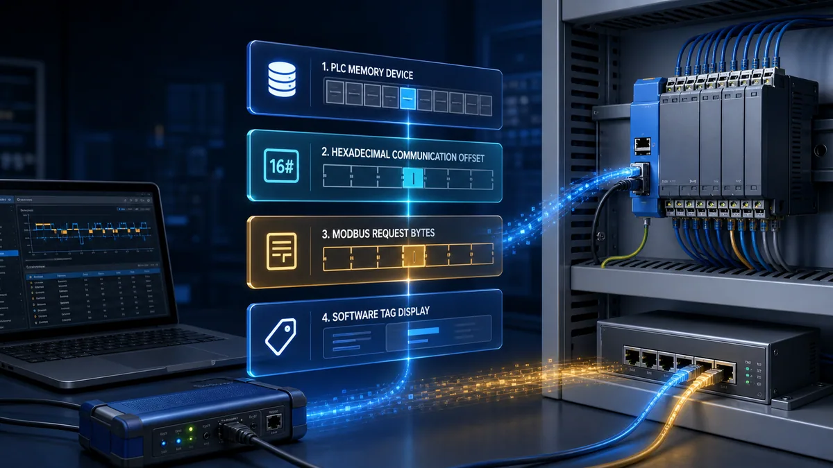
Start with the exact Delta controller and communication role
Separate DVP mapping from AS, AH, AX and motion families
Delta's current PLC page lists DVP, AS, AH and AX families with different CPU types, tools, networks and options. “Delta PLC” is therefore too broad to select an address map. Record the exact nameplate ordering code, hardware revision, firmware, editor project type and communication interface before copying any table. A DVP-SS2 serial port, a DVP-SE Ethernet CPU, an AS CPU and an Ethernet function card can expose different configuration, capacity and diagnostic behavior even when all support some form of Modbus.
The official DVP application manual contains the DVP device communication table used here. Its ranges also vary by DVP model: a mapping row can exist in the family table while a smaller CPU does not implement the entire device range. The current Delta DVP starter-kit manual demonstrates this by presenting effective ranges for the actual starter CPUs beside the communication map. Treat mapped and implemented on this CPU as separate questions.
| Evidence to freeze | Example | Why it controls the result | Acceptance evidence |
|---|---|---|---|
| CPU ordering code | Exact DVP, AS, AH or AX part number | Selects device ranges, editor, ports and manuals | Nameplate photo plus approved BOM |
| Hardware and firmware | Recorded from diagnostics/project | Features and limits may be revision-dependent | Exported device information |
| Physical interface | Built-in RS-485, Ethernet CPU or module | Selects RTU/ASCII/TCP setup and diagnostics | Port/module manual and topology |
| Protocol role | Server/device or client/controller | Determines who initiates requests and which map is exposed | Approved communication matrix |
| Engineering software | WPLSoft, ISPSoft or DIADesigner as supported | Labels and parameter workflow differ | Archived project and tool version |
| Client/driver | SCADA, HMI, gateway or test client | Controls symbolic, zero-based or reference notation | Driver name/version/config export |
| Process ownership | Read-only indication or writable command | Controls permissions, validation and fallback | Tag contract and risk review |
Distinguish server map from client polling instructions
When an HMI, SCADA, gateway or test tool reads a DVP PLC acting as a Modbus server, it targets the PLC's exposed device map. When the PLC acts as a Modbus client and polls an external drive, meter or sensor, the remote device's register map controls the request; a local D100 may merely be the destination buffer. Do not translate the external sensor's register through the Delta DVP server table.
Write one sentence for each exchange: “SCADA client reads one holding register from DVP server Unit 1 at PDU offset 0x1000 into tag LineSpeedRaw,” or “DVP client reads two input registers from meter Unit 7 at the meter vendor's offset into local D200:D201.” This single statement prevents many direction and ownership errors.
| Question | DVP used as server/device | DVP used as client/controller |
|---|---|---|
| Who starts the transaction? | External HMI/SCADA/gateway | PLC program or communication configuration |
| Whose Modbus map is addressed? | Delta DVP device map | Remote vendor's device map |
| What does local D memory mean? | Exposed PLC data register where supported | Request parameters, buffer or application storage |
| Where is function code chosen? | External client/driver | PLC instruction/configuration |
| Primary diagnostic evidence | External request plus PLC response/exception | PLC request state/status plus remote response |
| Common mistake | Entering D0 as offset zero |
Applying Delta's D0 map to a non-Delta slave |
Translate the four address representations without guessing
Keep PLC symbol, Delta hex, PDU offset and client label separate
The PLC programmer thinks in symbols such as X0, Y0, M100 and D500. Delta's DVP table assigns each implemented device a hexadecimal communication address. A Modbus request carries a function code and a zero-based address field; it does not transmit the six-digit 404097 reference label. Client software may display an extended reference, request a zero-based number under a selected object type, subtract one automatically, or provide a Delta-native symbolic driver.
Create four columns in the interface control document and never reuse one column's value in another without stating the conversion. If a tool has an “address base” setting, record it. If the driver manual calls the field “register,” determine whether it means a wire offset or a human reference. A screenshot is useful only when accompanied by driver name, version, object type and base setting.
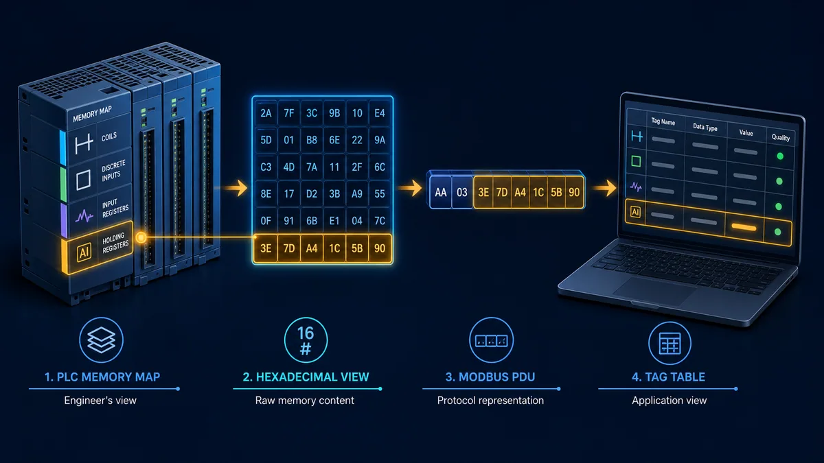
Use the function code as an address-space selector
The Modbus application specification defines distinct data objects. FC01 reads coils, FC02 reads discrete inputs, FC03 reads holding registers and FC04 reads input registers. Write functions include FC05/FC15 for coils and FC06/FC16 for holding registers. The DVP table associates X with discrete-input references, writable bit devices such as Y/M with coils, and D words with holding-register references in the documented map.
The leading 0, 1 or 4 in a human reference is not part of the PDU address field. It communicates object type to people or software. A client interface that has separate “Coils,” “Discrete Inputs” and “Holding Registers” selectors often expects only the numeric offset. A client that accepts extended references may expect Delta's six-digit form such as 404097. Verify with one known value rather than toggling random output locations.
| PLC intent | Modbus object/function | DVP example | PDU start | Delta displayed reference | Permission boundary |
|---|---|---|---|---|---|
| Read physical input | Discrete inputs / FC02 | X0 |
0x0400 / 1024 |
101025 |
Read-only process indication |
| Read physical output image | Coils / FC01 | Y0 |
0x0500 / 1280 |
001281 |
Reading does not prove load state |
| Write physical output image | Single/multiple coil / FC05 or FC15 where supported | Y0 |
0x0500 / 1280 |
001281 |
Hazardous; require authorization/interlocks |
| Read internal relay | Coils / FC01 | M0 |
0x0800 / 2048 |
002049 |
Application-defined quality/meaning |
| Read timer contact | Coils / FC01 | T0 bit |
0x0600 / 1536 |
001537 |
Boolean completion/contact state |
| Read timer current value | Holding register / FC03 | T0 word |
0x0600 / 1536 |
401537 |
Numeric word interpretation |
| Read counter value | Holding register / FC03 | C0 word |
0x0E00 / 3584 |
403585 |
Width changes for documented counter ranges |
| Read/write data word | Holding register / FC03/06/16 | D0 |
0x1000 / 4096 |
404097 |
Define read/write ownership and bounds |
The rows are DVP family mappings from the cited Delta table, not a claim that every CPU exposes every range or accepts every write/function. Confirm the exact CPU/port/manual and client driver.
Use the DVP device map block by block
Treat X, Y, M and D as different banks
X represents physical input devices and Y physical output devices in the DVP programming model; M is internal bit memory and D is word memory. The Modbus map does not erase those application meanings. A valid response from Y0 proves the PLC's mapped output image at the time of the response, not voltage at a terminal, current through a load or motion of an actuator. A valid D response proves a word was transferred, not its type, scale, quality or freshness.

The table below is intentionally a block summary, not a complete substitute for Delta's manual. It shows why casual formulas fail.
| DVP device block | Delta communication range | PDU offset behavior | Critical note |
|---|---|---|---|
S0:S1023 |
H0000:H03FF |
Four contiguous 256-bit blocks | Implemented step-relay range depends on CPU |
X0:X377 octal |
H0400:H04FF |
Linear 256-bit block | PLC label is octal; object is discrete input |
Y0:Y377 octal |
H0500:H05FF |
Linear 256-bit block | PLC label is octal; output writes are hazardous |
T0:T255 |
H0600:H06FF |
Same offsets interpreted as bit or word by function | Timer contact and current value are different objects |
M0:M1535 |
H0800:H0DFF |
Six contiguous 256-bit blocks | M1536 does not continue at H0E00 |
M1536:M4095 |
HB000:HB9FF |
Ten high-address 256-bit blocks | Large discontinuity after M1535 |
C0:C199 |
H0E00:H0EC7 |
Bit and 16-bit word forms documented | Do not assume 32-bit counter layout is identical |
D0:D4095 |
H1000:H1FFF |
Sixteen contiguous 256-word blocks | D4096 does not continue at H2000 |
D4096+ documented blocks |
Starts H9000 |
High block ranges continue per manual | Effective upper range varies by DVP CPU |
Calculate only inside a documented contiguous block
Within D0:D4095, calculate PDU offset = 0x1000 + n. Thus D500 is 0x1000 + 0x01F4 = 0x11F4, or 4596 decimal. In Delta's one-based six-digit display convention, the holding-register reference is 400001 + 4596 = 404597. A zero-based client uses offset 4596 under holding registers; a one-based extended-reference client may use 404597; a Delta symbolic driver may use D500.
At the boundary, D4095 maps to 0x1FFF (8191) and displayed reference 408192. Delta documents D4096 at 0x9000 (36864), displayed reference 436865. The apparent jump is real in the vendor table. A request that starts before the gap and spans across it is not a valid way to read a “continuous” PLC D range. Split requests along documented communication blocks and within the exact product's quantity limits.
| PLC device | Correct block formula | Delta hex/PDU | Zero-based decimal | Delta displayed reference | Boundary lesson |
|---|---|---|---|---|---|
D0 |
0x1000 + 0 |
0x1000 |
4096 | 404097 | First D word |
D100 |
0x1000 + 100 |
0x1064 |
4196 | 404197 | Decimal device number added inside block |
D500 |
0x1000 + 500 |
0x11F4 |
4596 | 404597 | Hex conversion must be correct |
D4095 |
0x1000 + 4095 |
0x1FFF |
8191 | 408192 | Last word before documented jump |
D4096 |
Direct table lookup | 0x9000 |
36864 | 436865 | Do not use 0x2000 |
M0 |
0x0800 + 0 |
0x0800 |
2048 | 002049 | First low M coil |
M1535 |
0x0800 + 1535 |
0x0DFF |
3583 | 003584 | Last low M block point |
M1536 |
Direct table lookup | 0xB000 |
45056 | 045057 | Do not use 0x0E00 |
The arithmetic is educational and checked against the cited DVP table. Before commissioning, verify each production point against the exact current CPU/manual and test it with a known value plus packet capture.
Live mini-lab
Try it: press START, then STOP
A stop-dominant seal-in rung: START latches the motor output through its own contact, and STOP breaks the circuit.
Watch the output lamp: it stays on after START until you press STOP.
Free to start · runs in your browserOpens plcsimulationsoftware.com — same team
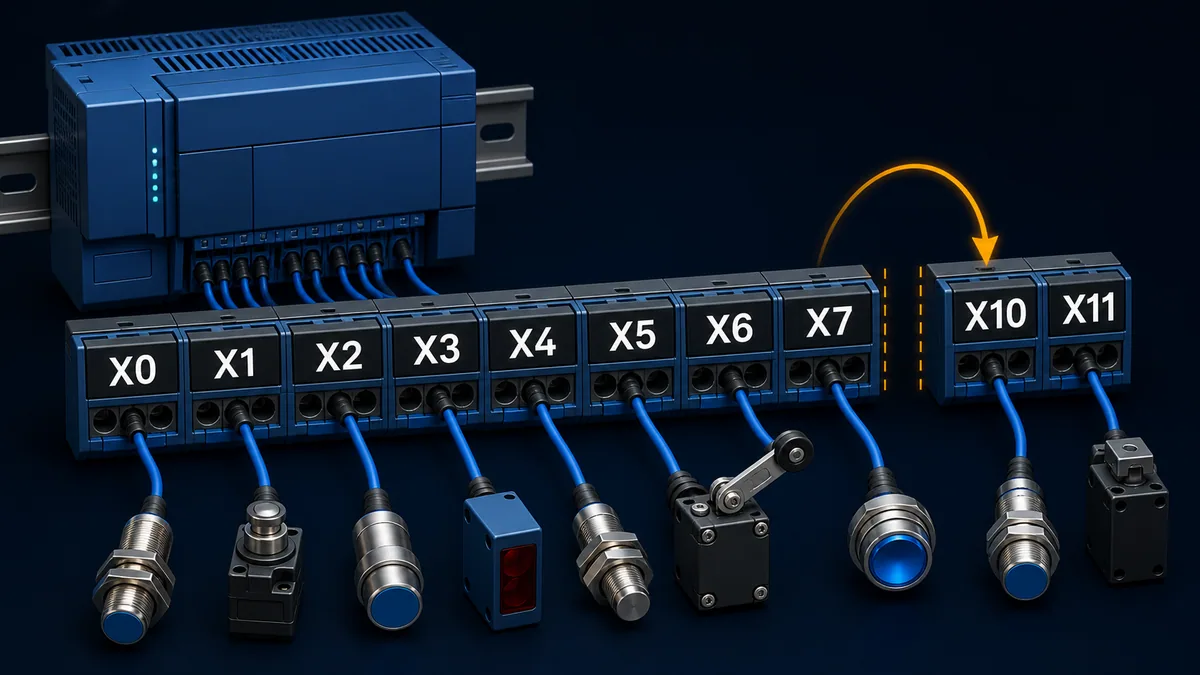
Handle octal X and Y addresses correctly
Convert the PLC label to a point index before adding the base
DVP X and Y device labels use octal digits. The sequence is 0, 1, 2, 3, 4, 5, 6, 7, 10, 11...; labels containing 8 or 9 are invalid in that octal sequence. To translate X10, interpret 10 as octal eight, then add eight to the X base 0x0400, producing PDU offset 0x0408. Do not add decimal ten and produce 0x040A.
For X17, octal 17 equals decimal 15, so the offset is 0x040F. For Y20, octal 20 equals decimal 16, so the offset is 0x0510. A tool with a Delta-native driver may accept X10 directly and perform the mapping. A raw Modbus client needs the correct object and offset.
| PLC label | Octal suffix as decimal point index | Base | PDU hex | PDU decimal | Delta display style |
|---|---|---|---|---|---|
X0 |
0 | 0x0400 |
0x0400 |
1024 | 101025 |
X7 |
7 | 0x0400 |
0x0407 |
1031 | 101032 |
X10 |
8 | 0x0400 |
0x0408 |
1032 | 101033 |
X17 |
15 | 0x0400 |
0x040F |
1039 | 101040 |
Y0 |
0 | 0x0500 |
0x0500 |
1280 | 001281 |
Y7 |
7 | 0x0500 |
0x0507 |
1287 | 001288 |
Y10 |
8 | 0x0500 |
0x0508 |
1288 | 001289 |
Y20 |
16 | 0x0500 |
0x0510 |
1296 | 001297 |
Prove I/O meaning beyond the response bit
For an input, compare the raw Modbus bit with the PLC device monitor and a safely stimulated, independently observed field condition. For an output, separate requested command, logic/permissives, PLC output image, physical module indication, terminal voltage/current and process response. Never force or write an output merely to discover its address on operating equipment.
Use read-only test points first. If a controlled output proof is required, follow the machine/process test plan, establish energy/process boundaries, verify interlocks and safe state, use qualified personnel and record rollback. Modbus success is only one layer of the proof.
Build and verify a D0 FC03 request
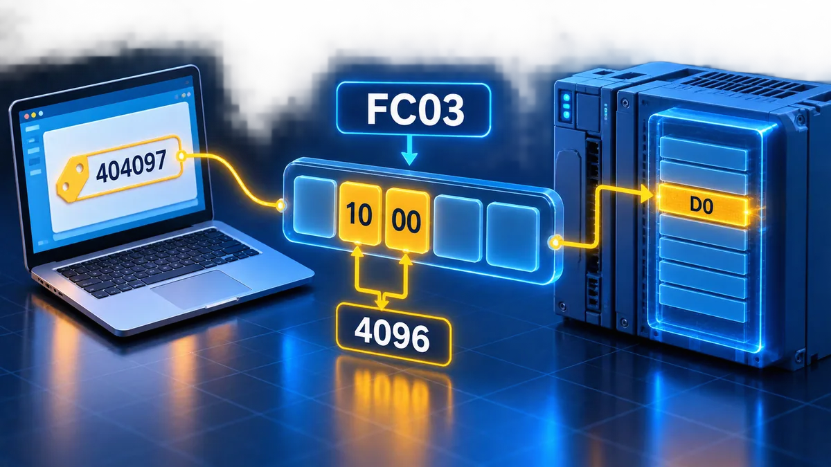
Convert D0 into the actual request bytes
For a DVP server at station/Unit ID 1, an FC03 request for one word at D0 uses start address 0x1000 and quantity 0x0001. The RTU application data before CRC is 01 03 10 00 00 01. Modbus RTU CRC is transmitted low byte first; the CRC for those six bytes is 80 CA, making the complete request 01 03 10 00 00 01 80 CA.
If D0 contains decimal 1234 (0x04D2), a representative RTU response is 01 03 02 04 D2 3A D9: station 1, FC03, two data bytes, big-endian register value, then CRC low/high. This example assumes the request is supported and the value remains stable. TCP carries the same function/start/quantity inside a Modbus TCP application data unit with an MBAP header and no RTU CRC.
| RTU request field | Bytes | Interpretation | Evidence check |
|---|---|---|---|
| Server address | 01 |
DVP station 1 | Match PLC port configuration and approved node plan |
| Function | 03 |
Read holding registers | Match D-word object and server support |
| Start address | 10 00 |
0x1000 = D0 in cited DVP table |
Do not send displayed 404097 as bytes |
| Quantity | 00 01 |
Read one 16-bit register | Stay within documented range/quantity |
| CRC low/high | 80 CA |
CRC-16 over preceding RTU bytes | Analyzer/client should calculate it |
| Expected response prefix | 01 03 02 |
Same station/function, two data bytes | Exception has function high bit set instead |
| Example data | 04 D2 |
One register equals decimal 1234 | Confirm signed/type/scale separately |
| Response CRC low/high | 3A D9 |
CRC for the example response | A different value produces a different CRC |
Use controlled values to expose off-by-one errors
Load or observe three distinct read-only test words, for example D0=111, D1=222 and D2=333, under a bench program approved for the exact CPU. Read one register using the client setting believed to target D0. If the result is 222, the client may be applying a one-based/zero-based translation differently. Capture the PDU start bytes; the capture resolves whether the request actually used 0x1000 or 0x1001.
Do not “fix” the project by subtracting one until the driver convention is documented. Record the selected object type, entered value, base setting and captured offset. Otherwise the same hidden adjustment will recur when tags are migrated to another driver.
Configure a safe RTU or TCP validation bench
Prove serial settings before interpreting registers
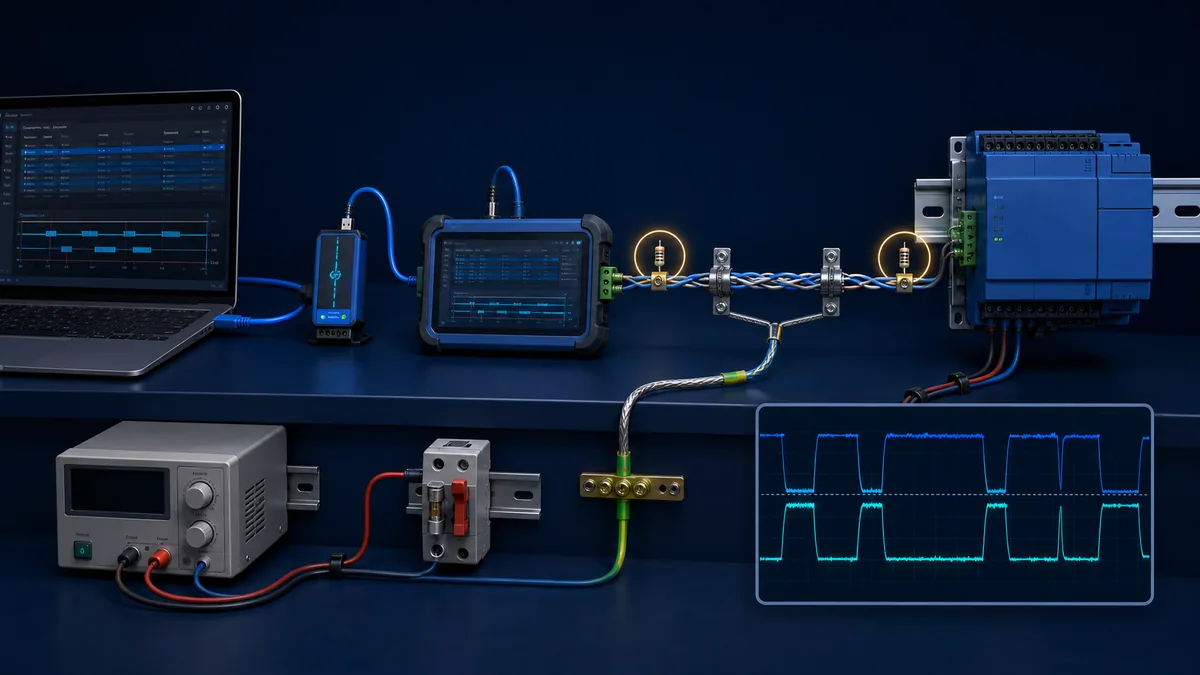
For Modbus RTU or ASCII, the client and DVP port must agree on mode, baud, data bits, parity, stop bits and station address. Confirm which built-in port or module supports the required role on the exact CPU. RS-485 also needs the approved cable/topology, polarity convention, reference/common-mode strategy, shield/bonding method, biasing where specified and termination only at physical ends according to the current device and Modbus serial guidance.
An address error normally produces a valid exception or valid data from the wrong location after a valid exchange. Silence can instead mean wrong station, serial format, wiring/polarity, port mode, interface, power or timing. CRC errors point toward frame corruption, serial mismatch or physical quality—not toward D0 versus D1 by themselves.
Keep Modbus TCP inside an approved OT test zone
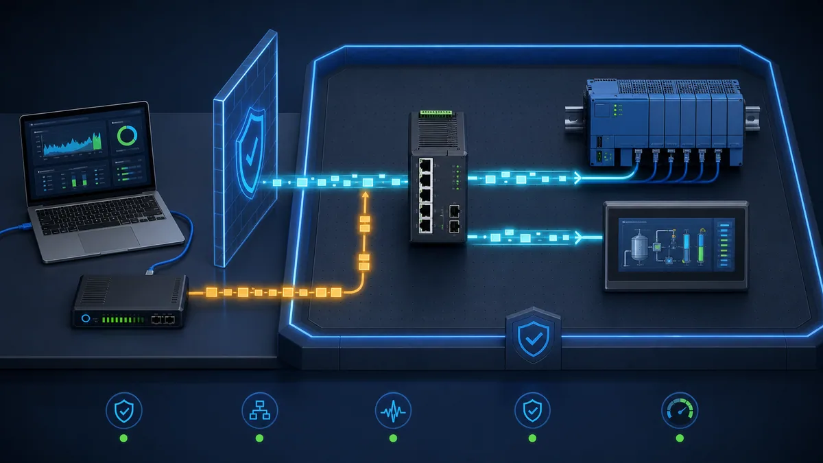
For Modbus TCP, verify the exact interface's server/client capability, IP/subnet/gateway settings, listening service/port, Unit ID handling, connection limits and timeout behavior. A successful ping proves IP reachability, not that the Modbus service, unit, function, address or application data is correct. Capture the MBAP Transaction ID, Protocol ID, length, Unit Identifier and PDU.
Do not expose a PLC's ordinary Modbus TCP service directly to the internet or assume the protocol provides authorization for writes. Place engineering/test access within the approved OT architecture, restrict flows and accounts where the surrounding products support them, preserve configuration backups and monitor Delta's product cybersecurity advisories for the exact product/firmware.
| Validation layer | RTU evidence | TCP evidence | Pass criterion |
|---|---|---|---|
| Physical/link | Port state, polarity/topology, termination, waveform if qualified | Link state, VLAN/switch port and errors | Stable path under defined load/environment |
| Transport framing | Mode, serial format, inter-frame timing, CRC | MBAP header, TCP connection/retransmission | Requests and responses frame correctly |
| Identity | Station address | IP plus Unit Identifier behavior | Exact intended endpoint responds |
| Function/object | Function byte | PDU function byte | Matches X/Y/M/T/C/D object and permission |
| Address | Captured start bytes | Captured PDU start bytes | Equals vendor-table zero-based offset |
| Quantity | Captured quantity | Captured PDU quantity | Within one valid mapped block and product limit |
| Data | Raw response bytes | Raw response bytes | Known test values match before type/scale |
| Application | Tag value, quality and age | Tag value, quality and age | Correct meaning, freshness and failure behavior |
Interpret words, double words and application data explicitly
A successful D-register read returns only 16 raw bits
D devices are 16-bit words in the DVP programming model, but an application may interpret one word as unsigned, signed two's-complement, flags, BCD or a scaled engineering value. Two or more D words may form 32-bit integers, floating-point values, counters, timestamps or strings. Modbus defines the byte order inside each 16-bit register; multi-register word order remains an application/vendor contract.
For a 32-bit test, choose a pattern whose bytes are all different, such as 0x11223344, and document the PLC memory arrangement plus expected client value. Test all four common byte/word interpretations only in a controlled environment, select the one proven by the exact producer contract and record it. Do not keep a “swap” option merely because one live value looks plausible.
| Contract field | Required record | Example failure |
|---|---|---|
| PLC devices | D100:D101 |
Client reads only one word |
| Width/type | Signed 32-bit integer | Negative value appears as a large positive number |
| Register order | First word high or low | Value bytes are swapped by 16-bit words |
| Byte order | High byte first in each Modbus register | Driver applies an extra byte swap |
| Scale/units | Raw count × 0.1 °C | Display is ten times too high |
| Valid range | Engineering and raw bounds | Corrupt/stale value passes as believable |
| Quality/age | Valid flag and last-update timestamp | Last good value remains green after communication loss |
| Write owner | PLC, HMI or recipe service | Two writers overwrite each other |
Design a stable interface area instead of exposing arbitrary memory
For a production SCADA/HMI interface, reserve a documented D/M block owned by the interface rather than exposing unrelated program internals. Include an interface version, heartbeat/counter, data-valid state, command/acknowledgement handshake, sequence number where needed, units/scales, bounds and write ownership. Keep safety functions and direct hazardous outputs outside a casual external write surface.
The map should survive program refactoring. If D500 is published as a pressure tag, its application meaning should not silently change because an engineer reused it for a recipe. Version the contract, test backward compatibility and coordinate client changes. Address translation is necessary but not sufficient interface design.
Troubleshoot by the first failed evidence boundary
Classify timeout, exception, wrong point and wrong value separately
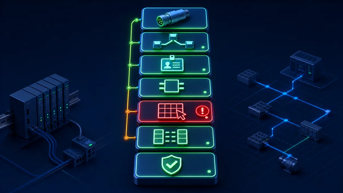
A timeout means no acceptable response arrived within the client's rules. It does not prove a bad register address. A Modbus exception is a valid response and can narrow the issue: illegal function, illegal data address or illegal data value point toward different request boundaries. A valid but wrong point often indicates base or octal conversion. A correct raw word with a wrong engineering value indicates type, word order, scale or application ownership.
Capture before changing several settings. Record request/response bytes, timestamp, client configuration, CPU/firmware, port parameters, project checksum, tested device, known PLC value and process state. Change one hypothesis at a time and retain the before/after evidence.
| Symptom | Most useful next evidence | Likely boundaries | Avoid |
|---|---|---|---|
| No response at all | Traffic capture at both ends, port/Unit/config state | Power, path, role, serial format, IP/service, identity | Changing register base first |
| CRC/framing errors | Serial settings, topology, waveform and error counters | Baud/parity/stop, interference, wiring/termination | Blaming D0 versus D1 |
| Exception 01 | Function code and exact server support | Unsupported/disabled function | Repeating faster |
| Exception 02 | Captured function/start/quantity versus exact CPU table | Wrong object, gap, range or quantity | Adding one blindly |
| Reads D1 when D0 expected | Captured PDU start and client base setting | Zero/one-based client translation | Editing PLC memory to compensate |
| X point shifted after X7 | PLC suffix interpreted as decimal | Octal conversion | Creating invalid X8/X9 labels |
| Low M works, high M fails | Compare M1535/M1536 block mapping | Documented discontinuity or CPU range | Extending 0x0800+n across gap |
| D4095 works, D4096 fails | Compare 0x1FFF to documented 0x9000 |
Documented D-block discontinuity | Requesting 0x2000 |
| Raw word correct, value nonsense | Byte/word pattern, type, scale and units | Application interpretation | Rewiring the network |
| Data freezes after loss | Tag quality/age and PLC/client failure logic | Application stale-data handling | Treating last value as healthy |
Use negative tests to prove the checker and recovery path
On an isolated bench, deliberately request one known unsupported function or out-of-range address and verify that the client records the exception without substituting a valid value. Disconnect the approved test path and prove quality becomes bad/stale within the specified time. Restore it and verify controlled recovery, sequence/handshake behavior and event logging.
Negative tests must not write or energize unintended points. Prefer read-only faults, simulator cases and a spare/test CPU. For production testing, use the approved change, isolation and process-risk procedure. Restore exact configuration and compare checksums afterward.
Commission the mapping as a controlled interface
Use a staged acceptance sequence
Begin offline with the exact manuals, address worksheet and client convention. Then validate one read-only bit, one read-only word, one block boundary, one octal transition and one multiword pattern on a bench. Only after those pass should the project test normal production read volume, authorized writes, timeout/retry behavior, stale data, restart and rollback.
| Stage | Test | Pass evidence | Stop condition |
|---|---|---|---|
| 1. Identity | CPU/firmware/port/driver match approved record | Archived screenshots/exports/manual revisions | Any unknown product or role |
| 2. Static map | Device → hex → PDU → client worksheet | Independent review and formula boundary checks | Formula crosses undocumented gap |
| 3. One bit | Known read-only X or M point | PLC monitor, capture and client agree | Function/object mismatch |
| 4. One word | Known D value at D0 | 0x1000 capture and exact raw value |
Base mismatch or exception |
| 5. Boundaries | X7/X10, M1535/M1536, D4095/D4096 as implemented | Each request uses documented offset | CPU does not implement test range |
| 6. Data model | Signed, scale and 32-bit pattern | Raw and engineering values agree | Ambiguous word/byte order |
| 7. Degraded cases | Timeout, exception, stale and reconnect | Quality/age/alarm/recovery meet design | Silent last-value acceptance |
| 8. Load | Intended poll groups, rates and clients | Stable response/PLC/network performance | Rising errors or deadline failure |
| 9. Authorized writes | Handshake/bounds/interlocks in safe state | Command, acknowledgement and process proof | Uncontrolled direct write |
| 10. Release | Backup, checksum, rollback, ownership and monitoring | Witnessed acceptance record | Missing rollback or owner |
Preserve an address worksheet that another engineer can reproduce
For every tag, retain PLC symbol, description, CPU family/manual revision, access, Modbus object/function, Delta communication hex, PDU decimal, client-entered value, base setting, width/type, word order, scale/units, valid range, quality/age, owner, poll group and test evidence. Include the captured request and response for representative points and every discontinuity.
A screenshot of a green tag is not sufficient. The next engineer needs to know why the address is correct, how it appears on the wire and what failure looks like. Revalidate after CPU/firmware, project, port/module, driver, network path, client version, scan group or data-contract changes.
Handle safety, security and lifecycle boundaries
Do not use address discovery as an output test on live machinery
Writing Y, M or D can change machine commands, setpoints or hidden state. A successful FC05/FC06/FC15/FC16 transaction does not bypass the requirement for authorized design, interlocks, risk controls and safe commissioning. Follow applicable site energy-control, electrical and process procedures. US readers should place OSHA 1910.147 and 1910.333 within their applicable scope; local law and site rules may be stricter or different.
For remote commands, use a defined command/acknowledgement interface with permissives, bounds, source ownership, sequence or anti-repeat logic as required, timeout and operator indication. Safety functions require their own validated safety architecture; an ordinary Modbus write is not a safety command channel merely because the PLC program uses it.
Restrict and monitor the surrounding OT access path
Classic Modbus lacks the authorization semantics many modern applications expect. NIST SP 800-82 Rev. 3 calls for OT controls that respect safety, reliability and performance. Segment systems, allow only required client-to-server flows, restrict engineering access, protect project/client backups and credentials, log changes, monitor abnormal requests and test recovery. Check Delta's current advisory page for the exact product and firmware.
Do not solve a conversion problem by opening broad network access or enabling every write function. Connectivity, protocol capability and business/process authorization are separate controls.
Diagnostic answer map for Delta PLC Modbus address questions
If someone asks for the Delta PLC Modbus address of D0
For the cited DVP map, D0 is Delta communication address H1000, PDU offset 4096 and Delta displayed holding-register reference 404097. Use FC03 to read it; enter 4096 in a zero-based holding-register client, 404097 in a compatible extended-reference client, or D0 in a verified Delta-native driver. Confirm the exact CPU/manual and capture bytes 10 00.
If someone asks why D0 is 404097 instead of 40001
40001 denotes the first holding-register reference at PDU offset zero in common notation. Delta maps DVP D0 to PDU offset 0x1000 (4096), so its one-based extended reference is 400001 + 4096 = 404097. The PDU still carries only 0x1000, not the human label.
If someone asks for the Delta PLC Modbus address of X10
For the cited DVP map, interpret 10 as octal eight. Add point index eight to X base 0x0400, giving PDU offset 0x0408 (1032) under FC02/discrete inputs and Delta display 101033. Confirm the point exists on the exact CPU/I/O configuration.
If someone asks why a high D or M address fails
Check documented block discontinuities and the CPU's effective range. D4096 begins at 0x9000, not 0x2000; M1536 begins at 0xB000, not 0x0E00. Split requests at map boundaries and do not extend a low-block formula into a high block.
If someone asks whether the same table works for AS or AH PLCs
No universal claim is safe. Delta lists distinct DVP, AS, AH and AX families. Select the exact CPU and current manual/driver table. Use this page's numeric examples only for the cited DVP communication map.
If someone asks how to test the address without real hardware
Use the Modbus simulator lab to practise function codes, zero-based offsets, request frames, exceptions and stale-data diagnosis. A browser lab does not emulate a specific Delta CPU's firmware, port, special devices, discontinuous map or electrical layer; verify those on an approved test setup.
Frequently asked questions
What is the Modbus address of D0 in a Delta DVP PLC?
The cited Delta DVP application manual maps D0 to hexadecimal communication/PDU address 0x1000, decimal offset 4096 and displayed Modbus holding-register reference 404097. In a zero-based client select holding registers/FC03 and enter 4096. Confirm the exact CPU implements the range and the driver does not subtract or add one automatically.
Is 404097 sent in the Modbus request?
No. The request uses FC03 plus start-address bytes 10 00. The leading 4/object notation and one-based presentation belong to the human/client representation. A captured PDU is the most reliable way to see what the client actually sent.
Why does my Modbus client require 4096 instead of 404097?
It likely separates the object type from the zero-based offset. Choose holding registers and enter 4096. Another client may accept extended 4xxxxx references or a Delta-native D0 symbol. Record the driver/base convention; do not assume all clients use the same input format.
What is the Delta DVP Modbus address of M0?
The cited DVP table maps M0 to PDU address 0x0800 (2048) and displayed coil reference 002049. Read with FC01. Writes require exact CPU support and an authorized application design; never toggle an unknown M bit in a running machine.
What is the Delta DVP Modbus address of X0 and Y0?
X0 maps to 0x0400 (1024), displayed as discrete input 101025 and read with FC02. Y0 maps to 0x0500 (1280), displayed as coil 001281 and read with FC01. The exact physical points and safe use depend on CPU/module configuration and wiring.
Why does X10 come after X7 in a Delta PLC?
DVP physical X/Y suffixes use octal numbering. Octal 10 equals decimal point index eight, so X10 follows X7. For the DVP map, X10 becomes base 0x0400 + 8 = 0x0408, not 0x040A.
Can I calculate every Delta D address as 4096 plus the device number?
Only inside the documented contiguous D0:D4095 block. D4096 jumps to 0x9000. Higher implemented ranges must be taken from the exact DVP table/CPU manual. Never span a discontinuity with one Modbus block request.
Are Delta PLC Modbus RTU and Modbus TCP register addresses the same?
The application PDU function/start-address concept can be the same when an exact product exposes the same server map, but transport framing, endpoint identity, configuration, limits and Unit ID behavior differ. RTU uses station/framing/CRC; TCP uses IP/TCP and an MBAP header. Verify the exact interface manual.
Does a valid Modbus response prove the field device is working?
No. It proves that a server returned data for a request. You still need to prove correct point identity, type/scale, data age/quality, PLC logic, I/O electrical state and process response. A readback of Y0 is not independent proof that the actuator moved.
How should I troubleshoot Modbus exception 02 on a Delta DVP PLC?
Capture the function, start offset and quantity, then compare them with the exact CPU's implemented DVP block. Check object type, zero/one-based conversion, octal X/Y suffixes, D/M discontinuities and whether the request crosses a map boundary. Exception 02 is useful valid evidence; do not change wiring first.
Sources, review scope, and limitations
Primary sources used for this guide
- Delta current PLC family page: current DVP, AS, AH and AX family/software scope used to prevent a universal-map claim.
- Delta DVP-PLC Application Manual: official DVP device functions, communication-address blocks, ranges and communication programming context.
- Delta DVP starter-kit manual: official effective-range and DVP mapping examples for named starter CPUs.
- Delta Kepware integration application note: official D0/
404097third-party client example and tested integration context. - Delta InTouch integration application note: official DVP device/address table and SCADA configuration context.
- Delta DIAView SCADA user manual: official evidence that Delta DVP, AS and AH device/address handling is differentiated in Delta software.
- Modbus Organization specifications page: current official index and scope for application, serial-line, TCP and security documents.
- Modbus Application Protocol Specification V1.1b3: official data model, addressing, encoding, function and exception definitions.
- Modbus Serial Line Protocol and Implementation Guide V1.02: official RTU/ASCII framing, timing, physical-layer and implementation guidance.
- Delta Product Cybersecurity Advisory page: current vendor advisories and mitigation notices for exact affected products.
- NIST SP 800-82 Rev. 3: current final US OT-security guidance for safety, reliability, performance and cybersecurity controls.
- OSHA 1910.147 hazardous-energy control and OSHA 1910.333 electrical work practices: US isolation and electrical work-practice boundaries in their applicable scope.
Review and safety limitations
This guide is an educational DVP address-translation and validation framework. It is not a replacement for the current exact-CPU/application/module manual, Delta support decision, approved PLC/SCADA interface specification, Modbus conformance test, RS-485/Ethernet design, cybersecurity architecture, machine/process risk assessment, safety validation or energized-work procedure. DVP mappings are included only where grounded in the cited official table; an address row does not prove that every DVP CPU implements the full range or accepts every function/write.
The D500, boundary, octal and FC03 examples are calculated test cases. The response value 1234, multiword pattern and acceptance values are educational, not production setpoints or universal test limits. Client notation differs: verify the exact driver manual and capture the PDU. AS, AH, AX, motion CPUs, special modules, gateways and third-party devices require their own current maps.
The eight original generated visuals are explanatory abstractions. The unbranded PLCs, modules, terminals, waveforms, network/security boundaries, byte cards and application displays do not represent an exact Delta product, certified wiring, real packet capture or approved safety/cybersecurity design. Decorative bytes in the translation-chain visual are not commands; only the explicitly captioned D0 worked illustration carries the reviewed conversion.
Use current documentation and firmware for the exact CPU/interface/module and client; approved project, tag and network records; a spare/test system where practical; suitable isolated interfaces and qualified instruments; qualified automation/network/electrical/process/safety personnel; and site change, isolation, hazardous-area and cybersecurity procedures. Revalidate after any CPU/firmware, project/device-range, port/module, station/Unit, serial/IP, driver/base, function/quantity, tag/type/scale, client poll/load, wiring/topology, security-path or process-permission change. Review this page when cited Delta or Modbus documentation changes.
Now run it · free to start
Learn Modbus, then the networks around it
Modbus first because it is simple and everywhere, then the Ethernet-based protocols and the SCADA layer above them. Free to start.
Ownership disclosure: PLC Programming IO and PLC Simulation Software are operated by the same publisher.
PLC Programming IO Editorial Team
Industrial automation education, references, and software testing
The PLC Programming IO Editorial Team publishes sourced industrial-automation education and documents how material is reviewed, tested, and corrected. A team byline means the publisher is responsible for the page; it does not represent a fictional person or imply an engineering licence.
Coverage:
- • PLC programming concepts and examples
- • Vendor software tutorials and comparisons
- • SCADA, HMI, protocols, and instrumentation
- • Training, careers, and reference material
Review standard:
- • Prefer primary and official sources
- • Record software versions when material
- • Separate tested facts from estimates
- • Publish material corrections
Important scope note
This site provides education, not project-specific engineering approval. Safety, code, and compliance decisions require a qualified person with access to the actual machine and jurisdiction.