PLC Programming: Languages, Workflow and Real-World Examples
PLC programming turns an industrial control requirement into scheduled controller logic, verified I/O behavior, diagnostics and release evidence. Learn the complete workflow with a two-pump example.
PLC programming in one precise answer
PLC programming is the engineering process that converts a machine or process requirement into scheduled controller software, typed data, commands, diagnostics and test evidence. A usable PLC program reads configured inputs, evaluates logic in a declared execution context, writes authorized output commands, checks feedback and exposes enough state for operators and technicians to understand what happened. The code is only one deliverable; the I/O contract, task timing, fault behavior, restart rules, approved project and acceptance record are part of the program too.
The current IEC 61131-3:2025 Edition 4 specifies one textual language—Structured Text (ST)—and two graphical languages—Ladder Diagram (LD) and Function Block Diagram (FBD). Sequential Function Chart (SFC) supplies graphical and equivalent textual elements for organizing programs and function blocks. A vendor may implement a conforming subset plus product-specific instructions and project structures. IEC vocabulary therefore improves transfer of knowledge, but it does not make native project files, data layouts, timer details, online changes or hardware behavior interchangeable.
Practical rule: begin with observable behavior and evidence, not with a favorite language. Define what the equipment must do, what can prevent it, how success is proved, what happens on loss of power or communication, and which tests will demonstrate the result. Then allocate each part to LD, ST, FBD or SFC where that representation is clearest on the chosen platform.
What this guide owns—and what its specialist guides retain
This is the broad requirements-to-deployment owner. It explains how the pieces fit together and follows one two-pump example through contracts, code, traces, tests and controlled change. It does not replace the deeper pages below.
| If your next question is… | Use this specialist owner | Why it stays separate |
|---|---|---|
| How do I build a complete ladder program? | PLC ladder logic program | Full rungs, scan traces, state ownership and ladder acceptance tests |
| What does each ladder symbol mean? | Ladder logic symbols and instructions | Lookup-oriented instruction and symbol reference |
| How do I write IEC Structured Text? | Structured Text programming guide | Syntax, types, functions, function blocks and executable examples |
| How do I choose among PLC languages? | PLC programming languages | Language-by-language comparison and learning path |
| Which software should I install? | PLC programming software | Platform, licensing, operating-system and compatibility selection |
| How should a beginner learn? | PLC programming beginner roadmap | Sequenced training path, exercises and milestones |
| How do I diagnose a stopped machine? | PLC troubleshooting method | Field-first fault isolation across power, I/O, network, logic and load |
| How do I implement a specific vendor? | Allen-Bradley programming guide, Siemens programming guide, CODESYS and Beckhoff guide | Exact project, task, data, download and online workflows |
What a PLC program actually contains
A PLC application is not merely a list of Boolean equations. It is a set of related contracts executed by a controller and connected to a physical process. Mature projects make those contracts visible.
| Term | Precise working meaning | Evidence an engineer should retain |
|---|---|---|
| requirement | Testable statement of required behavior and constraints | approved user/control requirement with identifier |
| control narrative | Ordered explanation of modes, sequences, interlocks and abnormal behavior | reviewed narrative linked to tests |
| I/O contract | Meaning, type, electrical source, range, quality and ownership of every boundary signal | I/O list, drawings, channel configuration and loop-check record |
| tag or variable | Named, typed software value; it may represent field data, state, command, feedback or evidence | declaration, scope, unit and source/consumer map |
| task | Scheduling context that determines when a program is called | period/event, priority, watchdog and measured execution time |
| program organization unit | IEC term covering programs, functions and function blocks | interface, instances, call hierarchy and version |
| routine or method | Vendor/project subdivision containing executable logic | confirmed call path and language |
| request | Desired action from an operator, sequence or supervisory system | requesting owner, validation and expiry/cancel behavior |
| command | PLC decision sent toward an output or device | single writer, permissives and force/override state |
| feedback | Independent observation that the requested physical response occurred | input source, expected transition and timeout |
| state | Memory that carries behavior across scans | writer, reset/restart rule and diagnostic exposure |
| fault | Latched or current abnormal condition with defined response | first-out cause, timestamp/context, reset criteria and test |
| build or compile | Toolchain transformation and validation of a specific project for a target | tool version, project hash/export, warnings and result |
| FAT/SAT | Factory/site acceptance testing against approved criteria | test version, result, evidence, exception and sign-off |
The distinction between request, command and feedback is especially important. AutoRequest can be true while a permissive blocks Pump1Command. Pump1Command can be true while a contactor, drive, wiring path or motor fails to produce Pump1Running. If all three are collapsed into one bit, the HMI may say “running” when the PLC has only asked for motion.
The end-to-end PLC programming workflow
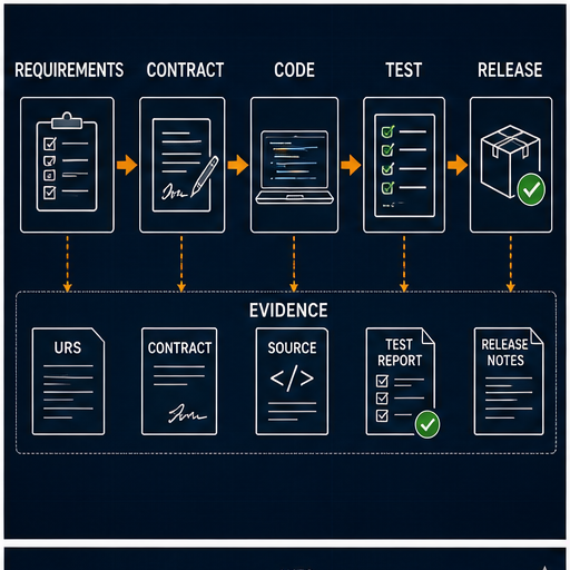
The workflow below is deliberately independent of brand. Tool names change; the engineering gates do not.
| Gate | Main question | Minimum output | Failure prevented |
|---|---|---|---|
| 1. scope and hazards | What is controlled, and what is outside standard control logic? | system boundary, risk references and responsible parties | unsafe assumptions and hidden scope |
| 2. requirements | What observable behavior must occur in every mode and failure? | numbered, testable requirements | coding an ambiguous narrative |
| 3. I/O and data | Which signal proves each condition, with what type, unit and quality? | I/O/tag contract | logic built on the wrong channel or meaning |
| 4. architecture | Which tasks, programs, modules and state owners execute the behavior? | call tree, periods, priorities and interfaces | unreachable logic and timing surprises |
| 5. implementation | Which language expresses each responsibility clearly? | reviewed source and generated/reference data | monolithic or opaque code |
| 6. offline verification | Does behavior match the contract at normal and boundary cases? | static checks, simulation traces and reviewed exceptions | discovering logic defects at the machine |
| 7. target verification | Does the exact compiler/controller/configuration behave as required? | successful build, identity manifest and target tests | confusing a generic model with the real runtime |
| 8. FAT and SAT | Do integrated panels, devices and the installed process meet criteria? | signed results, defects and retests | accepting software-only evidence as machine proof |
| 9. release and recovery | Can the approved state be restored and changes attributed? | backups, hashes/versions, access and rollback plan | uncontrolled online edits and unrecoverable downtime |
1. Turn prose into observable requirements
“Control two pumps automatically” is not yet programmable. It omits thresholds, hysteresis, availability, proof, duty selection, failure response, manual behavior and restart. A useful requirement has an identifier and a result that a witness can observe.
For the worked wet-well example in this guide, assume these training requirements:
| ID | Requirement | Observable acceptance criterion |
|---|---|---|
| R-01 | automatic cycle enable | with AutoEnable, healthy level quality and at least one available pump, the state leaves IDLE when level reaches 70% |
| R-02 | lead demand | the selected lead pump is commanded at or above 70%, subject to permissives |
| R-03 | lag demand | the other available pump is commanded at or above 85% while demand persists |
| R-04 | stop hysteresis | both automatic commands turn off only when level falls to or below 35% |
| R-05 | response proof | a commanded pump must return running feedback within 3.0 s or latch a start-fail fault |
| R-06 | failover | if the selected lead becomes unavailable or fails to prove, the other healthy pump is requested when automatic demand remains |
| R-07 | alternation | after a completed automatic cycle, the next healthy lead changes from P1 to P2 or P2 to P1 |
| R-08 | bad input quality | invalid level quality removes automatic commands and exposes a distinct diagnostic |
| R-09 | restart | after controller restart, automatic outputs remain off until valid inputs and the restart policy have been evaluated |
| R-10 | safety boundary | emergency-stop, guarding and electrical protection are provided and validated by their engineered systems; standard example logic consumes status only |
These thresholds and delays are teaching assumptions, not pump-station design recommendations. A real design derives setpoints, capacity, minimum run/rest time, starts per hour, overflow risk and failure actions from the process, equipment data, risk assessment and applicable requirements.
2. Freeze the I/O and data contract before writing rungs
An address such as %IX0.3 or Local:2:I.Data.3 is not a requirement. Give the signal an engineering name, retain the physical mapping separately and declare the semantics that code may rely on.
| Tag | Type/unit | Source or writer | True/value meaning | Quality/restart rule |
|---|---|---|---|---|
LevelPct |
REAL, % | scaled analog-input service | validated wet-well level, 0–100% engineering range | consumers require LevelQualityGood; initialize invalid |
LevelQualityGood |
BOOL | input/diagnostic service | channel, range and update-age checks are acceptable | false on startup until proven |
AutoEnable |
BOOL | validated mode service | automatic control is permitted by the selected operating mode | state derived from physical/HMI ownership policy |
P1Available |
BOOL | equipment module | P1 is selected, healthy and permitted for automatic request | fail false on stale essential status |
P2Available |
BOOL | equipment module | P2 is selected, healthy and permitted for automatic request | fail false on stale essential status |
P1Running |
BOOL | independent field feedback | P1 run feedback is present | not inferred from command |
P2Running |
BOOL | independent field feedback | P2 run feedback is present | not inferred from command |
P1AutoRequest |
BOOL | sequence | automatic process requests P1 | cleared every scan before state logic writes it |
P2AutoRequest |
BOOL | sequence | automatic process requests P2 | cleared every scan before state logic writes it |
P1Command |
BOOL | P1 equipment module only | authorized standard command toward the output/device | false until mode, interlocks and module policy evaluate |
P2Command |
BOOL | P2 equipment module only | authorized standard command toward the output/device | same boundary as P1 |
P1StartFail |
BOOL | P1 diagnostic module | command did not receive feedback within configured proof time | latched until safe, authorized reset criteria pass |
P2StartFail |
BOOL | P2 diagnostic module | equivalent P2 start failure | same rule as P1 |
CycleState |
enumerated | sequence only | IDLE, LEAD, LAG, STOPPING or FAULTED |
explicit startup state and transition policy |
LeadPump |
enumerated | alternation manager only | selected first pump for the next/current cycle | restore only if validated; otherwise deterministic default |
This contract makes ownership testable: the sequence owns requests, each equipment module owns its command and fault, and the input service owns quality. Avoid multiple coils, assignments or HMI writes to the same command. A single-writer rule lets reviewers find the controlling expression and lets diagnostics explain why it is false.
3. Design execution before detailed logic
PLC code is evaluated in an execution model, not in an abstract vacuum. Inputs may be refreshed independently of a program task; periodic tasks can pre-empt lower-priority work; communication data can arrive asynchronously; conditional calls can freeze function-block state; and a watchdog can fault when execution exceeds its budget. Exact behavior is product- and configuration-specific.
Rockwell’s current tasks, programs and routines documentation describes tasks as the scheduling mechanism, programs as related routines plus tags, and routines as executable blocks. CODESYS Task Configuration likewise defines tasks as the chronological flow units controlling program call chains. Those are useful architectural parallels, not proof that the runtimes are identical.
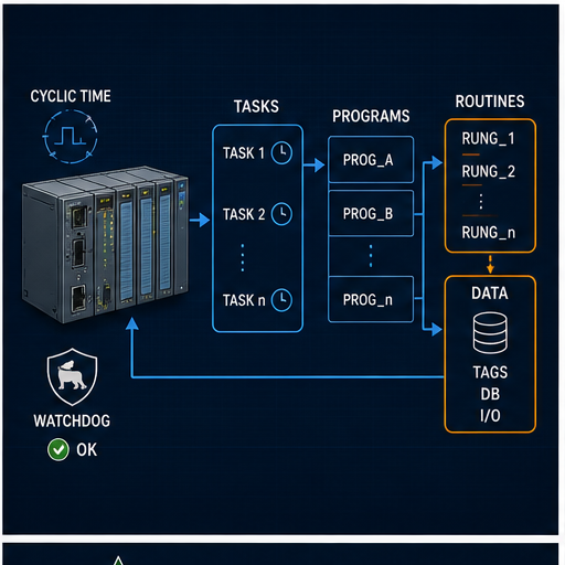
For a modest two-pump controller, a defensible starting architecture might be:
| Execution unit | Example period | Responsibility | Timing evidence |
|---|---|---|---|
| input/diagnostic task | 20 ms | acquire mapped inputs, validate range/quality/age and publish an input snapshot | configured period, maximum execution, stale-data test |
| application task | 50 ms | modes, pump equipment modules, alternation and sequence | configured period, priority, worst observed time, overlap/watchdog status |
| HMI/SCADA service | 250 ms | command validation, status publication, alarm-facing data | communication update/timeout and stale-data behavior |
| historian/reporting | 1,000 ms | non-control aggregation and counters | no control dependency on successful reporting |
The values are examples only. Verify the exact target’s I/O update model, task types, priority rules, timer basis, watchdog response and communication behavior. Measure execution with representative worst-case branches and data, not with an empty project.
Choose PLC languages by responsibility
“Which PLC language is best?” is incomplete. The better question is: which representation makes this responsibility easiest to verify, diagnose and maintain on the target platform? One application can use more than one IEC language without becoming inconsistent if interfaces and ownership stay clear.
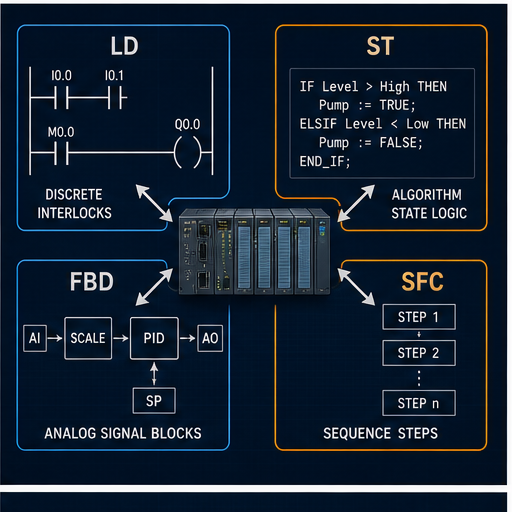
| Language | Strong fit | Weak-fit warning | Evidence reviewers need |
|---|---|---|---|
| Ladder Diagram (LD) | discrete permissives, interlocks, command authorization and technician-facing Boolean paths | dense mathematics, large array processing or hidden state spread across duplicate coils | rung order, state elements, call path, instruction behavior and scan trace |
| Structured Text (ST) | algorithms, bounded loops, data transformation, state machines and reusable typed logic | compressed expressions with implicit priorities or unbounded scan work | types, bounds, transition priority, overflow/error policy and tests |
| Function Block Diagram (FBD) | analog signal chains, control blocks and visually connected transformations | crossed-page wiring, ambiguous execution order or stateful blocks without instance discipline | signal units, block instances, execution order, modes, limits and quality path |
| Sequential Function Chart (SFC) | visible steps, transitions, parallel/alternative branches and procedural coordination | using steps as a substitute for equipment modules, or leaving abort/restart semantics implicit | active-step behavior, transition priority, action qualifiers, holds, aborts and restart tests |
Ladder Diagram for an authorization path
For one pump, the conceptual command rule is readable as a stop-dominant Boolean contract:
P1Command := P1AutoRequest
             AND AutoEnable
             AND P1Available
             AND LevelQualityGood
             AND NOT P1StartFail
             AND StandardControlPermissive;
In ladder this becomes series enabling contacts driving one command coil, often with branches for separately authorized manual and automatic requests. The final rung must not pretend that StandardControlPermissive implements a safety function. It is an ordinary status supplied across a designed boundary; safety-rated behavior requires the appropriate architecture, hardware, lifecycle and validation.
Structured Text for state and priority
ST makes mutually exclusive transitions and priority explicit when it is written as a state machine. Put abnormal or stop-dominant conditions before start/advance conditions, write each request from one place, and bound every loop. Avoid assuming that line order compensates for multiple writers elsewhere.
Function Block Diagram for a quality-aware analog path
An analog chain is more than raw → scale → PID → output. A useful FBD design carries channel quality, engineering unit, clamp status, mode, limits and output tracking. If the process value is invalid, define whether the controller freezes, substitutes, goes manual, commands a safe process value or transfers control. The answer is application-specific and may be safety-significant.
SFC for procedural coordination
SFC can show IDLE → FILL → MIX → DRAIN clearly, but every transition still requires precise Boolean meaning. Define what happens when two transitions become true together, when an action is held, when equipment fails, when the operator pauses, and after power restoration. PLCopen publishes dedicated SFC structuring guidance; verify action and online-edit behavior in the chosen vendor implementation.
Worked PLC programming example: two-pump wet well
This example is deliberately small enough to inspect but deep enough to expose real design issues. It is a behavioral training example, not a complete pump-station design. It excludes hydraulic sizing, motor protection, hazardous-area design, electrical drawings, functional safety, telemetry, local hand circuitry, environmental ratings and vendor-specific output interfaces.
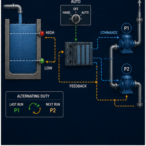
State model and transition priority
| State | Automatic requests | Normal transition | Higher-priority transition |
|---|---|---|---|
IDLE |
both false | level ≥ 70% and valid conditions → LEAD |
invalid quality/no available pump → remain off with diagnostic |
LEAD |
selected healthy lead true | level ≥ 85% and lag available → LAG; level ≤ 35% → STOPPING |
lead unavailable/start-fail → request healthy alternate or FAULTED |
LAG |
both available pumps true | level ≤ 35% → STOPPING |
any pump unavailable → remove only its request; neither available → FAULTED |
STOPPING |
both false | feedbacks off or stop timeout handled → alternate lead and return IDLE |
feedback stuck/other configured fault → FAULTED |
FAULTED |
both false in this teaching policy | authorized reset plus valid recovery criteria → IDLE |
invalid conditions keep state faulted |
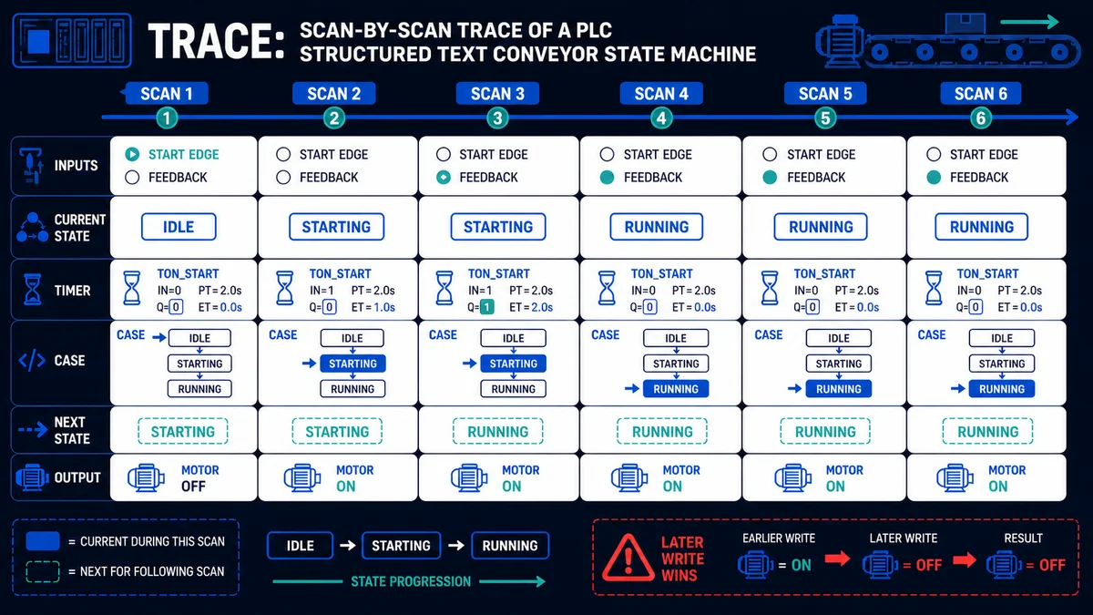
The sequence clears P1AutoRequest and P2AutoRequest at the start of every scan, then writes them according to exactly one state. The equipment modules execute after the sequence so commands reflect the current request in the same task invocation. If the chosen platform calls equipment first, commands will lag by one task period; that may be acceptable, but it must be declared and tested.
IEC-style Structured Text behavior oracle
The following excerpt expresses the sequence. Exact enumeration, timer and initialization syntax varies by tool. The downloadable oracle includes declarations, proof timers and an explicit restart input so it can be adapted as one file.
P1AutoRequest := FALSE;
P2AutoRequest := FALSE;

IF RestartHold OR NOT LevelQualityGood OR NOT AutoEnable THEN
    CycleState := IDLE;
ELSE
    CASE CycleState OF
        IDLE:
            IF LevelPct >= StartLeadPct THEN
                CycleState := LEAD;
            END_IF;

        LEAD:
            IF LeadPump = PUMP_1 THEN
                P1AutoRequest := P1Available AND NOT P1StartFail;
                IF (NOT P1Available OR P1StartFail) AND P2Available THEN
                    P2AutoRequest := TRUE;
                END_IF;
            ELSE
                P2AutoRequest := P2Available AND NOT P2StartFail;
                IF (NOT P2Available OR P2StartFail) AND P1Available THEN
                    P1AutoRequest := TRUE;
                END_IF;
            END_IF;

            IF LevelPct <= StopPct THEN
                CycleState := STOPPING;
            ELSIF LevelPct >= StartLagPct AND P1Available AND P2Available THEN
                CycleState := LAG;
            ELSIF NOT P1Available AND NOT P2Available THEN
                CycleState := FAULTED;
            END_IF;

        LAG:
            P1AutoRequest := P1Available AND NOT P1StartFail;
            P2AutoRequest := P2Available AND NOT P2StartFail;
            IF LevelPct <= StopPct THEN
                CycleState := STOPPING;
            ELSIF NOT P1Available AND NOT P2Available THEN
                CycleState := FAULTED;
            END_IF;

        STOPPING:
            IF NOT P1Running AND NOT P2Running THEN
                IF LeadPump = PUMP_1 THEN LeadPump := PUMP_2;
                ELSE LeadPump := PUMP_1;
                END_IF;
                CycleState := IDLE;
            END_IF;

        FAULTED:
            IF ResetAccepted AND LevelQualityGood THEN
                CycleState := IDLE;
            END_IF;
    END_CASE;
END_IF;
This sequence does not write physical outputs. Each pump module converts its request into a command only after validating mode, availability, interlocks and fault state. Its proof timer runs while command is true and feedback is false. A separate stop-response policy can detect feedback that remains true after the command is removed.
Scan-by-scan trace
Assume a 50 ms application task, P1 selected as lead, both pumps healthy, 3.0 s start-proof limit and valid level quality. Rows are selected observations, not every scan.
| Observation | Level | State at entry | P1 request / command / feedback | P2 request / command / feedback | Result and evidence |
|---|---|---|---|---|---|
| 1 | 60% | IDLE |
0 / 0 / 0 | 0 / 0 / 0 | below lead threshold; no demand |
| 2 | 70% | IDLE |
0 / 0 / 0 | 0 / 0 / 0 | transition selects LEAD; output depends on stated call/order policy |
| 3 | 70% | LEAD |
1 / 1 / 0 | 0 / 0 / 0 | P1 proof timer begins |
| 4 | 72% | LEAD |
1 / 1 / 1 | 0 / 0 / 0 | P1 feedback arrives before 3.0 s; no start fail |
| 5 | 85% | LEAD |
1 / 1 / 1 | 0 / 0 / 0 | transition selects LAG |
| 6 | 86% | LAG |
1 / 1 / 1 | 1 / 1 / 0 | P2 command begins and is awaiting proof |
| 7 | 84% | LAG |
1 / 1 / 1 | 1 / 1 / 1 | both responses proved; hysteresis prevents chatter |
| 8 | 35% | LAG |
1 / 1 / 1 | 1 / 1 / 1 | transition selects STOPPING |
| 9 | 34% | STOPPING |
0 / 0 / 1 | 0 / 0 / 1 | commands removed; feedback decay is observed separately |
| 10 | 34% | STOPPING |
0 / 0 / 0 | 0 / 0 / 0 | cycle completes; next lead becomes P2; returns IDLE |
Now replay with P1 feedback held false. When the proof timer reaches its configured limit, the P1 module latches P1StartFail; the sequence removes P1 request and asks P2 if P2 remains available. The acceptance record must show timer boundary behavior at one scan below, exactly at and one scan above the preset according to the target instruction’s documented semantics.
Verification: prove behavior before the machine has to
A clean compile does not prove requirements. A simulator trace does not prove field wiring. A successful output force does not prove the normal application path. Build evidence in layers and state what each layer excludes.
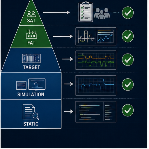
| Evidence layer | What it can prove | What it cannot prove by itself |
|---|---|---|
| static review | declarations, ownership, call references, style rules and obvious control-flow defects | runtime timing, I/O behavior or machine response |
| behavioral simulation | requirement logic over reproducible inputs, states and time assumptions | vendor compiler, exact instruction semantics, task/I/O scheduling or hardware |
| target compile/emulation | accepted syntax, target types, project structure and some runtime behavior | installed modules, wiring, final elements, process and safety |
| panel/FAT integration | configured hardware, panel I/O, devices, networks and integrated sequence under factory conditions | final installation, utilities, field wiring and actual process load |
| site/SAT/SIT | installed system behavior against site criteria | untested scenarios or future unauthorized changes |
Acceptance matrix for the worked example
The downloadable matrix contains 24 cases. The condensed view below shows the coverage model.
| Class | Cases | Key expected result |
|---|---|---|
| normal cycle | start lead, prove lead, add lag, stop and alternate | exactly one state owner; correct requests and next-lead update |
| threshold boundaries | 69.9/70.0%, 84.9/85.0%, 35.1/35.0% | declared inclusive comparisons and no threshold chatter |
| response timing | feedback before, at and after 3.0 s | target-documented timer boundary captured |
| availability | P1 unavailable, P2 unavailable, both unavailable | valid failover or fault; no request to unavailable equipment |
| quality | bad at idle, bad while running, restored | standard automatic requests removed; restart policy reapplied |
| simultaneous events | stop threshold and failure; lag threshold and lead failure | documented priority produces one deterministic result |
| restart | restart at every state and with feedback already true | outputs/state follow approved restart policy, not stale memory assumptions |
| call/timing | skipped module call, delayed feedback update, task overrun | defect is detected or the limitation is explicitly recorded |
| release | clean build, no unresolved forces, exact target identity, restore rehearsal | approved project can be attributed and recovered |
Use these downloads as editable starting evidence:
- Two-pump I/O and ownership contract (CSV)
- Two-pump IEC-style behavior oracle (ST)
- PLC programming acceptance matrix—24 tests (CSV)
Review code quality as behavior, not formatting
PLCopen’s Coding Guidelines recommend tailoring an applicable rule set to the organization and application, then using it in coding and review. The newer PLCopen software quality metrics guideline focuses on maintainability, reusability, testability, efficiency and reliability. A naming rule helps, but quality also depends on execution, interfaces, state, failure behavior and evidence.
| Review question | Strong evidence | Weak substitute |
|---|---|---|
| Is every routine executed? | task/program/call-tree report plus runtime observation | seeing the routine in the project tree |
| Who owns each command? | one declared writer and reviewed cross-reference | searching only for coil symbols |
| Are timers deterministic? | task period, invocation rule, preset units and boundary trace | assuming all TON implementations match |
| Can a mode race occur? | command authority/state table and simultaneous-event tests | an HMI color change |
| Does a fault explain the first failure? | latched first-out cause and captured command/feedback context | one generic “pump fault” bit |
| Is code portable? | target-by-target compile/adaptation record | IEC language name alone |
| Can the release be recovered? | offline backup, target identity and restore rehearsal | “latest” in a filename |
Commissioning and troubleshooting by the first disagreement
Troubleshooting becomes faster when the program exposes a chain of claims:
field condition → input electrical state → module/channel status
→ mapped raw tag → validated engineering tag and quality
→ request → permitted command → output/module/device command
→ actuator response → independent feedback → process result
Find the first adjacent pair that disagrees. If the field sensor is active but the module channel is not, inspecting a sequence transition is premature. If command is false, forcing the output hides the authorization defect. If command is true and the device receives nothing, the likely boundary is downstream of application logic.
| Symptom | Compare first | Likely classes—not a diagnosis | Evidence to capture |
|---|---|---|---|
| valid level never changes | field measurement vs raw channel and timestamp | instrument, loop power, wiring, channel config, scaling source | measured signal, channel status, raw count and configuration |
| level value is believable but stale | source timestamp/update counter vs consumer task | communication loss, skipped call, stale substitution | age, quality, connection state and task execution |
| request true, command false | mode/permissive/interlock/fault terms | ownership conflict, unavailable equipment, latched fault | complete authorization expression and first false term |
| command true, output channel false | logic tag vs mapped output/module status | mapping, connection, inhibit, force, module/channel fault | project mapping, force status, module diagnostics |
| output true, pump does not run | channel/device terminal vs starter/drive and protection | field power, protection, local mode, device fault, wiring | electrical measurements by qualified personnel and device diagnostics |
| pump runs, feedback false | physical response vs feedback circuit/input | auxiliary contact, drive status mapping, input wiring, debounce | observed rotation/flow, feedback source and input channel |
| unexpected lead selection | retained LeadPump and last completed-cycle event |
restart policy, multiple writer, incomplete-cycle interpretation | state history, writes/cross-reference and power-cycle trace |
| task/watchdog fault | measured task time vs configured period/watchdog | unbounded work, priority/pre-emption, blocking communication, unexpected path | max execution, overlap, event rate and last state |
Make online and field changes controlled and recoverable
An online edit is a production change, even if the IDE makes it convenient. Rockwell’s current Structured Text help distinguishes original, pending and test-edit views; other tools use different mechanisms. The engineering need remains the same: identify the controller and running source, assess impact, preserve a restore point, apply the smallest reviewed change, observe the defined window, accept or roll back, and reconcile the offline master.
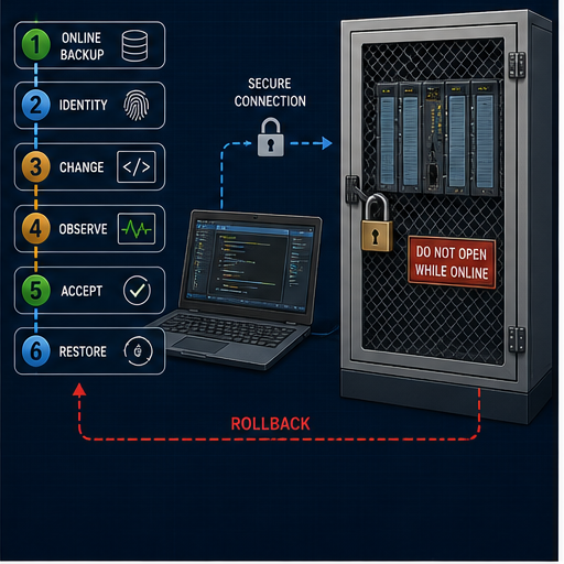
Minimum field-change record
| Field | Record before or during the change |
|---|---|
| asset identity | site, line, machine, panel and controller asset identifier |
| target identity | exact controller catalog/type, firmware/runtime, modules and network path |
| source identity | approved project/export, revision/hash, engineering-tool version and last download evidence |
| authorization | change request, risk/impact review, approver, execution window and responsible person |
| starting state | online comparison result, active modes/states, forces/overrides, faults and current backup |
| change | components touched, reason, predicted behavior and tests tied to requirement IDs |
| observation | inputs, state, command, feedback, process outcome and required observation duration |
| recovery | abort criteria, rollback steps, required operating state and restored-project proof |
| closeout | accepted version, updated offline master, test results, exceptions and handover |
NIST SP 800-82 Rev. 3 emphasizes that OT security must account for performance, reliability and safety requirements. Apply least privilege, controlled engineering access, segmentation, backup protection and monitoring in the context of the site’s OT-security program. Do not connect a programming workstation or controller to an enterprise network or the Internet merely for convenience.
Portability: preserve intent, then adapt the target
IEC 61131-3 gives a shared conceptual base. Portability still breaks at project configuration, supported subsets/extensions, libraries, memory and retentivity, I/O models, task scheduling, timer details, data representation, communication, safety and online-change behavior.
| Portability surface | What commonly changes | Adaptation evidence |
|---|---|---|
| project/resource model | configuration, device tree, programs, tasks and startup objects | rebuilt call tree and clean target build |
| types and literals | sizes, aliases, string/time support, conversion and overflow behavior | declaration audit and boundary tests |
| timers/counters/edges | invocation model, time base, reset, retentivity and one-scan flags | target manual references and trace at boundaries |
| I/O | address syntax, process image/update, quality/status and module configuration | exact module/channel map plus loop tests |
| libraries | function-block interfaces, versions, namespaces and instance memory | library manifest and interface tests |
| communications | connection model, byte order, update/timeout and diagnostics | data contract, packet/device evidence and loss/recovery tests |
| online change | permitted objects, state transfer, reset/download impact and access control | product procedure, rollback and observed state test |
| safety | certified toolchain, hardware, libraries, signatures and lifecycle | separate safety plan and validation; no inference from standard code |
Vendor examples illustrate the variance. Siemens publishes a Programming Guideline for S7-1200/S7-1500; Rockwell documents tasks, programs and routines; CODESYS documents its device/application/task/POU model. Use the document that matches the installed software and controller revision. A generic article cannot authorize a download or predict its operational impact.
PLC programming safety, reliability and cybersecurity boundaries
Standard PLC code can participate in ordinary control and diagnostics, but it is not automatically a safety function. Emergency stop, guard monitoring, burner management, overpressure protection, safe motion and other risk-reduction functions require appropriate risk assessment, architecture, components, systematic capability, validation and lifecycle controls. Never use this two-pump example to bypass physical protection, motor protection, local isolation or an engineered safety system.
| Boundary | Programming responsibility | Separate engineering responsibility |
|---|---|---|
| personnel safety | consume validated status where approved; avoid misleading HMI/diagnostic claims | hazard analysis, required risk reduction, safety architecture and validation |
| equipment protection | encode approved interlocks, timeouts and alarm evidence | device protection settings, coordination, mechanical/process limits |
| electrical work | expose useful command/status points | drawings, isolation, verification of absence of voltage and qualified work practices |
| process response | implement approved thresholds and sequences | process design, relief/containment, hydraulic/thermal calculations and operating procedures |
| cybersecurity | minimize data/control interfaces and support attribution | identity, remote access, segmentation, patch/backup and incident-response program |
| availability | deterministic state/restart and first-out diagnostics | redundancy, spares, recovery objectives and operational contingency |
A practical learning and project path
Learn PLC programming in the same order that a reliable project is built. Starting with hundreds of unrelated instructions creates recognition, not engineering judgment.
- Boolean and scan behavior: implement a stop-dominant motor request, trace at least six scans and test simultaneous start/stop.
- I/O contracts: map simulated field inputs into typed names with clear true-state meaning, quality and one writer.
- State and time: add TON/TOF/pulse behavior, counters and edge detection; test one scan below/at/above every boundary.
- Equipment modules: separate request, command, feedback, availability, timeout, fault and reset.
- Sequences: build a small state machine with abnormal, abort, hold and restart paths.
- Analog/process data: scale raw values with units, quality and range checks before attempting PID.
- Target workflow: create the real project, configure its task and I/O, compile, record versions and reproduce tests.
- Commissioning: prove the chain from field condition to input to logic to output to feedback, under authorized procedures.
- Maintenance: diagnose by first disagreement, make controlled changes and rehearse restoration.
After you can explain the two-pump trace without looking at the code, use the PLC programming exercises, real-world PLC examples and troubleshooting guide to widen the failure surface.
Practise the behavior with an explicit evidence boundary
PLC Programming IO and PLC Simulation Software share the same operator. The simulator path below is a product-owned practice environment, not an independent endorsement.
Open the PLC programming evidence lab
Use it to practise discrete logic, state, timing, fault injection and repeatable acceptance cases before using a vendor target. It does not reproduce your controller project, compiler, firmware, task priority, I/O refresh, module electronics, network, instrument, drive/starter, motor, hydraulic process or safety system. Measure this CTA through evidence-lab start, completed test, registration, paid signup and retained use—not click-through alone—so a lower-volume but higher-quality path is not removed merely because another button receives more clicks.
Specialist routes after the fundamentals
Move from this broad workflow to the exact implementation task: CODESYS Structured Text, Structured Text loops and control flow, CX-Programmer function blocks, or Siemens function blocks in TIA Portal. Use the industrial automation systems guide when the task expands from one PLC program to architecture, and the PLC program testing guide when release evidence is the priority. For controller selection, compare the PLC brand and hardware shortlist, then use a vendor owner such as the Unitronics PLC programming guide for exact software, I/O and troubleshooting boundaries.
Answer map for search and AI-assisted PLC questions
| Natural-language question | Short, citable answer | Best section |
|---|---|---|
| What is PLC programming? | Converting industrial requirements into scheduled controller logic, typed data, commands, diagnostics and testable release evidence | PLC programming in one precise answer |
| How do I program a PLC from scratch? | Define testable behavior, freeze I/O/data, design execution and ownership, implement, simulate, compile for the exact target, then FAT/SAT and release | end-to-end workflow |
| Which PLC language should I learn first? | Start with LD for observable discrete logic, then add ST for algorithms/state; choose by work context and target support | choose languages by responsibility |
| Is Ladder Logic still used? | Yes; LD remains one of the graphical languages specified by IEC 61131-3:2025 and is useful for discrete authorization paths | language selector |
| Is Instruction List still one of the current IEC languages? | The 2025 IEC description names ST, LD and FBD, with SFC structuring elements; treat older IL material as legacy and check the target | direct answer |
| Can one PLC project mix LD and ST? | Yes, when the target supports both and interfaces, state ownership, execution and review rules stay explicit | language responsibility map |
| What is the difference between a PLC request and command? | A request expresses desired action; a command is the PLC’s authorized result after modes, interlocks and faults | terminology and I/O contract |
| Why is feedback separate from the output command? | Feedback independently proves the device or process responded; a true command proves only software intent | worked pump example |
| Does a simulator prove a PLC program will work on hardware? | No; it can prove modeled behavior, while target, I/O, wiring, device, process and safety evidence require later layers | verification pyramid |
| How do I test a PLC timer? | Test one scan before, at and after its preset with the actual task and target instruction semantics | acceptance matrix |
| Why is my PLC routine not running? | Confirm it is assigned to a scheduled program/task and reached through the call tree before debugging its internal logic | execution architecture |
| How should PLC code be organized? | Separate input validation, modes, equipment, sequence, communications and diagnostics with explicit task/call/data ownership | workflow and architecture |
| How do I troubleshoot PLC logic? | Compare adjacent boundaries from field state through input, tag, request, command, output, feedback and process result | first-disagreement method |
| Are IEC 61131-3 programs portable? | Concepts and some source may transfer, but target configuration, dialect, libraries, runtime, I/O and online behavior need adaptation | portability section |
| How do I safely make an online PLC change? | Follow site authorization, backup and identify the running source, bound the change/test, observe, accept or restore, and reconcile the master | controlled field changes |
| What should a PLC release contain? | Approved source/project, target and tool identity, I/O/configuration, build result, tests, exceptions, backups and recovery instructions | release workflow |
Frequently asked questions
What is PLC programming in simple terms?
PLC programming is writing and testing the control behavior for an industrial controller. The controller reads configured inputs, evaluates scheduled logic and produces commands, while the program also records state, faults and evidence so the controlled equipment can be operated and diagnosed.
What are the PLC programming languages in IEC 61131-3:2025?
IEC 61131-3:2025 Edition 4 specifies Structured Text, Ladder Diagram and Function Block Diagram. It also defines Sequential Function Chart elements for structuring programs and function blocks. Product support and vendor extensions still vary.
Which PLC programming language should a beginner start with?
Ladder Diagram is a useful first language for simple Boolean control because contacts, branches and coils make the authorization path visible. Add Structured Text early for types, calculations and explicit state logic rather than trying to force every responsibility into ladder.
Is PLC programming the same as ordinary software programming?
They share types, modularity, testing and change control, but PLC software is tightly coupled to scheduled execution, I/O electronics, networks, actuators and physical hazards. Restart, stale data, response time and online change therefore require unusually explicit treatment.
What is the PLC scan cycle?
“Scan” usually describes repeated controller work, but the exact model depends on the platform and configuration. Inputs, programs, outputs and communications may update in different schedules, while periodic or event tasks can pre-empt other work. Verify the target manuals and measure the configured project.
Can I learn PLC programming without physical hardware?
Yes. A simulator can teach Boolean logic, state, timers, fault injection and test discipline. It cannot validate target compilation, module behavior, wiring, network timing, the physical process or functional safety, so hardware and site evidence remain later steps.
What is the difference between a PLC program, function and function block?
A program is normally scheduled within a resource/task context. A function returns a result without the same instance-state model, while a function block has instances that can retain internal state. Exact declaration and calling behavior must be checked in the chosen IEC implementation.
Why should PLC commands have one writer?
One writer creates a single place where command priority and authorization are decided. Multiple coils or assignments can make the final value depend on execution order and obscure which subsystem controlled the equipment, increasing commissioning and maintenance risk.
How do you test a PLC program before commissioning?
Start with static review and deterministic behavioral cases, then compile and test the exact target project, integrate panel hardware at FAT, and verify the installed system at SAT/SIT. Preserve inputs, state, command, feedback and outcome for every requirement and exception.
What makes a PLC program maintainable?
Clear requirements, typed interfaces, stable naming, modular responsibilities, explicit task/call structure, one writer per command, visible state, first-out diagnostics, automated or repeatable tests, controlled versions and a proven restore path make PLC software maintainable.
Why does a PLC output turn on when the rung looks false?
Possible causes include another writer, a force/override, different execution order, a stale online view, an alias/mapping error, retained state or logic in another task. Confirm the physical output, module status, mapped tag, force state, cross-reference and live task/call path in that order.
Can IEC 61131-3 code be copied between PLC brands?
Some algorithms and interfaces can be adapted, but copy-and-run portability should not be assumed. Vendor syntax, libraries, tasks, memory, timers, I/O, safety, communication and project formats differ. Rebuild the target configuration and repeat all boundary and integration tests.
Is PLC simulation enough for a safety function?
No. Generic simulation may support learning or behavioral test preparation, but it does not establish the required safety lifecycle, hardware architecture, toolchain qualification, systematic capability or validation for a safety function.
What should I back up before changing a PLC online?
Capture the running controller identity and configuration, upload or otherwise preserve the current project according to the vendor/site procedure, record tool and firmware versions, compare online/offline state, document forces and modes, and test that the restore path is usable before the change window.
Official sources, review date and limitations
This article was technically reviewed on 31 August 2026. Direct primary and official sources:
- IEC 61131-3:2025 Edition 4—Programming languages
- IEC 61131 series catalogue, including current parts
- PLCopen: recognizing an IEC 61131-3 programming system
- PLCopen Coding Guidelines version 1.0
- PLCopen Guideline on Software Quality Metrics version 1.0
- PLCopen: Structuring Program Development with IEC 61131-3
- PLCopen software and training guidelines
- Rockwell: Logix 5000 Controllers Tasks, Programs, and Routines
- Rockwell Studio 5000: use tasks, programs and routines
- Rockwell Studio 5000: current instruction-set help
- Rockwell Studio 5000: Structured Text online editing
- Siemens: Programming Guideline for S7-1200/S7-1500
- Siemens: Programming Guideline Safety for S7-1200/S7-1500
- CODESYS: Task Configuration
- NIST SP 800-82 Rev. 3—Guide to Operational Technology Security
The exact standard text may require purchase. This article summarizes only public scope descriptions and official guidance; it is not a substitute for the controlled standard, vendor manuals, project specifications, risk assessment, electrical drawings, safe-work procedures or competent engineering review. Thresholds, timing and state policy in the example are explicit teaching assumptions. Before using any pattern on equipment, verify the exact controller, firmware/runtime, engineering software, task and I/O configuration, instruction semantics, communications, devices, process and safety requirements, then execute authorized FAT/SAT and recovery tests.