PLC Programming: Languages, Examples & How It Works
PLC programming is the work of translating a machine or process requirement into deterministic control logic. A PLC samples field inputs, executes scheduled logic, updates outputs and performs communications and diagnostics repeatedly, while the program applies permissives, interlocks, sequences, timing and fault handling.
In practical terms, PLC programming turns a written control requirement into logic that reads sensors and commands actuators in a predictable cycle. The programmer defines what may run, what must stop, how a sequence advances, what happens after a fault, and how operators and maintenance teams can diagnose the result.
This guide is the broad starting point. Use its linked language, software, example, protocol, application, vendor and career guides when you need implementation detail.
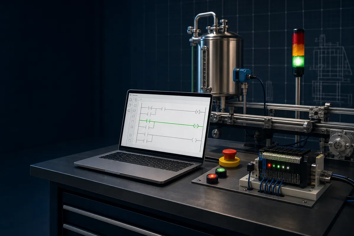
How PLC programming works: the scan-cycle mental model
A useful first model is inputs → logic → outputs → housekeeping:
- Read inputs. The controller receives the state or value of connected devices such as pushbuttons, limit switches, proximity sensors, pressure transmitters and remote I/O.
- Execute scheduled logic. A task invokes programs, routines or program organization units. Boolean logic, timers, counters, calculations and function blocks produce new internal states and output commands.
- Update outputs. The output image or equivalent command data is transferred toward relays, contactors, valves, drives, lamps and other devices.
- Perform system work. Communications, diagnostics and operating-system services run alongside or between user tasks.
This is a mental model, not a promise that every controller performs one simple synchronous loop. Modern controllers can have periodic and event tasks, asynchronous communications, remote-I/O update intervals and immediate-I/O instructions. Read the target controller’s scheduling and I/O documentation before making timing assumptions.
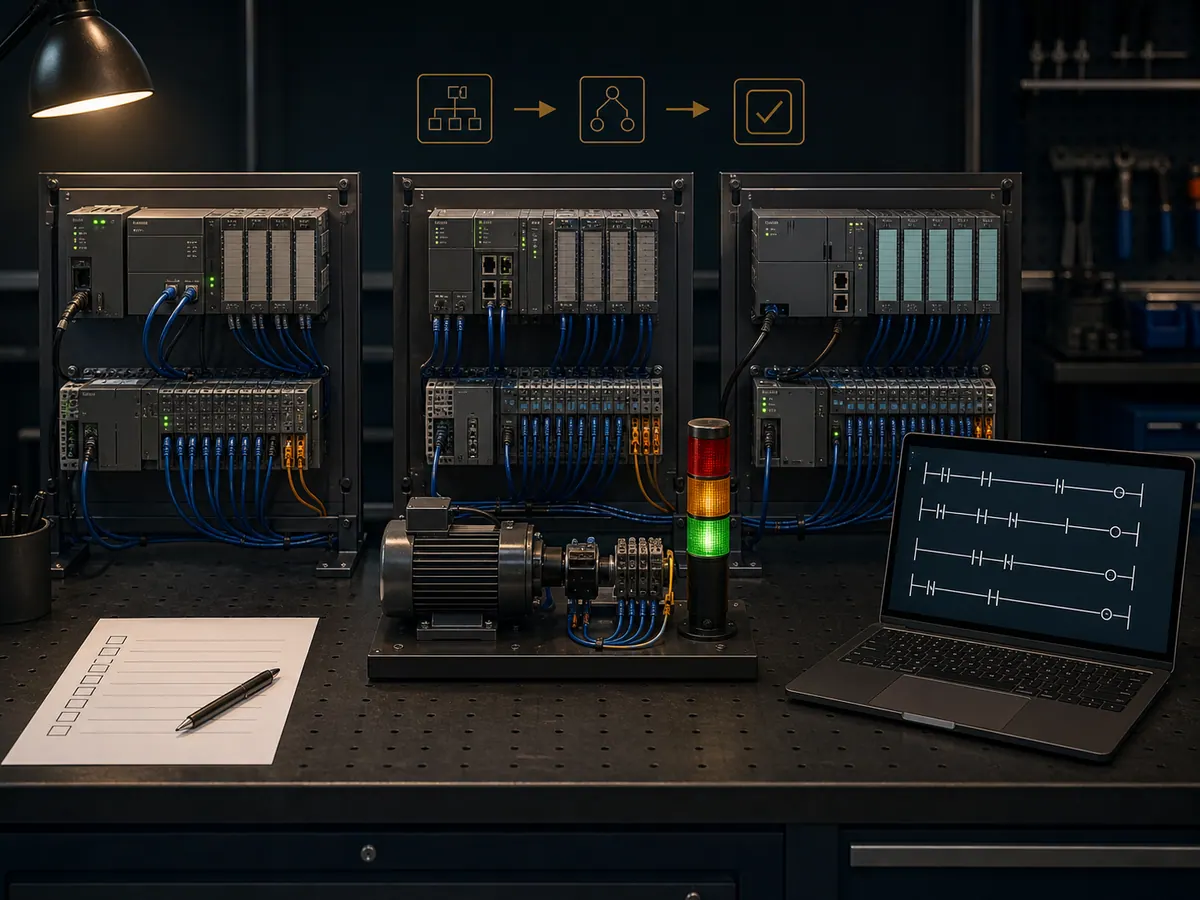
Hardware and I/O context programmers need
PLC programming is not just drawing contacts or writing expressions. Each program variable must have an engineering meaning and a trustworthy source:
| Layer | Example | Programming question |
|---|---|---|
| Input device | Start pushbutton, level switch, 4–20 mA transmitter | Is the signal normally open, normally closed, scaled, filtered or diagnosed? |
| Input channel | Local digital input or remote analog input | What address/tag receives it, and how often can it update? |
| Program state | Permissive, sequence step, fault latch | Is the value transient, retained, derived or reset deliberately? |
| Output command | Motor run request, valve-open request | Which interlocks must dominate the command? |
| Output device | Contactor, VFD, solenoid or control valve | What feedback proves the physical action occurred? |
Separate command from feedback. A true motor command does not prove that the motor is turning; auxiliary contact, drive-ready/running status, current or process feedback may be needed. Similarly, a valve command does not prove position. Good PLC logic detects the difference and defines the response.
For a deeper treatment of input images, execution and output updates, read the PLC scan-cycle guide. For address and tag conventions, use the PLC addressing guide.
PLC programming languages in IEC 61131-3:2025
The current international reference is IEC 61131-3:2025, Edition 4. The IEC record describes Structured Text (ST), Ladder Diagram (LD), Function Block Diagram (FBD), and Sequential Function Chart (SFC) elements used to structure programs and function blocks. Instruction List is a legacy language and is not in the current Edition 4 suite. See the official IEC 61131-3:2025 publication record and our focused IEC 61131-3 standards guide.
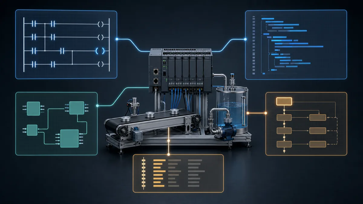
| Representation | Strong use case | Watch for |
|---|---|---|
| Ladder Diagram (LD) | Discrete conditions, permissives and maintenance-visible interlocks | Dense arithmetic, loops and oversized rungs |
| Structured Text (ST) | Calculations, arrays, loops, state logic and reusable algorithms | Hidden side effects and long monolithic blocks |
| Function Block Diagram (FBD) | Signal flow, analog conditioning and interconnected control blocks | Crossing connections and unclear execution order |
| SFC elements | Explicit steps, transitions and actions in sequences | Incomplete abort, hold, restart and recovery behavior |
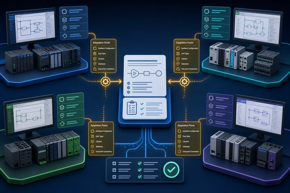
The language names transfer between ecosystems; exact instructions, libraries, scheduling, data types, project files and safety rules do not. Rockwell’s own Logix programming-language guidance explains platform-specific language uses and restrictions. Treat vendor documentation as authoritative for the controller and firmware being commissioned.
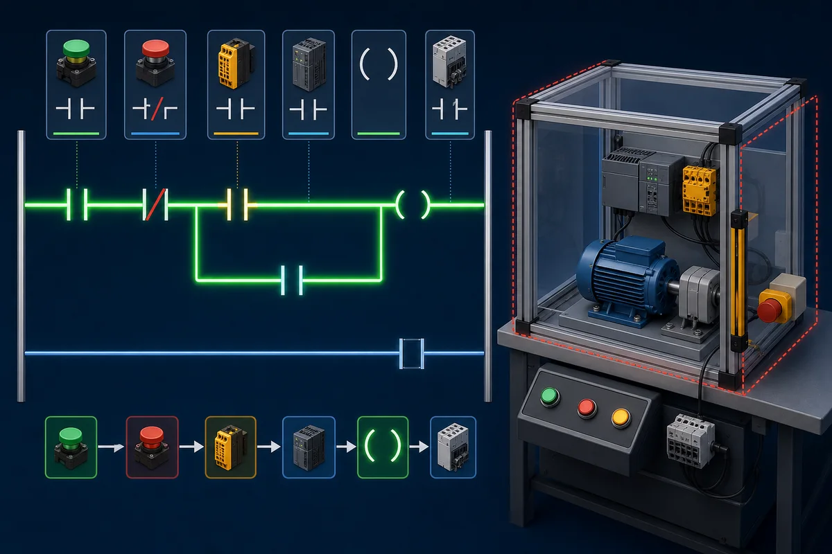
One matched motor start/stop example
Use one written requirement before comparing languages:
- pressing Start requests the motor to run;
- pressing Stop removes the run request;
- an overload fault prevents or removes the request;
- Stop and overload dominate Start when signals occur together;
- the output command follows the validated latched request.
These teaching examples express the same Boolean state update. They have not been claimed as an executable vendor project. Contact syntax, evaluation order, feedback connections and variable assignment must be recreated and tested in the chosen engineering environment.
| Variable | Type | Meaning |
|---|---|---|
StartPB |
BOOL | TRUE while the start command is present |
StopPB |
BOOL | TRUE while stop is requested |
OverloadFault |
BOOL | TRUE while the overload fault is present |
RunCmd |
BOOL | Internal latched run request |
MotorOut |
BOOL | Output command after the request is validated |
Ladder Diagram representation
|----[/ StopPB ]----[/ OverloadFault ]----+----[ StartPB ]----( RunCmd )----|
|                                         |                                 |
|                                         +----[ RunCmd ]--------------------|

|----[ RunCmd ]--------------------------------------------( MotorOut )-------|
The parallel StartPB/RunCmd branch is the seal-in path. StopPB and OverloadFault conditions are outside that branch so either removes the latch.
Structured Text representation
RunCmd := (StartPB OR RunCmd)
          AND NOT StopPB
          AND NOT OverloadFault;

MotorOut := RunCmd;
The assignment makes Stop and overload dominant because both must be false for RunCmd to remain true. In production code, define initialization, restart behavior, task context and diagnostic handling explicitly.
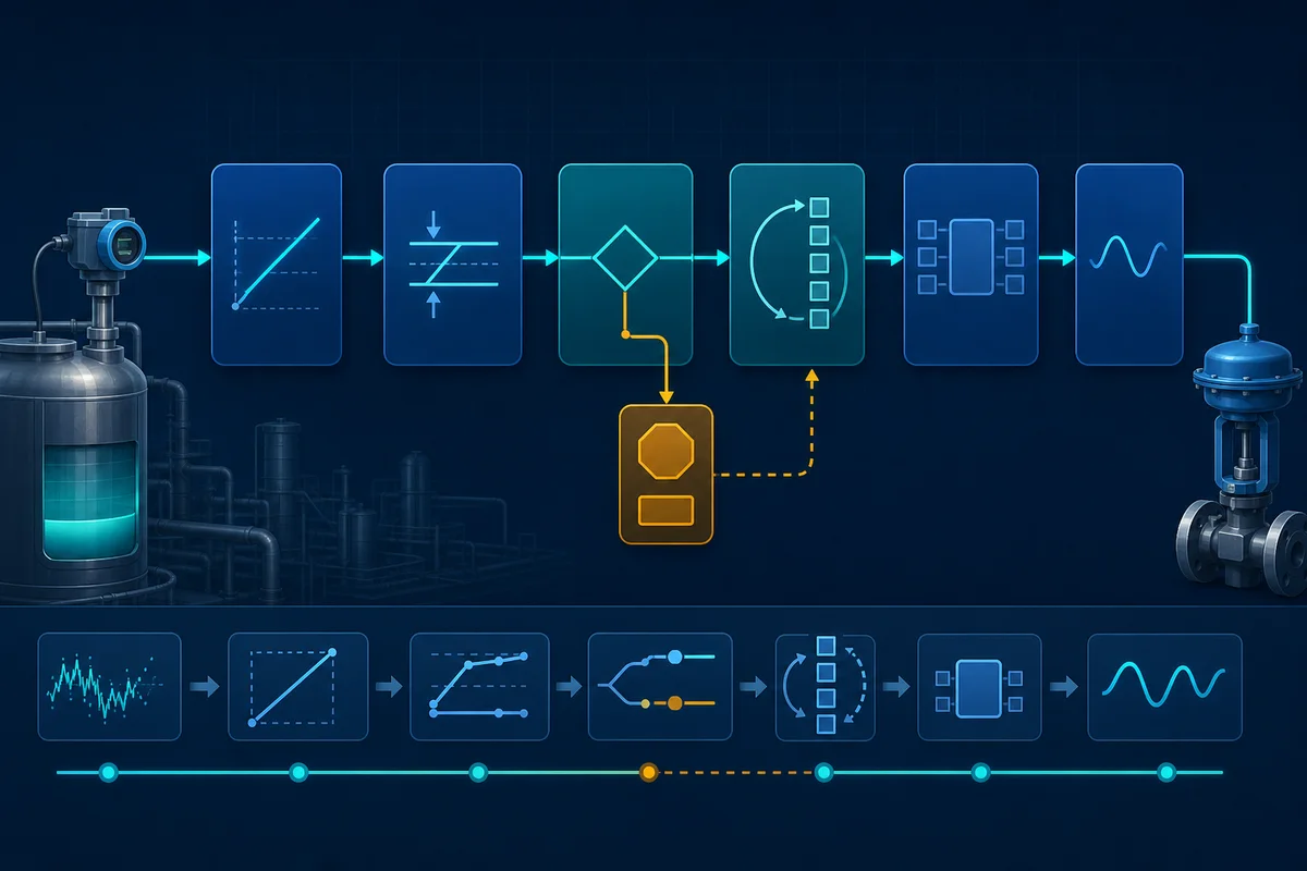
Function Block Diagram representation
StartPB ---------                  OR ----RunCmd ----------/                                   AND ---- RunCmd
NOT StopPB --------------/
NOT OverloadFault -------/

RunCmd -------------------------- MotorOut
In an actual FBD editor, use the documented OR, NOT and AND elements and an explicit feedback path or an approved stateful block. Confirm evaluation and initialization behavior in that tool rather than treating this text sketch as importable FBD.
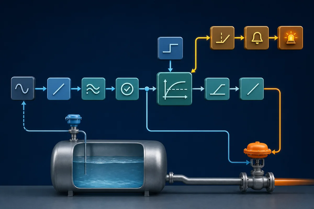
Test cases shared by all three representations
| Case | Initial RunCmd |
Start | Stop | Overload | Expected RunCmd after evaluation |
|---|---|---|---|---|---|
| Idle | FALSE | FALSE | FALSE | FALSE | FALSE |
| Start | FALSE | TRUE | FALSE | FALSE | TRUE |
| Seal in | TRUE | FALSE | FALSE | FALSE | TRUE |
| Stop | TRUE | FALSE | TRUE | FALSE | FALSE |
| Overload | TRUE | FALSE | FALSE | TRUE | FALSE |
| Start and Stop together | FALSE | TRUE | TRUE | FALSE | FALSE |
| Start while faulted | FALSE | TRUE | FALSE | TRUE | FALSE |
This truth-oriented table is more portable than any one drawing. Add tests for power-up, task restart, I/O failure, feedback timeout and fault-reset policy before adapting the pattern to a real machine. The motor start/stop tutorial expands the circuit; the PLC programming examples library covers larger applications.
How programs are organized across IEC, Siemens and Rockwell
“Program,” “function” and “block” do not map one-to-one between platforms. Keep the control requirement separate from the vendor container:
| Ecosystem | Scheduling and containers | Stateful reuse and data |
|---|---|---|
| IEC/CODESYS | A task configuration calls program POUs; programs can call functions and function blocks | Function-block instances retain state; applications contain global and local data |
| Siemens S7 in TIA Portal | Organization blocks (OBs) provide execution entry points and call FBs and FCs | FBs use instance data blocks; FCs do not have an FB instance DB; global DBs hold shared data |
| Rockwell Logix 5000 | Tasks schedule programs; programs contain routines | Add-On Instructions package reusable logic; tags can have controller or program scope |
The CODESYS Development System overview identifies IEC 61131-3 application development and supported editor forms. Siemens documents its current block and programming workflow in the official Programming a PLC in STEP 7 guidance. Rockwell documents tasks, programs, routines and supported language behavior in its Logix controller programming guidance.
A maintainable organization pattern
For a machine or process unit, organize around responsibilities rather than collecting unrelated rungs:
- I/O mapping and normalization: convert raw addresses and analog counts into named engineering signals.
- Device modules: define commands, permissives, interlocks, feedback and diagnostics for each motor, valve or instrument.
- Sequence or state control: coordinate devices into operating modes and production steps.
- Alarm and event logic: detect abnormal conditions, latch where required, timestamp and define reset criteria.
- HMI interface: expose commands and status without letting display code bypass equipment rules.
- Communications: map produced/consumed, fieldbus or supervisory data at a deliberate boundary.
Use one writer for critical state where practical, document retained values, and make reset/restart behavior explicit. A useful comment explains why a decision exists or cites a requirement; it should not merely restate the instruction.
Choosing PLC software and a simulator
Start with the target, not a generic “best software” ranking:
| Goal | Correct starting point |
|---|---|
| Commission a known Siemens, Rockwell, Mitsubishi, Omron, Schneider or other PLC | The manufacturer-supported engineering environment for the exact controller and firmware |
| Develop for a CODESYS-based device | The device vendor’s supported CODESYS package, runtime and version |
| Learn IEC concepts without assigned hardware | A simulator or training environment with editable logic, observable I/O and repeatable tests |
| Validate native project compatibility | The exact vendor tool and version used by the owner or machine builder |
| Test safety, motion or hardware behavior | The approved engineering tool plus the target hardware and documented validation process |
Native project files, hardware catalogues, firmware support, online diagnostics, safety options and licensing are decisive. Compare those boundaries in the PLC programming software guide, then use the appropriate Siemens programming tutorial, Rockwell Logix tutorial, CODESYS guide or OpenPLC tutorial.
Disclosed browser practice path
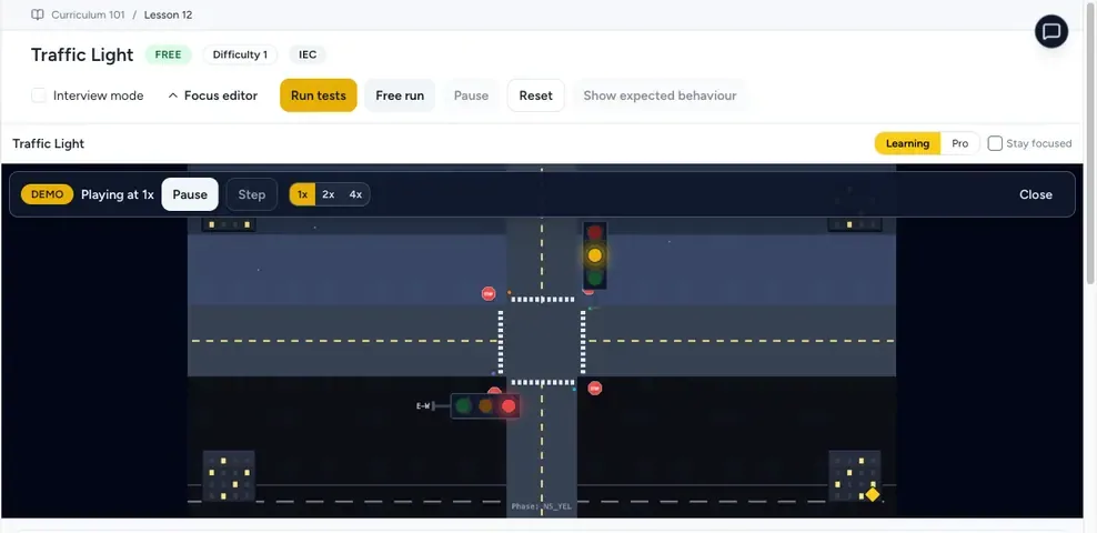
PLC Simulation Software is a browser-based learning and prototyping simulator operated by the same publisher as plcprogramming.io. Its versioned product facts record a non-expiring free account with no credit card, 12 core lessons, 6 free lessons per listed dialect, 8 listed learning dialects and 140 source-catalogued practice records; visible lesson and scenario access can be lower because it varies by account state, plan, entitlement and rollout.
Use it to edit logic, observe simulated I/O and repeat small exercises before moving into the target vendor tool. It is not a production PLC, a substitute for hardware testing, or an exact emulator of every vendor instruction and firmware behavior. Native vendor project-file export is not guaranteed.
Testing, simulation and commissioning
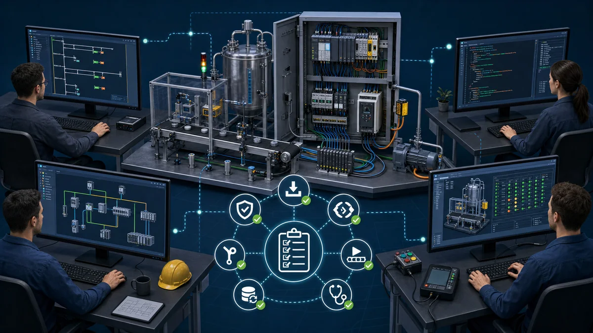
Programming is incomplete until behavior has been checked against requirements. Build a test matrix before energizing equipment:
- normal start, run and stop;
- every permissive false in isolation;
- every interlock or trip;
- sensor stuck on, stuck off and implausible analog values;
- command without expected feedback;
- power cycle, task restart and retained-state behavior;
- communications loss and recovery;
- manual, automatic, local and remote mode boundaries;
- sequence abort, hold, restart and recovery;
- simultaneous or badly timed operator commands.
A simulator can expose state and sequencing errors. Emulation can reproduce more of a target runtime when the vendor supports it. Neither proves wiring polarity, field-device behavior, electrical noise, network timing, drive configuration, process dynamics or every firmware-specific instruction.
Safety boundary
Do not treat an ordinary PLC bit as the sole risk-reduction measure for an emergency stop, guard, light curtain or other safety function. Safety functions require a hazard/risk assessment, suitable architecture and components, verified wiring, validated safety logic and documented testing under the applicable standards and site procedures. Standard control logic can coordinate production behavior, but it must not bypass the independent safety design.
During commissioning, use an approved method statement, controlled access, energy isolation where required, force/jumper management, peer review and recorded test results. Never infer that a clean simulation authorizes energizing a machine.
A practical PLC programming learning path
Progress by producing evidence, not by collecting disconnected syntax:
- Trace the control loop. Identify an input device, its program tag, the logic decision, the output command and the feedback.
- Learn Boolean Ladder. Build start/stop, permissive and interlock logic, then test every input combination.
- Add timers, counters and analog values. Define time bases, reset behavior, limits, scaling and fault cases.
- Rewrite one requirement in ST and FBD. Compare behavior with the same test table rather than comparing appearance.
- Create a small state machine. Implement an idle/run/fault or fill/mix/drain sequence with explicit recovery.
- Move to a vendor ecosystem. Learn its task model, hardware configuration, tags, diagnostics, upload/download and version boundaries.
- Build a portfolio package. Include the requirement, I/O list, state diagram, code, test matrix, captured results, change record and known limitations.
- Transfer to supervised hardware. Verify wiring, device behavior, communications, timing, abnormal cases and safe commissioning practice.
The beginner PLC programming path turns these stages into a first project. The PLC programming language comparison goes deeper on LD, ST, FBD and SFC. For deliberate practice, use the PLC training hub, and for credential decisions use the certification and career guide.
Where PLC programming is used
The same core model appears across applications, but the engineering priorities change:
- Discrete manufacturing: machine states, interlocks, motion coordination and cycle diagnostics.
- Process systems: analog scaling, control loops, sequences, alarms and operator modes.
- Material handling: routing, accumulation, tracking, jam detection and safe restart.
- Utilities and infrastructure: availability, remote I/O, telemetry, redundancy and controlled recovery.
- Building and energy systems: equipment staging, schedules, alarming and supervisory integration.
Explore complete patterns in the real-world PLC applications pillar, then study industrial communications for the networks that connect controllers, drives, remote I/O, HMIs and supervisory systems.
PLC programming checklist
Before calling a routine finished, confirm:
- the written requirement and abnormal cases are unambiguous;
- every I/O tag has a source, polarity, range, update behavior and failure response;
- commands, permissives, interlocks, trips and feedback are separate concepts;
- task rates and execution order are documented where behavior depends on them;
- reset, retention, power-up and communications recovery are tested;
- reusable blocks have defined interfaces and no hidden dependencies;
- diagnostics explain why an action is prevented or failed;
- test results trace back to requirements;
- safety functions are handled by the approved safety lifecycle;
- the archived project, software version, controller firmware and change record can be reopened by another engineer.
PLC programming becomes transferable when requirements, state, I/O, tests and limitations are explicit. Learn the vendor syntax, but preserve that engineering model across every platform.
Continue Learning
Dive Deeper into Languages
Ladder Logic Complete Tutorial
Visual electrical-style language for binary logic and interlocks
Structured Text Programming Guide
Text-based language for complex algorithms and math
Function Block vs Ladder Logic
When to choose which language for your application
Ladder Logic Symbols Complete Guide
Contact, coil, and branch symbols explained
Foundational Concepts
Frequently Asked Questions
Which PLC programming language should a beginner start with?
Start with Ladder Diagram when your goal is discrete machine control or maintenance because its condition path resembles relay logic. Add Structured Text for calculations, arrays, loops and reusable algorithms. Confirm the language support and restrictions in the engineering software for the controller you will actually use.
Are IEC 61131-3 languages portable between vendors?
The requirements, Boolean logic, state models and test cases can transfer, but native projects generally do not. Instructions, data types, libraries, scheduling, I/O, safety rules and file formats vary by vendor and version. Recreate and validate the behavior in the supported target environment.
Should I learn structured text if I already know ladder?
It is useful when you need calculations, loops, arrays, string handling or compact state logic. Keep Ladder for requirements that are clearer as visible condition paths. The right mix depends on the controller, safety restrictions, team review practices and maintainability needs.
Is Sequential Function Chart (SFC) worth learning?
Learn SFC elements when a sequence is naturally described as named steps, transitions and actions. It can make batch and machine states explicit, but abort, hold, restart and recovery behavior still need careful design and testing. A plain state machine may be clearer on platforms with limited SFC support.
Is Instruction List (IL) still relevant?
Only for legacy maintenance. IEC 61131-3 Edition 3 marked IL as deprecated, and the current 2025 Edition 4 removed it from the language suite. New projects use structured text instead. Learn IL only when you need to read older vendor projects such as Siemens STL-based code.
Can I program a PLC entirely in one language?
Some platforms permit an entire project in one language, but support and restrictions vary. Choose the representation that makes each requirement easiest to review and test: Ladder for visible Boolean paths, Structured Text for algorithms and data, FBD for signal flow, and SFC elements for explicit sequences.