Watchdog Timer in Siemens PLCs: S7 Cycle Time, OB80 and Diagnosis
Configure and diagnose Siemens S7-1200/S7-1500 cycle monitoring with exact CPU evidence, OB80 first-out capture, RT_INFO and RUNTIME measurements, bounded loop repair and controlled recovery.
Review status: Editorially reviewed against current Siemens STEP 7 V21 S7-1200/S7-1500/S7-1200 G2 cycle, cyclic-OB, OB80, RE_TRIGR, RT_INFO, RUNTIME, diagnostics-buffer and Safety documentation plus the current S7-1200 V4.6 system manual; exact CPU, firmware, CPU family, redundancy/safety status, OB structure, limits, measured timing, fault reaction, output/device behavior and approved recovery require target-specific verification
Direct answer
The main watchdog timer in a Siemens PLC is usually configured as the CPU's maximum cycle time or cycle monitoring time—not as a TON instruction. On a standard S7-1200 or non-redundant S7-1500, the operating system monitors cyclic-program execution. When the cycle crosses the configured maximum, it records a diagnostic event and attempts to start the time-error organization block OB80. If the relevant OB80 is absent, the CPU can enter STOP. If the maximum is exceeded a second time in the same program cycle, the CPU can enter STOP even when OB80 exists.
That event proves a timing boundary was crossed; it does not identify the cause. Preserve the diagnostics-buffer entry, CPU/firmware, program-cycle configuration, current/minimum/maximum timing, faulting OB/start information, recent changes and triggering data before clearing or downloading. Then use STEP 7 Online tools for the whole-cycle view, RT_INFO for OB and cycle statistics, and RUNTIME to bracket suspect code. Reproduce the problem on an isolated target or approved test setup, fix the execution path or schedule, and repeat worst-case load and restart tests.
Do not increase the maximum cycle time merely to keep the CPU in RUN. The threshold should protect the process response requirement with measured margin. A larger value changes when a timing failure is detected; RE_TRIGR restarts cycle monitoring and can mask an oversized execution path if used casually. Both changes require the same design and risk review as code or scheduling changes.
This page focuses on current S7-1200 and S7-1500 standard-program cycle supervision. The PLC scan-cycle and watchdog guide remains the cross-vendor owner. F-runtime-group monitoring, redundant S7-1500 R/H behavior, S7-300/400 legacy start information, network watchdogs and process timeouts have separate semantics and must not be inferred from this standard-cycle example.
Download the Siemens watchdog design and evidence register, 16-test acceptance matrix and bounded SCL example before changing the CPU property or fault handler.
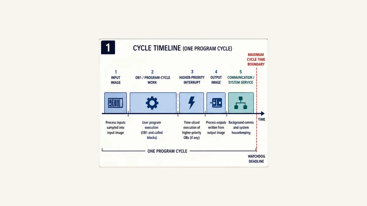
Identify the exact Siemens timing layer
Maximum cycle time is not a TON
A TON is user logic. It is evaluated only while its calling OB and block path execute. If the cyclic program is trapped in a long loop before reaching the timer call, that timer cannot reliably supervise the stalled execution context. Use a process timer for requirements such as “running feedback must arrive within five seconds”; use CPU cycle monitoring for “the cyclic program must complete before this execution boundary.”
| Timing mechanism | Supervises | Owner | Typical failure evidence | Not proved by it |
|---|---|---|---|---|
| CPU maximum cycle time | cyclic program execution and product-defined included work | S7 operating system and CPU configuration | diagnostics entry, OB80 start event, STOP outcome | which routine or data caused the time |
| cyclic-interrupt scheduling | whether a configured OB is requested and completed according to its event rules | CPU scheduler/OB configuration | OB runtime, overlap/queue/time-error evidence | overall OB1 cycle alone |
| F-runtime-group monitoring | certified safety-program call/runtime boundary | Safety configuration and certified runtime | F-diagnostic and STOP/maintenance behavior | standard OB80 design or ordinary process timeout |
| network/device watchdog | cyclic communication update | interface/device stack | quality, status, timeout and device diagnostics | user-program execution time |
application TON timeout |
expected application event | PLC program | request/feedback state and timer result | CPU/runtime health |
| HMI heartbeat age | freshness of exchanged data | communication application | last-change/receive age and quality | PLC cyclic response margin |
Name the layer in every incident. “S7-1500 CPU 151x, firmware x, program-cycle maximum 40 ms, OB80 start event after an observed 43 ms cycle” is actionable. “The Siemens watchdog failed” is not.
Standard, redundant and failsafe CPUs are not interchangeable
Siemens' current S7-1500 manual collection gives a standard non-redundant default maximum cycle time of 150 ms and a configurable range of 1–6000 ms. Do not copy that range to every S7-1200 generation, S7-1500 R/H system, software controller, drive controller or F-runtime group. Each has its own CPU/firmware manual and response model.
An F-runtime group has certified monitoring parameters tied to safety reaction-time calculations. Siemens recommends specific F-OB scheduling practices and defines a maximum group cycle separately. Extending an ordinary program cycle or calling RE_TRIGR does not modify those certified calculations in a safe or automatic way. Safety changes require the Safety project, signatures, response-time calculation and validation.
Create a compatibility manifest before diagnosis:
| Surface | Record | Why it changes the answer |
|---|---|---|
| CPU | exact order number and standard/F/R/H/software-controller class | limits and fault behavior differ |
| firmware | as-found and intended revision | instruction and diagnostics behavior can change |
| STEP 7 | TIA Portal edition/version/update and project compatibility | available properties, block interfaces and help are versioned |
| cyclic architecture | every program-cycle OB, cyclic interrupt, priority and call chain | total cycle includes more than one visible OB1 routine |
| maximum cycle property | configured value, default provenance and change history | the trip boundary is a project setting |
| OB80 | present/absent, optimized or legacy start information, code revision | determines first time-error handling and evidence |
| measurement | Online tools, CPU display/Web server, RT_INFO, RUNTIME, trace |
each observes a different layer |
| output behavior | CPU, module/device, network and application reaction | STOP does not justify a universal field-state claim |
| safety/redundancy | F-runtime groups and R/H status | requires product-specific response and timing rules |
How Siemens cycle monitoring works
The monitored cycle contains interruptions and system work
Current S7-1500 documentation describes cycle time as cyclic program runtime including nested higher-priority OB execution and applicable operating-system work. If more than one program-cycle OB is configured, each contributes. The process image, communication, diagnostics and other services have their documented places in CPU execution. Cycle time therefore varies from one pass to the next.
Minimum cycle time is a different setting. Where configured, the operating system can delay the next cycle start until the minimum has elapsed and use the waiting period for events and services. A stable 20 ms observed cycle can therefore be a deliberately delayed minimum rather than 20 ms of user-code execution.
Distinguish these quantities:
| Quantity | Question | Common mistake |
|---|---|---|
| current cycle time | how long did the current/recent cycle take? | treating one idle sample as worst case |
| minimum observed cycle | what short tail was measured since reset/start? | using it as the design response time |
| maximum observed cycle | what long tail was measured in this observation window? | assuming an unwitnessed mode cannot be slower |
| maximum cycle setting | when does CPU cycle monitoring react? | calling it “the scan time” |
| individual OB runtime | which organization block consumed execution? | ignoring preemption or call count |
| bracketed block runtime | how long did this selected path take under this data/load? | assuming optimized compilation preserves statement order exactly |
| process response time | how long from sensor event to field outcome? | equating it with CPU cycle alone |
First overrun, OB80 and second overrun
When the cyclic program exceeds the configured maximum, the S7 operating system generates a time error and tries to execute OB80. Current standard S7-1500 documentation describes these outcomes:
| Condition within the current cycle | OB80 present? | Documented standard outcome | Engineering requirement |
|---|---|---|---|
| first maximum-cycle exceedance | no | CPU goes to STOP | preserve diagnostics; validate device/output state |
| first maximum-cycle exceedance | yes | OB80 executes and CPU can remain RUN | OB80 must capture/respond quickly and deterministically |
| second maximum-cycle exceedance | yes | CPU goes to STOP | handler cannot grant unlimited continuation |
RE_TRIGR used at a reviewed point |
yes/no as designed | monitoring is restarted under instruction semantics | prove bounded purpose and total response effect |
S7-1200 V4.6 documentation similarly says OB80 can execute for a maximum-cycle exceedance or another time-error event, a diagnostics entry is generated, absence of the time-error OB can lead to STOP, and a second maximum-cycle condition in the same cycle can cause STOP. It also lists time-interrupt overlap and queue-overflow conditions as time-error causes. Therefore, an OB80 invocation does not automatically mean OB1 contained a long loop; inspect its start information and diagnostic entry.
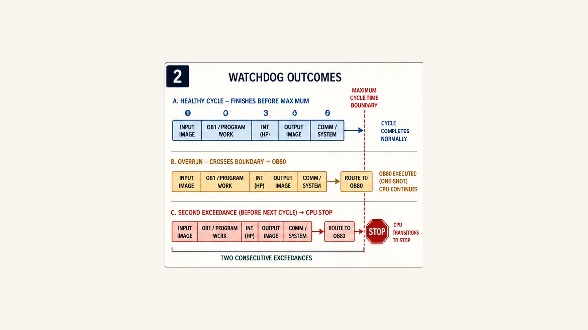
Design OB80 as a bounded first-out handler
Capture the first evidence before it is overwritten
Create the time-error OB supported by the exact CPU/project and inspect the start-information interface that TIA Portal generates. Optimized S7-1200/S7-1500 start information and legacy/migrated S7-300/400-compatible structures do not necessarily use the same member names or types. Map the actual generated values to a small capture interface; do not copy names from a screenshot.
At minimum, preserve:
- event ID/class and event number where provided;
- OB that was executing or implicated and its priority where provided;
- a monotonic occurrence counter with defined wrap;
- first-out latch and separate most-recent information;
- CPU/local time only when the clock is known and evidence handling is bounded;
- operating mode/state, recipe or batch identity and bounded data-size trigger;
- last approved program/hardware change identifier; and
- an HMI/SCADA diagnostic bit that does not itself create heavy communication work.
Do not format strings, search large arrays, write large data logs, transmit messages, reset the CPU or execute an unbounded recovery inside OB80. The handler is already running because timing capacity was lost. Its own work consumes time before the second-overrun boundary.
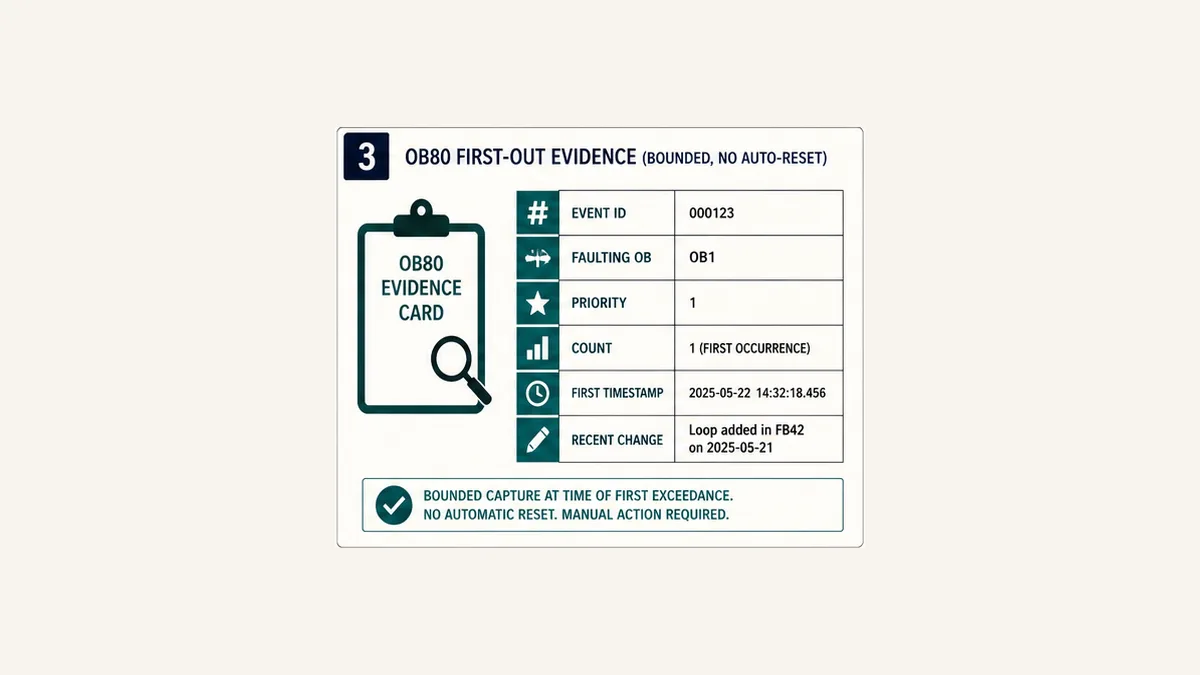
Executable SCL first-out helper
The following SCL helper is intentionally independent of the generated OB80 variable names. Create an instance DB, pass the exact OB80 start values through explicit conversions, and call it once per OB80 invocation with Capture := TRUE. Map EventId, FaultingOb and FaultingPriority only after inspecting the target's actual start information.
FUNCTION_BLOCK "FB_TimeErrorFirstOut"
VAR_INPUT
    Capture          : Bool;
    EventId          : Word;
    FaultingOb       : UInt;
    FaultingPriority : USInt;
END_VAR
VAR_OUTPUT
    Latched          : Bool;
    EventCount       : UDInt;
    FirstEventId     : Word;
    FirstFaultingOb  : UInt;
    FirstPriority    : USInt;
    LastEventId      : Word;
    LastFaultingOb   : UInt;
END_VAR
BEGIN
    IF #Capture THEN
        #EventCount := #EventCount + UDINT#1;
        #LastEventId := #EventId;
        #LastFaultingOb := #FaultingOb;

        IF NOT #Latched THEN
            #Latched := TRUE;
            #FirstEventId := #EventId;
            #FirstFaultingOb := #FaultingOb;
            #FirstPriority := #FaultingPriority;
        END_IF;
    END_IF;
END_FUNCTION_BLOCK
Run Structured Text in the simulator
There is deliberately no reset input in the OB80 helper. Clear first-out evidence through a separate authorized maintenance workflow after export and root-cause review. Configure retentivity only for the members and CPU behavior the incident record requires; then test STOP/RUN and power-cycle behavior. A retentive counter is not a substitute for the CPU diagnostics buffer.
Do not use RE_TRIGR as a universal repair
RE_TRIGR restarts the cycle monitoring time. Current Siemens help supports S7-1200, S7-1500 and S7-1200 G2 and documents a bounded overall execution relationship; the S7-1200 system manual describes extension up to ten times the configured maximum cycle time. That mechanism can be valid for a deliberately reviewed, finite operation, but it also delays detection of a late cycle.
Before using it, answer:
- Why is the operation allowed inside one cyclic program rather than chunked across cycles or placed in another architecture?
- What is the proven upper bound for every data size and branch?
- How does the extended cycle affect I/O/process response and every communication client?
- What happens if the instruction is skipped, reached late or called repeatedly?
- Does any standard-program change influence an F-runtime-group response calculation?
- Which test proves first exceedance, second exceedance, STOP and restart behavior?
If the only answer is “it stops nuisance faults,” do not deploy it.
Live mini-lab
Try it: press START, then STOP
A stop-dominant seal-in rung: START latches the motor output through its own contact, and STOP breaks the circuit.
Watch the output lamp: it stays on after START until you press STOP.
Free to start · runs in your browserOpens plcsimulationsoftware.com — same team
Measure whole cycle, OBs and suspect code separately
STEP 7 Online tools: overall cycle evidence
Connect through the approved engineering route and capture current, minimum and maximum cycle values from Online tools. On supported S7-1500 firmware, Siemens also exposes cycle statistics through the CPU display and Web server. Record when statistics last reset or RUN began, because a maximum without its observation window is ambiguous.
Measure representative operating states: idle, ordinary production, maximum recipe/product count, changeover, alarm storm, communication recovery, HMI/history load, trace active and approved online maintenance. Do not rely only on a short observation after restart.
RT_INFO: runtime statistics by OB and cycle
Current STEP 7 V21 documentation defines RT_INFO modes for specific-OB runtime statistics, higher-priority/communication percentages, shortest/longest/current user-program cycle time, configured settings and statistics reset. Exact MODE, OB, INFO type and CPU support belong to the current instruction help and selected target.
Use it to answer which OB consumes time and whether communication or higher-priority work changes the tail. Do not repeatedly reset statistics in production logic merely to keep the displayed maximum low. A reset should mark a controlled measurement window with operating state and project revision.
RUNTIME: bracket one block or code path
RUNTIME uses the same LREAL in/out memory on two calls and returns elapsed time in seconds on the second call. Siemens says it can include CPU processes occurring during the measured interval, such as higher-priority events or communication, and notes that optimized compilation can prevent exact statement-level interpretation.
// Static or DB-backed LREALs, not TEMP values whose lifecycle is unsuitable.
#IgnoredStart := RUNTIME(#RuntimeMemory);

"FC_SuspectWork"(
    ItemCount := #ItemCount,
    Result    => #WorkResult
);

#MeasuredSeconds := RUNTIME(#RuntimeMemory);

IF #MeasuredSeconds > LREAL#0.0 THEN
    #LastValidSeconds := #MeasuredSeconds;
    IF #MeasuredSeconds > #MaximumObservedSeconds THEN
        #MaximumObservedSeconds := #MeasuredSeconds;
    END_IF;
END_IF;
Run Structured Text in the simulator
On older S7-1200 firmware below the boundary cited in the instruction help, an internal counter overflow can produce nonpositive values periodically; Siemens says to ignore those runtime results. The exact current V21 target help must govern. Do not leave hundreds of measurement calls in the permanent hot path without measuring their effect.
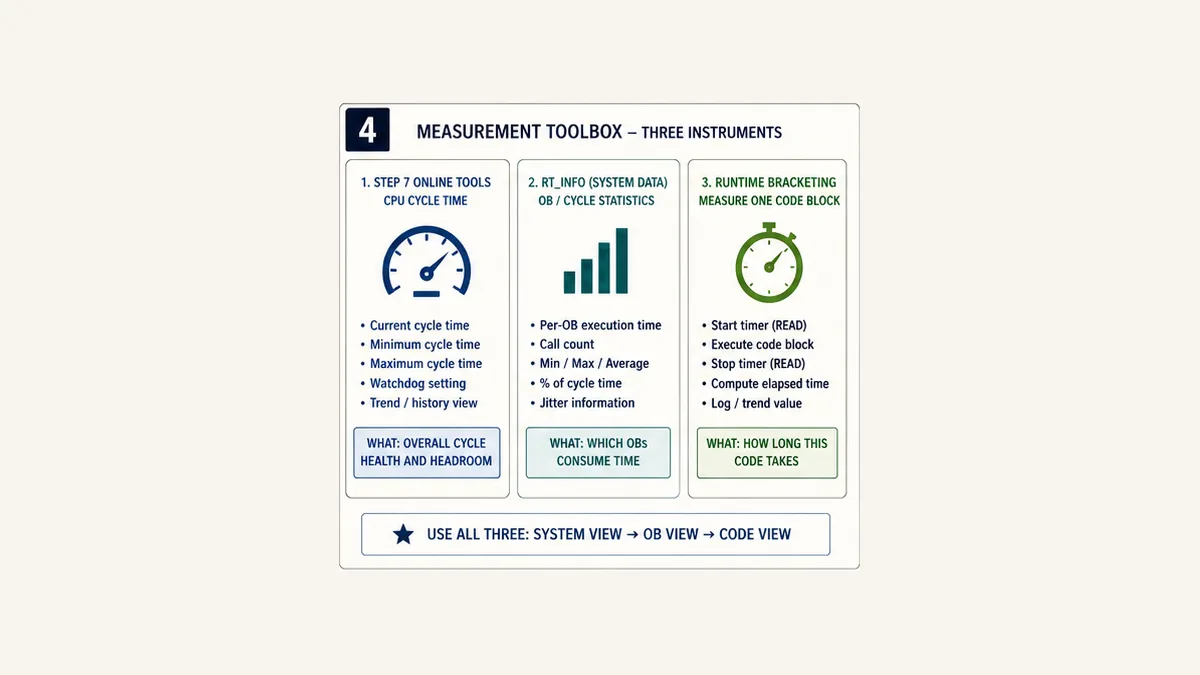
Worked fault: a data-dependent loop crosses the maximum
The nominal case hides the upper bound
Suppose a recipe-validation block scans an array of configured items in OB1. Commissioning used 10 items and the work consumed about 2 ms. A later recipe contains 500 items; validation now consumes 28 ms. With other cyclic work, interruption and system service, a 30 ms maximum-cycle setting is crossed.
The fault is not “FOR loops are forbidden.” The defect is that per-cycle work scales with data and its maximum was neither bounded nor tested. Simply raising the maximum to 60 ms permits the process to wait longer for every affected cyclic response. A better architecture processes a reviewed number of items per call, retains an index, publishes busy/done/error state and handles recipe changes deterministically.
| Cycle | ItemCount |
Start index | Items processed | End index | State | Cycle implication |
|---|---|---|---|---|---|---|
| 1 | 500 | 0 | 20 | 20 | busy | bounded validation slice |
| 2 | 500 | 20 | 20 | 40 | busy | cyclic control retains margin |
| 3–24 | 500 | previous | 20 each | 480 | busy | completion latency is explicit |
| 25 | 500 | 480 | 20 | 500 | done | one complete validated snapshot |
| recipe changes mid-run | new revision | any | 0 or approved restart policy | reset/snapshot | restarted | mixed-revision result is rejected |
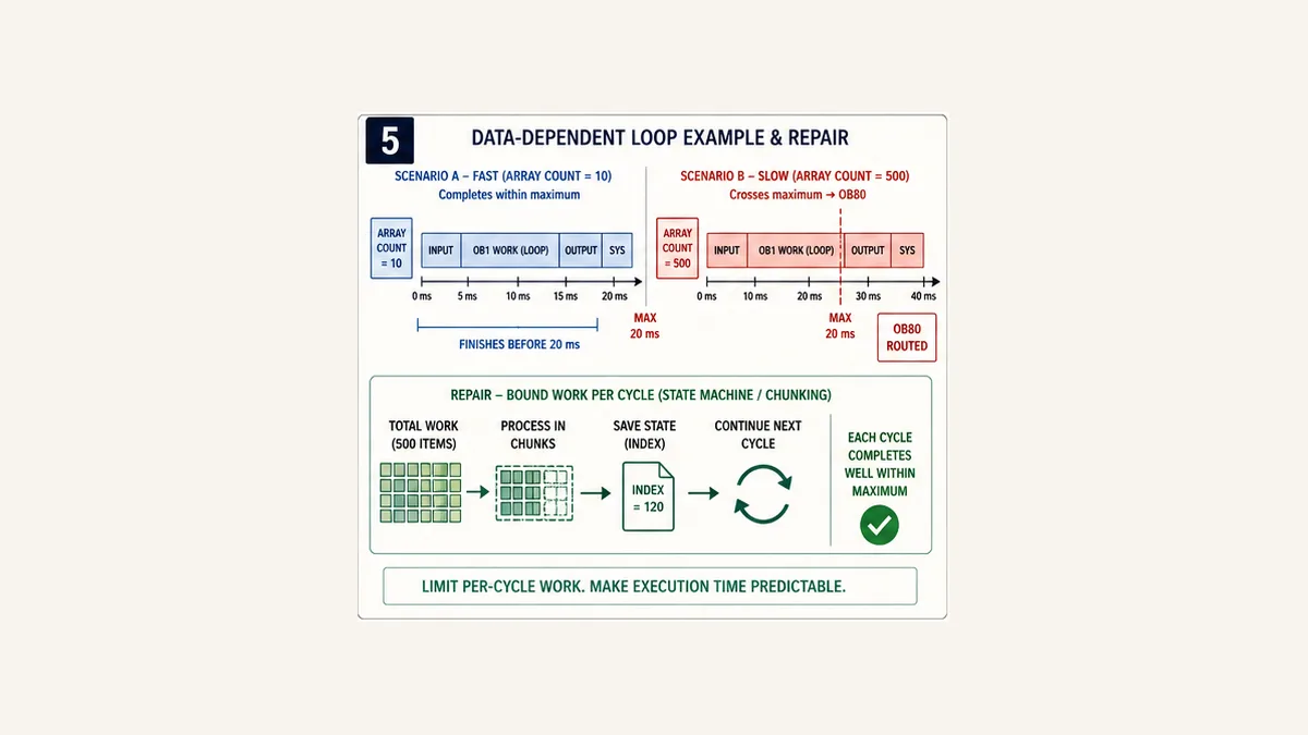
Executable bounded SCL worker
This teaching FB validates one fixed 500-element integer array in chunks. It does not control an output and does not use RE_TRIGR. The caller must create a stable snapshot or reject a changed Revision while processing; otherwise the result can combine two recipes.
FUNCTION_BLOCK "FB_BoundedArrayWorker"
VAR_INPUT
    Start           : Bool;
    Revision        : UDInt;
    ItemCount       : UInt;   // Accepted range: 0..500
    MaxItemsPerCall : UInt;   // Accepted range: 1..50
END_VAR
VAR_IN_OUT
    Items           : Array[0..499] of Int;
END_VAR
VAR_OUTPUT
    Busy            : Bool;
    Done            : Bool;
    Error           : Bool;
    InvalidIndex    : UInt;
END_VAR
VAR
    Index           : UInt;
    CapturedRev     : UDInt;
    Processed       : UInt;
END_VAR
BEGIN
    #Done := FALSE;

    IF #Start AND NOT #Busy THEN
        #Error := FALSE;
        #InvalidIndex := UINT#0;
        #Index := UINT#0;
        #CapturedRev := #Revision;
        #Busy := (#ItemCount > UINT#0) AND (#ItemCount <= UINT#500)
                 AND (#MaxItemsPerCall > UINT#0)
                 AND (#MaxItemsPerCall <= UINT#50);

        IF NOT #Busy THEN
            #Error := TRUE;
        END_IF;
    END_IF;

    IF #Busy THEN
        IF #Revision <> #CapturedRev THEN
            #Busy := FALSE;
            #Error := TRUE;
        ELSE
            #Processed := UINT#0;

            WHILE (#Processed < #MaxItemsPerCall)
                  AND (#Index < #ItemCount) DO
                IF (#Items[#Index] < INT#0)
                   OR (#Items[#Index] > INT#1000) THEN
                    #InvalidIndex := #Index;
                    #Busy := FALSE;
                    #Error := TRUE;
                ELSE
                    #Index := #Index + UINT#1;
                    #Processed := #Processed + UINT#1;
                END_IF;
            END_WHILE;

            IF #Busy AND (#Index >= #ItemCount) THEN
                #Busy := FALSE;
                #Done := TRUE;
            END_IF;
        END_IF;
    END_IF;
END_FUNCTION_BLOCK
Run Structured Text in the simulator
The WHILE remains bounded by MaxItemsPerCall <= 50, the array bound and the monotonically advancing index. Test zero count, 500 count, invalid limits, invalid first/last element, revision change, held Start, restart and repeated jobs. Tune MaxItemsPerCall from measured runtime and required total validation latency, not guesswork.
Diagnose a Siemens cycle-time fault step by step
1. Preserve the CPU's own evidence
Before STOP/RUN, download, reset or factory reset, export or capture the diagnostics buffer and Online & Diagnostics state according to the approved procedure. Siemens says the buffer contains ordered CPU/module diagnostic events with timestamp, error ID and event-specific information and is retained through power loss until factory reset. Capture time synchronization status because a precise-looking timestamp can still be wrong.
Record whether OB80 existed and which start event occurred. A maximum-cycle exceedance, interrupted time-event overlap and queue/warning-limit event require different hypotheses.
2. Establish the measured timing window
Capture current/minimum/maximum cycle time, maximum-cycle property, CPU utilization/runtime shares, relevant OB runtimes and the operating state. Note when statistics reset. Compare normal production with the exact fault mode—large recipe, communication recovery, diagnostics open, trace active or online change.
3. Narrow from OB to code and data
Use RT_INFO or supported online statistics to identify the OB whose execution count or runtime changed. Use RUNTIME sparingly around the suspected call. Compare data size, loop bounds, state-machine path, indirect/indexed access, string parsing, communication calls and recently enabled diagnostics. Look for a finite but unexpectedly large path as well as a literal endless loop.
4. Separate code growth from preemption and system load
A lower-priority program-cycle OB can appear late because higher-priority cyclic/hardware interrupts execute, because the cyclic call path grew, or both. Communication and system activity can alter measured elapsed time. Put the OB timeline beside the code measurement. A block runtime that remains stable while total cycle grows points away from that block.
5. Reproduce and repair in an isolated setup
Recreate the triggering data and workload on an approved test CPU or high-fidelity target environment. An editor simulation that does not implement target scheduling and system services cannot prove the watchdog. Repair the root cause: bound loops, reject invalid count, chunk work, reduce repeated conversions/copies, restructure scheduling, correct interrupt frequency, reduce unnecessary communication/diagnostic load or select adequate controller capacity.
6. Prove normal, worst-case and recovery behavior
Repeat startup, minimum/maximum datasets, peak I/O/communication, alarm storm, online observation, diagnostics and permitted maintenance. Trigger the reviewed time-error test only through an approved safe method. Validate OB80 evidence, first/second overrun behavior on the exact test target, CPU state, output/device state, operator indication and deliberate restart.
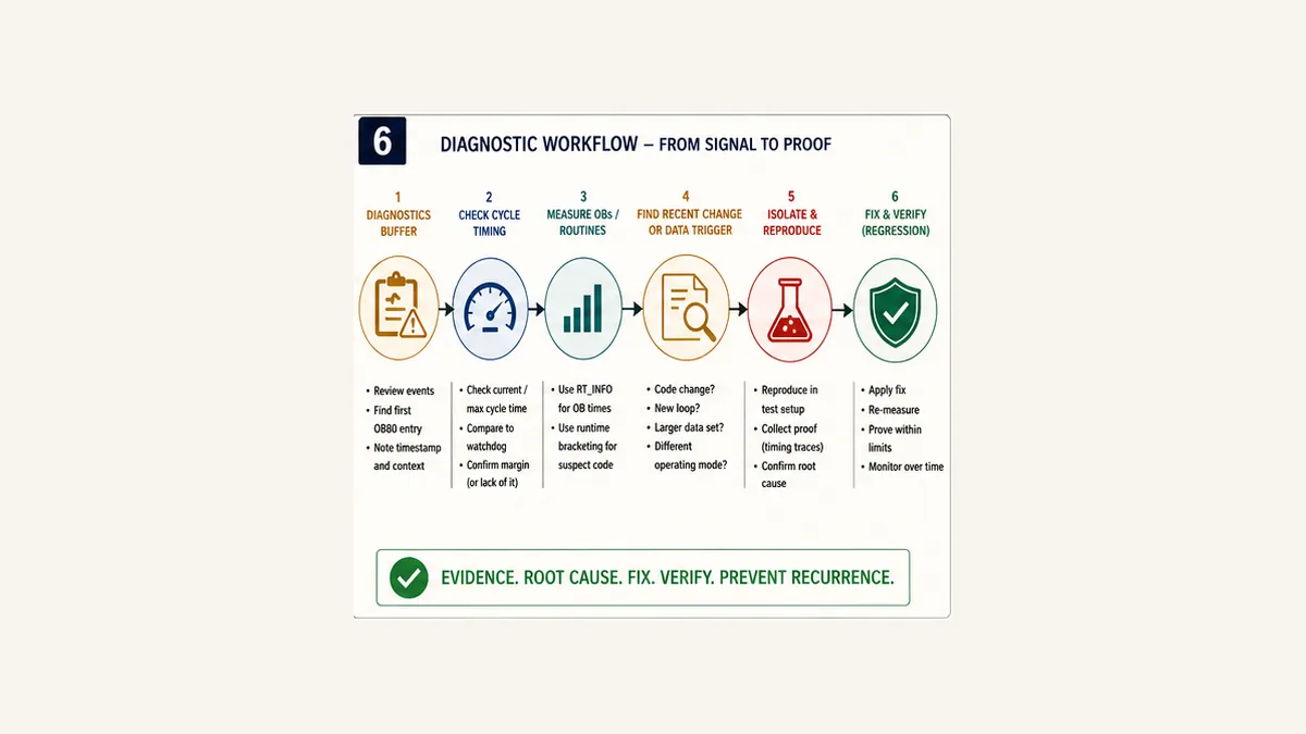
Symptom-to-cause matrix
| Symptom | Best first evidence | Likely hypotheses after proof | Weak response to avoid |
|---|---|---|---|
| CPU enters STOP with time error | diagnostics buffer, OB80 presence and event | first overrun without handler, second same-cycle overrun, another time-error event | restart before capture |
| OB80 count rises but CPU stays RUN | event/start info and cycle maximum | intermittent long path, interrupt overlap, queue limit | treating RUN as healthy |
| fault only on largest recipe | item count and bracketed block runtime | data-dependent loop/copy/string work | increasing threshold without bounding data |
| fault after faster cyclic interrupt | priority, period, runtime and overlap | higher-priority preemption or request backlog | optimizing OB1 only |
| fault while online diagnostics/trace active | same test with approved observation loads | measurement/communication overhead exposes low margin | assuming tools can never affect timing |
| maximum rises but suspect block is stable | RT_INFO OB/runtime shares | another OB, communication or system activity | rewriting the stable block |
| HMI freezes but cycle statistics are normal | HMI tag quality and update age | communication/session/polling problem | changing CPU cycle watchdog |
| motor fails to start but cycle is normal | command, feedback and process timeout | equipment/permissive/field fault | adding OB80 logic |
| CPU returns RUN but equipment state is wrong | startup/retention/output/device evidence | restart sequencing or stale request | treating RUN as process readiness |
Choose a defensible maximum cycle time
Start with the required sensor-to-action response, not a multiple of average scan. Budget input acquisition/update, scheduling phase, maximum cyclic execution, output update, network/device execution, actuator response and feedback. Include safety functions only through their certified reaction-time method—not this standard-program calculation.
For a teaching example, suppose an ordinary control response budget is 80 ms:
| Component | Witnessed worst-case teaching value |
|---|---|
| input update/filter and phase | 12 ms |
| cyclic start wait | 15 ms |
| user/system cycle execution | 25 ms |
| output/network application | 10 ms |
| actuator/feedback recognition | 12 ms |
| engineering reserve | 6 ms |
| total | 80 ms |
This table does not say “set the watchdog to 25 ms.” The CPU maximum must account for Siemens' exact cycle definition, observed tail, startup/maintenance modes and the desired reaction before the process budget is consumed. If the valid worst-case cycle is already near the process limit, the repair may require architecture or controller capacity rather than a new number.
Use three evidence sets:
- requirement: maximum allowed process and cyclic response by operating mode;
- measurement: representative maximum distribution, not only mean/current; and
- reaction: exact OB80/STOP and output/device consequences on the target.
Approve the threshold only when all three agree. Record the old/new value, cause, data/load matrix, margin and sign-off.
Sixteen acceptance tests
| ID | Test | Expected evidence |
|---|---|---|
| SW-01 | verify CPU, firmware, TIA version and standard/F/R/H classification | complete manifest and governing documents |
| SW-02 | capture maximum-cycle property and OB architecture | as-found screenshot/export plus revision |
| SW-03 | establish idle timing distribution | current/min/max and observation window |
| SW-04 | establish maximum valid process/load distribution | recorded states, datasets, clients and timing tail |
| SW-05 | compare RT_INFO OB statistics | execution owner and call count identified |
| SW-06 | bracket suspect code with RUNTIME | valid seconds and repeated data/load results |
| SW-07 | exercise zero/minimum/maximum data | all loops and copies remain bounded |
| SW-08 | inject invalid count/index/revision | code rejects or restarts deterministically |
| SW-09 | verify chunked worker completion | per-cycle bound and total completion latency pass |
| SW-10 | trigger reviewed first time-error case on safe target | diagnostics entry and OB80 first-out match expectation |
| SW-11 | verify absent/present OB80 behavior as authorized | exact CPU state/reaction captured, not assumed |
| SW-12 | verify second-overrun behavior only where safely approved | STOP/escalation and evidence match exact documentation |
| SW-13 | test STOP/RUN and power-cycle evidence retention | first-out, counter and diagnostics follow design |
| SW-14 | validate CPU/module/network/output field state | every layer reaches its specified fault state |
| SW-15 | test operator/maintenance recovery | no stale command, surprise restart or evidence loss |
| SW-16 | repeat peak-load regression after repair | requirement, timing margin and reaction all accepted |
Use the PLC troubleshooting simulator to practise scan-order reasoning, data-dependent paths, first-out evidence and controlled fault isolation. It does not compile a TIA Portal project or emulate an S7 CPU, OB scheduler, process image, OB80, RT_INFO, RUNTIME, CPU STOP/output behavior, firmware, Profinet devices, F-runtime group or safety response. Repeat the Siemens-specific matrix on the approved target. Evaluate click, scenario start, registration and paid conversion together before changing this CTA.
Siemens watchdog answer map
- What is the watchdog timer in a Siemens PLC? For ordinary S7 cyclic execution, it is maximum cycle time/cycle monitoring enforced by the CPU operating system; it is not a
TON. - Where is the S7-1500 watchdog setting? It is a CPU cycle property in the compatible STEP 7 project. Menu placement varies by version; record the exact project value rather than navigating from an old screenshot.
- What happens when S7-1500 maximum cycle time is exceeded? The CPU records a time error and attempts OB80; without the handler it can STOP, and a second exceedance within the cycle can STOP even with OB80.
- What is Siemens OB80? The time-error organization block invoked for supported time-error events such as a first maximum-cycle exceedance and certain interrupt/queue conditions.
- Can OB80 keep a Siemens PLC running? It can handle the first documented time error when present, but a second same-cycle exceedance can force STOP. Keep the handler bounded and validate process response.
- What does RE_TRIGR do? It restarts cycle monitoring. It changes the effective supervised interval and should be used only for a proven bounded purpose.
- How do I read Siemens PLC cycle time? Use STEP 7 Online tools and supported CPU display/Web server views; use
RT_INFOfor program/OB statistics. - How do I measure one SCL block's runtime? Call
RUNTIMEbefore and after the block with the sameLREALmemory and evaluate the valid second result. - Why does a Siemens watchdog trip only on large recipes? A loop, copy, sort, string or indirect data path may scale with item count and cross the boundary only at the largest valid dataset.
- Should I increase the S7 maximum cycle time? Only after identifying the cause and proving the new detection/reaction time still meets the process and safety-related constraints.
Frequently asked questions
What is a watchdog timer in a Siemens PLC?
For ordinary S7-1200/S7-1500 program-cycle supervision, the CPU operating system monitors cyclic execution against a configured maximum cycle time. Crossing it generates a time error and can invoke OB80 or put the CPU into STOP according to the exact target and event. Other Siemens watchdogs—F-runtime, communication and device monitoring—are different layers.
Is the Siemens PLC watchdog a TON timer?
No. TON is application code and depends on its OB continuing to execute. CPU cycle monitoring can detect that cyclic execution itself exceeded a boundary. Use TON for process contracts such as missing motor feedback, not as the sole supervisor of the task that calls it.
What is maximum cycle time in an S7-1500?
It is a configurable upper limit for cyclic-program runtime under Siemens' documented cycle definition, including relevant nested higher-priority execution. Current V21 documentation gives 150 ms as the default and 1–6000 ms as the configurable range for non-redundant S7-1500 CPUs; other CPU classes require their own documentation.
What happens if the maximum cycle time is exceeded?
The CPU creates a diagnostic time-error event and attempts to start OB80. Without the applicable OB80, it can enter STOP. With OB80, the first event can be handled while RUN continues; a second maximum-cycle exceedance in the same cycle can still put the CPU into STOP. Verify the exact CPU/firmware and event.
What is OB80 in Siemens TIA Portal?
OB80 is the time-error organization block. It can be invoked for a maximum-cycle exceedance and other documented timing events such as interrupt overlap or queue/warning-limit conditions. Its generated start information identifies the event; interfaces differ between current optimized and legacy-compatible structures.
What should I program inside OB80?
Keep it short and deterministic: latch first-out event identity, faulting OB/priority where provided, a counter and a small diagnostic state; command only the reviewed response. Avoid array searches, heavy strings, large logs, communications or automatic reset. Export and clear evidence later through an authorized maintenance workflow.
What does RE_TRIGR do in a Siemens PLC?
RE_TRIGR restarts cycle monitoring time. It can support a deliberately bounded operation, but it delays watchdog detection and changes response timing. Prove the upper bound, process effect, call behavior and target-specific limit. It is not a general fix for long scans.
How can I read cycle time in TIA Portal?
Use the CPU's STEP 7 Online tools cycle statistics and record current, minimum, maximum and the measurement window. Supported S7-1500 versions can also expose statistics through the display/Web server. RT_INFO can obtain cycle and OB runtime data from the program where supported.
What is the difference between RT_INFO and RUNTIME?
RT_INFO returns selected CPU runtime statistics such as OB or cycle data according to its mode. RUNTIME measures elapsed time between two calls using the same memory and is useful for one block/path. Neither replaces the diagnostics buffer or a representative operating-state test.
Why does my Siemens PLC watchdog trip intermittently?
Rare data-dependent paths, higher-priority interrupts, queue/overlap events, communication or diagnostic load, online changes, recipe size and hardware/runtime conditions can create a long tail. Preserve the event, correlate cycle and OB statistics, bracket suspect code and reproduce the exact data/load rather than tuning from average time.
Can increasing maximum cycle time fix an OB80 fault?
It can prevent the same observed execution from crossing the threshold, but that is not proof of a repair. A higher value delays time-error reaction and may violate required response. Identify why time grew, bound it, measure worst-case margin and validate output/recovery behavior before approving any setting change.
Does CPU STOP always turn every output off?
Do not assume so. CPU, I/O module, network device, drive, retained application state and configured substitute/fault behavior all contribute. Validate every actual output and process state on the exact architecture under an approved fault test.
Is an S7 standard cycle watchdog the same as an F-runtime watchdog?
No. Siemens Safety uses F-runtime-group monitoring and response-time calculations protected by the safety project and signatures. Standard maximum cycle time and OB80 guidance cannot be copied into the F-runtime design. Follow the certified Safety documentation and validation lifecycle.
Can a simulator prove Siemens watchdog behavior?
A logic simulator can expose unbounded loops, state errors, scan-order mistakes and weak recovery logic. It cannot prove target scheduling, maximum-cycle enforcement, OB80 start information, CPU STOP, process-image timing, physical I/O/device reactions, firmware, redundancy or safety response. Use an approved representative Siemens target for those tests.
Sources, review scope and limitations
This guide was last reviewed on 31 August 2026. It is an engineering pattern, not a TIA Portal project, universal watchdog preset, safety calculation or authorization to force a controller into a timing fault. Exact manuals, risk assessment, change control, backups and site procedures govern the installation.
Primary sources reviewed:
- Siemens STEP 7 V21: Cyclic OBs for S7-1500 — cycle contribution, process image, maximum-cycle event and OB80 start IDs.
- Siemens S7-1500/ET 200MP V21: Different cycle times — current standard maximum defaults/range, OB80 outcome and cycle statistics.
- Siemens STEP 7 V20: Cycle time and maximum cycle time — operating-system cycle supervision, minimum cycle and second-overrun boundary.
- Siemens STEP 7 V21: RE_TRIGR — current restart-cycle-monitoring instruction scope.
- Siemens STEP 7 V21: RT_INFO — OB, communication, user-program and cycle statistics modes and measurement lifecycle.
- Siemens STEP 7 V20: RUNTIME — elapsed runtime measurement, units, interruptions and older S7-1200 counter-overflow limitation.
- Siemens S7-1200 System Manual V4.6 — S7-1200 program execution, time-error OB, diagnostics and second-exceedance behavior.
- Siemens STEP 7 V21: Basic information on the diagnostics buffer — retained ordered event, timestamp and error-ID evidence.
- Siemens S7-1500/ET 200MP V21: Web-server diagnostics buffer — authorized web view and load-strategy boundary.
- Siemens STEP 7 V21 Safety: defining an F-runtime group — separate F-OB scheduling, group monitoring and response-time requirements.
- Siemens STEP 7 V21 Safety: F-runtime communication monitoring — safety-related monitoring-time calculation boundary.
- OSHA 29 CFR 1910.147: Control of hazardous energy — United States hazardous-energy-control requirements; other jurisdictions and site rules may differ.
The six figures are original conceptual illustrations made for this page. Dates, IDs and timing values inside them are teaching examples, not captured plant evidence. They do not reproduce TIA Portal screens, certify a CPU, define safe output state or replace target testing.
Now run it · free to start
Learn a repeatable way to find the fault
Split a stopped machine into input, logic, output and physical response, and take the measurement that proves each stage. Practised on simulated machines. Free to start.
Ownership disclosure: PLC Programming IO and PLC Simulation Software are operated by the same publisher.
PLC Programming IO Editorial Team
Industrial automation education, references, and software testing
The PLC Programming IO Editorial Team publishes sourced industrial-automation education and documents how material is reviewed, tested, and corrected. A team byline means the publisher is responsible for the page; it does not represent a fictional person or imply an engineering licence.
Coverage:
- • PLC programming concepts and examples
- • Vendor software tutorials and comparisons
- • SCADA, HMI, protocols, and instrumentation
- • Training, careers, and reference material
Review standard:
- • Prefer primary and official sources
- • Record software versions when material
- • Separate tested facts from estimates
- • Publish material corrections
Important scope note
This site provides education, not project-specific engineering approval. Safety, code, and compliance decisions require a qualified person with access to the actual machine and jurisdiction.